ICP DAS USA ET-2255U Quick Start Manual
Hide thumbs
Also See for ET-2255U:
- User manual (125 pages) ,
- Quick start manual (9 pages) ,
- Quick start manual (8 pages)
Advertisement
Quick Links
What's in the box?
The package includes the following items:
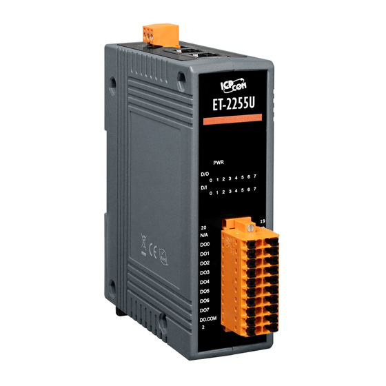
ET-2255U Module x 1
Related Information
ET-2200 Series Product Page:
Documentation & Firmware:
NS-205/MDR-20-24 Product Page (optional):
Technical support:
ET-2255U Quick Start
service@icpdas.com
v1.2, Jun. 2018
Quick Start x1
(This Document)
P1
Advertisement

Related Manuals for ICP DAS USA ET-2255U


Summary of Contents for ICP DAS USA ET-2255U
- Page 1 ET-2255U Quick Start v1.2, Jun. 2018 What’s in the box? The package includes the following items: ET-2255U Module x 1 Quick Start x1 (This Document) Related Information ET-2200 Series Product Page: Documentation & Firmware: NS-205/MDR-20-24 Product Page (optional): Technical support: service@icpdas.com...
- Page 2 Disable or well configure your Windows firewall and Anti-Virus firewall first, else the “Search Servers” on Chapter 5 may not work. (Please contact with your system Administrator) Connect both the ET-2255U and your PC to the same sub network or the same Ethernet switch. Supply power (+10~+30 V ) to the ET-2255U.
- Page 3 Pin Assignments & Wiring Note Pin Assignments: Wire Connections: Digital Input/ Digital Readback as 0 Readback as 1 Readback as 1 Readback as 0 Counter Output OFF State ON State Close to GND Open +S5 V +S5 V Load Load Sink...
- Page 4 Wiring the DI and DO for Self-test A tip for connecting the wire to the connector A tip for removing the wire from the connector 1) Connect the DI0 pin (Pin17) to the DO0 pin (Pin18). 2) Connect the External Power +24V to the DI.COM pin (Pin01). 3) Connect the External Power GND to the DO.COM (Pin02).
-
Page 5: Modbus Address
Modbus Address (0xxxx) DO address: Bits Begin Access Points Description Range address Type Point 0 (0x0) Digital Output Channels 0: OFF, 1: ON Clears the status of all high 32 (0x20) 1: Clear latched DI channels Clears the status of all low 33 (0x21) 1: Clear latched DI channels... -
Page 6: Configuring Network Settings
Configuring Network Settings 1) Run the eSearch Utility. The eSearch Utility is located at: http://ftp.icpdas.com/pub/cd/6000cd/napdos/software/esearch/ 2) Click the “Search Servers” to search your ET-2255U. 3) Double-click your ET-2255U to configure the settings Factory Default Settings of ET-2255U: IP Address 192.168.255.1... - Page 7 ET-2255U is working well with new configuration. 2) Click the name of ET-2255U to select it. 3) Click the “Web” button to log in to the web configuration pages. (Or enter the URL address of the ET-2255U in the address bar of the browser.) ...
- Page 8 5) In the “Home” page allows a simple test to be performed to verify the Digital Input and Output functionality. 6) In the “Digital I/O” section, click the “DO0” button to ON (Red). 7) The corresponding DI becomes green for DI0 is ON. ...
Need help?
Do you have a question about the ET-2255U and is the answer not in the manual?
Questions and answers