Table of Contents
Advertisement
Installation, Operation, and Maintenance
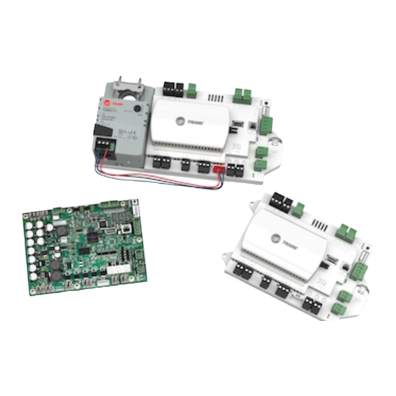
Symbio® 210 Programmable
Variable-Air-Volume (VAV) Box
Controller
Only qualified personnel should install and service the equipment. The installation, starting up, and servicing of heating, ventilating, and air-
conditioning equipment can be hazardous and requires specific knowledge and training. Improperly installed, adjusted or altered equipment
by an unqualified person could result in death or serious injury. When working on the equipment, observe all precautions in the literature and
on the tags, stickers, and labels that are attached to the equipment.
June 2021
SAFETY WARNING
BAS-SVX084A-EN
Advertisement
Table of Contents
Troubleshooting

Related Manuals for Trane Symbio 210


Summary of Contents for Trane Symbio 210
- Page 1 Installation, Operation, and Maintenance Symbio® 210 Programmable Variable-Air-Volume (VAV) Box Controller SAFETY WARNING Only qualified personnel should install and service the equipment. The installation, starting up, and servicing of heating, ventilating, and air- conditioning equipment can be hazardous and requires specific knowledge and training. Improperly installed, adjusted or altered equipment by an unqualified person could result in death or serious injury.
- Page 2 OSHA, NFPA 70E, or other country-specific requirements for arc flash protection, PRIOR to servicing the unit. NEVER PERFORM ANY SWITCHING, DISCONNECTING, OR VOLTAGE TESTING WITHOUT PROPER ELECTRICAL PPE AND ARC FLASH CLOTHING. ENSURE ELECTRICAL METERS AND EQUIPMENT ARE PROPERLY RATED FOR INTENDED VOLTAGE. ©2021 Trane BAS-SVX084A-EN...
- Page 3 Non-Trane personnel should always follow local regulations. Copyright This document and the information in it are the property of Trane, and may not be used or reproduced in whole or in part without written permission. Trane reserves the right to revise this publication at any time, and to make changes to its content without obligation to notify any person of such revision or change.
-
Page 4: Table Of Contents
Transformer Recommendations ....... . 12 Symbio 210 Controller Power Wiring ......13 Wiring Requirements . - Page 5 Troubleshooting Procedures ........55 Symbio 210 Controller Failure ........55 Symbio 210 Controller Communication Loss .
-
Page 6: Overview
• Ventilation Flow Control (VFC) When the Symbio 210 controller is configured for VFC, it can be applied to a VAV terminal and tempers cold outdoor air that is brought into a building for ventilation purposes. The tempered air is intended to supply an air handler unit (AHU), which provides comfort control to the zones it is serving. -
Page 7: Controller Specifications And Dimensions
• CAN ICES-003(B)/NMB-003(B) • Communications BACnet MS/TP, BACnet IP, or BACnet Zigbee (Air-Fi). • The Symbio 210 is BACnet Testing Laboratory (BTL) certified to revision 15 of the ASHRAE BACnet-135 standard as a Building Controller (BC) profile device. • The European Union (EU) Declaration of Conformity is available from your local Trane® office. - Page 8 Overview Figure 2. Dimensions (without actuator) Figure 3. Dimensions (Trane VAV factory version) Note: Symbio 210e is the same dimensions at Symbio 210. BAS-SVX084A-EN...
-
Page 9: Shipping And Storage
Tracer SC+ or a 3rd party building automation system that supports BACnet. The Symbio 210 controller is designed with the ability to be applied in flow tracking applications. This allows the controller to be paired Flow Tracking: with one of its peers to mirror the flow of the lead unit, with or without an offset (positive or negative static pressure as desired). -
Page 10: Device Connections
Solid state open collector Minimum dwell time is 25 ms On and 25 ms Off. controller provides the 24 Vac that is Symbio 210 Binary input (BI1) 24 Vac detect/dry contact required to drive the binary inputs when using the recommended connections. -
Page 11: Device Inputs/Outputs
24 Vac, Class II power Table 4 provides details for each type input/output. Table 4. Symbio 210 inputs and outputs Universal Inputs UI1 and UI2 Analog Inputs 1 through 3 Note: Configuration options when used as spare; 4–20mA, 0-10V, Note: Configuration options when used as spare;... -
Page 12: Wiring Installation
The acceptable voltage is 20.4 to 27.6 (24 Vac nominal). However, voltages at either extreme may result in increased system instability. • Verify that the zone sensor connections are correct as detailed in the Symbio 210 controller wiring section. •... -
Page 13: Symbio 210 Controller Power Wiring
2. Remove the lockout/tagout from the line voltage power to the electrical cabinet. 3. Energize the transformer to apply power to the Symbio 210 controller. 4. Observe the cleared Symbio 210 controller when power is applied to verify the power check sequence as follows: a. -
Page 14: Guidelines
Use U.L. listed, Class 2 power transformer, 20.4 to 27.6 Vac (24 Vac nominal). • Size the transformer to provide adequate power to the Symbio 210 controller (24 VA maximum) and outputs (maximum 12 VA for each binary output). Important: A dedicated 24 Vac, Class 2 transformer is recommended to power the Symbio 210 controller. - Page 15 • 0.1 VA • Binary Out for Air Damper (only one energized at a time, not • 0.1 VA including actuator draw) • Trane F Series Air Damper Actuator (Taken from Table 7, p. • 4.0 VA Total 12.5 VA...
-
Page 16: Bacnet Ms/Tp Communication Link
• “Wiring Guidelines” • “Wiring Best Practices,” p. 17 • “Setting Up the Symbio 210 Controller on a BACnet MS/TP Link,” p. 18 • “Setting the Address,” p. 18 • “BACnet Networks Without a Tracer SC+ System Controller,” p. 22 •... -
Page 17: Wiring Best Practices
In open plenums, avoid running wire near lighting ballasts, especially those using 277 Vac. • Use same communication wire type, without terminators, for the zone sensor communication stubs from the Symbio 210 controller IMC terminals to the zone sensor communication module. • Zone Sensor communication wiring length limits of 300 ft. (100 m). -
Page 18: Setting Up The Symbio 210 Controller On A Bacnet Ms/Tp Link
Connect the BACnet link to the Symbio 210 controller terminals labeled Link on the lower-right corner of the Symbio 210. Incoming wires can be connected to the first two terminals, and the outgoing wires can be connected to the second set of terminals, so there is only one wire per termination. -
Page 19: Bacnet/Ip Communication Link
Wiring Installation BACnet/IP Communication Link This subsection provides information on the following: • Wiring Guidelines • Wiring Best Practices • Setting up the Symbio 210e Controller on a daisy chain BACnet/IP Link • Setting up the Symbio 210e Controller on a home run BACnet/IP Link •... -
Page 20: Connecting The Wires
Wiring Installation Figure 6. BACnet/IP daisy chain wiring for Symbio 210e IM C IM C + 24 LINK 1 LINK 2 LINK 3 LINK 1 LINK 2 LINK 3 IM C STATUS Tracer LINK ® SERVICE TOOL ADDRESS x100 XFMR + 24 Figure 7. -
Page 21: Wiring Best Practices
Zone sensor communication wiring length limit of 328 feet (100 meters). Setting the Symbio 210 Controller on a Daisy Chain BACnet/IP Link Observe the following when setting up the Symbio 210 controller on a daisy chain BACnet/IP link: • Use CAT5 or CAT5e non-shielded twisted pair, Ethernet cable with RJ45 connectors for BACnet/ IP installations. -
Page 22: Bacnet Networks Without A Tracer Sc+ System Controller
It can be the same number as the MAC Address, determined by the rotary address dials on the Symbio 210 controller. For example, if the rotary address dials are set to 042, both the MAC Address and the BACnet Device ID are 042, OR •... -
Page 23: Device Id Assignment For Bacnet/Ip Devices
Zone Sensor Hard Wired Option Depending on the zone sensor options used, a maximum of seven (7) wires may be required to run from the Symbio 210 controller to the zone sensor. The zone sensor options are: • Zone sensor (temperature only); Part Number X1351152801. - Page 24 The wire that runs from a zone sensor to a unit controller is commonly referred to as the communication stub. It is the wire that goes from the IMC terminal link on the Symbio 210 controller down to the zone sensor. At least one zone sensor per area or controller network should include the optional communications module.
-
Page 25: Duct Temperature Sensor Wiring
“Zone Sensor Mounting and Wiring,” p. Duct Temperature Sensor Wiring The Symbio 210 controller has one analog input for a discharge air sensor, which can be user- configured for supply air temperature. The typical mounting position of the supply air sensor is... -
Page 26: Binary Wiring
Binary Wiring Binary Input Wiring Each Symbio 210 controller provides one (1) binary input (BI1), which is configured for occupancy with the standard VAV code. The binary input can be configured with the Tracer TU service tool for occupancy or other use. The input associates 0 Vac with open contacts and 24 Vac with closed contacts. -
Page 27: Controller Leds
Controller LEDs This section describes how to verify and interpret the Symbio 210 controller LEDs and safely operate the controller. LEDs are used to provide controller serviceability. The Symbio 210 controller has the following LEDs located on the front (refer to Figure Table 9, p. - Page 28 • Not lit: cycle the power to reestablish communication. In addition, check polarity and baud rate. Shows solid green when When the Symbio 210 is placed into the LED has been boot mode, the system will not run pressed. any applications such as trending, scheduling, and TGP2 runtime.
- Page 29 Indicates a corresponding binary output has been If you are currently powering the commanded ON. Symbio 210 from a USB port, the Led lights will turn ON. However, Shows solid yellow. • Relay coil: indicates that a command has been made to the binary outputs will not be energize.
- Page 30 Controller LEDs Each of the following codes is a two digit number following this pattern: First digit, 600mS pause, Second digit, 2 second pause and then repeat the pattern. Table 10. Marquee LED status and error codes LED Blink Pattern Message Description Action by User...
- Page 31 Controller LEDs Table 10. Marquee LED status and error codes LED Blink Pattern Message Description Action by User Thumb drive with .scfx file, power down, set address Attempted load of the field kernel or device Load Field Fail rotaries to 991, and power up. tree failed.
-
Page 32: Symbio 210 Controller Points And Parameters
Symbio 210 Controller Points and Parameters You can use the Tracer TU service tool to view or adjust points and parameters in the Symbio 210 controller. It is a software application for monitoring, configuring, balancing, and testing Trane unit controllers, such as the Symbio 210 controller. -
Page 33: Analog, Binary, And Multistate Screens
Ventilation Setpoint: Arbitrated final value of the zone ventilation requirement. • Air Flow Stpt Active Min: Displays active minimum flow setpoint. Note: The Symbio 210 may not be using the minimum flow setpoint if space conditions require more airflow). •... -
Page 34: Controller Status Screen
Controller Status Screen Program The Symbio 210 controller has up to three (3) TGP2 programs downloaded and defined in the factory as part of the factory commissioning process. The three programs are a base program for damper control, fan, and reheat control. When looking at programming section of Controller Status tab, operation of these programs can be monitored. -
Page 35: Setup Parameters Screen
Typically, it is not necessary to change this value. For Trane units, the nominal airflow and unit flow gain are based on unit size and are not adjustable. The default unit flow gain for generic VAV boxes is 1.0. - Page 36 Symbio 210 Controller Points and Parameters Flow Setpoints Setup • Airflow Setpoint Minimum: Although the UCM will read flow down to 5% of cataloged, the range of MIN FLOW settings is 0% or 10% to 100% of cataloged. The UCM will not drive its flow below this minimum flow value under normal operating conditions while in the cool mode.
-
Page 37: Commissioning Screen
Calibrate Air Valve (Start Button): Displays the Calibrate Air Valve dialog box. Use this air balancing tool to perform a basic two-point air balance for the Symbio 210 controller. See the Tracer TU Help for Programmable Controllers (“Configuring and Commissioning Equipment”... -
Page 38: Configuration Screen
Profile: This allows for selection between three operational programs. The three programs are Space Temperature, Ventilation Flow, and Flow Tracking. • Box Size: Used to select a Trane F-style box size or Generic Box. • Air Damper Opens: Chose between Clockwise and Counter-Clockwise damper rotation to open the damper. - Page 39 Number of Reheat Stages (PWM or Staged): Choose the correct number of reheat stages (1-3) Sensor Options If a Symbio 210 has a wireless zone sensor and is a member of Tracer SC wireless link, you can install this feature to configure the unit controller so it will communicate the wireless zone sensor battery level to the Tracer SC once it is installed on the Tracer SC.
-
Page 40: Calibration, Operation Modes, And Control
Enabled Enabled Electric or On/Off hot Disabled Enabled water Occupancy Modes The Symbio 210 controller has four (4) valid occupancy modes: • Occupied mode • Unoccupied mode • Occupied standby mode • Occupied bypass mode Occupied Mode Occupied mode is the normal (default) operating mode for occupied spaces or daytime operation. -
Page 41: Unoccupied Mode
Calibration, Operation Modes, and Control Unoccupied Mode Unoccupied mode, known as night setback, is the normal operating mode for unoccupied spaces or nighttime operation. Unoccupied setpoints enable or disable occupied space temperature control. When the controller is in the unoccupied mode, and configured for space temperature control, the controller attempts to keep the space temperature between the active unoccupied heating setpoint and the active unoccupied cooling setpoint. -
Page 42: Space Temperature Control (Stc) For Single Duct And Fan-Powered Units
Calibration, Operation Modes, and Control Space Temperature Control (STC) for Single Duct and Fan-powered Units Single Duct Units Space Temperature Control Mode Space temperature control is one of three supported control algorithms (the other two supported control algorithms are “Ventilation Flow Control (VFC),” p. 50 “Flow Tracking (FTC),”... - Page 43 Heating operation and Reheat are two different entities. Auto-changeover The auto-changeover feature is used if the RTU has heat and the Symbio 210 has a valid local or communicated Supply Air Temperature. If the supply air temperature reaches the Auto-changeover Point, then the air valve control changes from cooling control action to heating control action.
- Page 44 Airflow Setpoint Minimum Local Heat. Refer to the equipment catalog for Trane F-Style VAV boxes for minimum airflow settings based on box inlet size and heating element kW.
- Page 45 When reheat is de-energized, the cooling Airflow Minimum Setpoint is enforced. The Trane VAV unit's SCR electric heater module takes a 0-to-10 Vdc control signal from AO2. Any signal less than 0.2 Vdc, and the heater is turned off. For a signal between 0.2 and 10 Vdc, the heater is on and modulated up to 100% capacity.
- Page 46 Calibration, Operation Modes, and Control Table 11. Local heat only with no fan present (continued) Configuration Method of Control Local Remote Stage 1 Stage2 Stage 3 Local thermostatic: Local thermostatic: Local thermostatic: • On: Zt < HSP • On: Zt <HSP - 1°F (0.56°C) •...
- Page 47 Calibration, Operation Modes, and Control On/Off Electric Reheat The Airflow Setpoint Minimum Local Heat is enforced during reheat. • Stage 1; energizes when the space temperature falls below the active heating setpoint and minimum airflow requirements are met. When the zone temperature rises above the active heating setpoint by 0.5°F (0.28°C), stage 1 is de-energized.
-
Page 48: Fan-Powered Units
Calibration, Operation Modes, and Control Fan-Powered Units The Symbio 210 controllers provide the following three (3) fan options when in space temperature control mode: • One-speed ON/OFF series fan • One-speed ON/OFF parallel fan • Flow control parallel fan ECM Fan This controller supports an electronically commutated motor (ECM). - Page 49 Calibration, Operation Modes, and Control Parallel Fan The parallel fan is the first stage of heat. When the supply air temperature is cold, the parallel fan: • Cycles ON as the first stage of heat during occupied mode or occupied standby mode. •...
-
Page 50: Ventilation Flow Control (Vfc)
Calibration, Operation Modes, and Control Ventilation Flow Control (VFC) Ventilation flow control is applied to a VAV terminal and used to temper cold outdoor air (OA) that is brought into a building for ventilation purposes. The tempered air is intended to supply an air handler unit (AHU), which provides comfort control to the zones it serves. - Page 51 Calibration, Operation Modes, and Control Staged Electric Reheat Control Units that are equipped with electric reheat should be sized so that the maximum temperature rise across the heating elements is from 40°F to 48°F (4.44°C to 8.88°C); it should never exceed 50°F (10°C) for safety reasons.
- Page 52 Calibration, Operation Modes, and Control Table 14. Unoccupied VFC control, freeze protection for hot water reheat Controller Air Valve Hot Water Valve Operation Position Condition Position Communicated supply air temperature greater than configured outdoor air low limit. Closed Networked and valid Closed no communicated...
-
Page 53: Flow Tracking (Ftc)
Calibration, Operation Modes, and Control Flow Tracking (FTC) Two (2) Symbio 210 controllers work together to provide flow tracking control (refer to the illustration below). The space temperature controller (STC) Discharge Air Flow is communicated to the flow tracking controller and is reported as Air Flow Setpoint BAS. -
Page 54: Troubleshooting
Troubleshooting This section provides information about the following: • “Diagnostics” • “Troubleshooting Procedures,” p. 55 WARNING Live Electrical Components! During installation, testing, servicing, and troubleshooting of this product, it may be necessary to work with live electrical components. Have a qualified licensed electrician or other individual who has been properly trained in handling live electrical components perform these tasks. -
Page 55: Troubleshooting Procedures
Check for short. – Remove all wires from controller except incoming power. – Check device using Tracer TU service tool to see if the Symbio 210 controller is operating properly. If it does operate properly check, inputs/outputs for a short. -
Page 56: Symbio 210 Controller Communication Loss
In the event of communication loss (no activity on the LINK or IMC LEDs), check the following: • The TX LED blinks green at the data transfer rate when the Symbio 210 controller transfers data to other devices on the link. -
Page 57: Wired Zone Sensor Failure
To do this, disconnect the wires on the Symbio 210 controller from terminals AI1 and , and measure the Vdc– it should be 2.6–3.0 Vdc. If 2.6–3.0 Vdc is present at the Symbio 210 controller, the wires going to the zone are OPEN. If the correct voltage is not present, check the incoming power to the Symbio 210 controller on XFMR 24 Vac input and . - Page 58 Verify that the zone sensors are not shorted out. Check the resistance across the wires. Disconnect wires from the Symbio 210 controller and zone sensor, ensuring that the ends are not touching each other, and then measure resistance. It should be infinite or no conductivity.
-
Page 59: Wired Zone Sensor Setpoint Failure
To do this, disconnect the wires on the Symbio 210 controller on terminals Ground AI2 and measure the Vdc– it should be 2.6–3.0 Vdc. If there is 2.6–3.0 Vdc at the Symbio 210 controller, the wires going to the zone are OPEN. If 2.6–3.0 Vdc is not present, check the incoming power to the Symbio 210 controller on XFMR 24 Vac input and . -
Page 60: Airflow Sensor Failure
To calibrate: c. Connect to the Symbio 210 controller with Tracer TU service tool. d. Turn the central air handler OFF. If this is not possible, Trane recommends pulling the transducer tubes off during the calibration process to simulate this. - Page 61 Voltage should be between 20.4 and 27.6 Vac. – Read the input voltage to the transducer from the Symbio 210 controller between the green and red wires on P1 of the controller. The voltage should be between 4.50 volts DC and 5.50 volts DC (5 volts DC cataloged).
-
Page 62: Supply/Discharge Air Temperature Sensor Failure
Vdc. It should be 5 Vdc. If there is 2.6– 3.0 Vdc at the Symbio 210 controller, the wires going to the zone are OPEN. If 5 Vdc is not present, check the incoming power to the Symbio 210 controller on XFMR 24 Vac input and . -
Page 63: Co2 Sensor Failure
Failure to follow all of the recommended safety warnings provided, could result in death or serious injury. In the event that the Symbio 210 controller reports an incorrect or failed CO sensor input temperature, check the following: •... -
Page 64: Vav Damper Failure
In the event that the air valve does not modulate, check the following: • Tracer SC or Tracer TU service tool has enabled an override function in the Symbio 210. Verify no overrides are present by clicking on the override icon of multistate value 2, Air Flow Override, on the TU Multistate Status page. -
Page 65: Vav Series Fan Failure
• If the Symbio 210 controller is calling for the fan to be ON (viewed in the Status screen), and if it is not, then check the TRIAC output wiring and relay output. -
Page 66: Vav Parallel Fan Failure
Troubleshooting NOTICE Equipment Damage! The Symbio 210 controller outputs are switched to ground. Do not jumper 24 Vac to binary output TRIAC(s) because damage will occur. • After all checks have been completed, check motor fan winding integrity and bearing failure. -
Page 67: Psc (Permanent Split Capacitor) Variable Speed Motor Check
Troubleshooting • If the Symbio 210 controller is calling for the fan to be ON (viewed in the Status screen), and it is not, then check the TRIAC output wiring and relay output – Check BO to common . It should have 24 Vac. If it does not, measure the power input to on XFMR 24 Vac input and of the Symbio 210 controller. -
Page 68: Vav Electric Heat Stage Failure
Heat relays have failed. – If the Symbio 210 controller is calling for electric heat (viewed in the Status screen), then the LED is ON for correct binary output(s) for the stage(s) of heat to be ON. If not, then check the Symbio 210 controller TRIAC output, wiring connections, and relay output. -
Page 69: Vav Modulating Hot Water Failure
– Heat TRIAC(s) can be checked by purchasing a 24 Vac LED and connecting to the TRIAC output. If they are lit, it is calling heat output to be OPEN or CLOSED by the Symbio 210 controller. If LED is not lit, replace the Symbio 210 controller. -
Page 70: Trane/Honeywell Proportional Valve Check Out
If not, check the TRIAC output, wiring connections, and relay output. – If the Symbio 210 controller is calling for the heat output to be ON (viewed in the Status screen), then the LED is OFF for the correct Binary Output 7 to open the valve (note, polarity is reversed on this point). -
Page 71: Symbio 210 Firmware Restore And Recovery Methods
Heat TRIAC(s) can be checked by purchasing a 24 Vac LED and connecting to the TRIAC output. If they are lit, it is calling heat output to be OPEN or CLOSED by the Symbio 210 controller. If LED is not lit, replace the Symbio 210 controller. - Page 72 In the event the Symbio 210 becomes unresponsive or the red LED is flashing code 12 or 18, youcan attempt to restore it by following the instructions below: 1.
-
Page 73: Appendix: Typical Trane Factory Wiring Diagrams
Appendix: Typical Trane Factory Wiring Diagrams Figure 15. Symbio 210 controller wiring for single duct unit SERVICE IMC LINK LINK SERVICE TOOL J29 GROUND AO2/BI3 J27 GROUND AO1/BI2 J22 24VAC J20 24VAC GROUND AI3-DAT 24VAC J17 GROUND AI2-SET XFMR GROUND... - Page 74 Appendix: Typical Trane Factory Wiring Diagrams Figure 16. Symbio 210 controller wiring for fan powered unit SERVICE IMC LINK LINK SERVICE TOOL J29 GROUND J28 AO2/BI3 J27 GROUND J26 AO1/BI2 J22 24VAC J20 24VAC GROUND AI3-DAT 24VAC J17 GROUND AI2-SET...
-
Page 75: Additional Resources
Additional Resources For more detailed information, refer to the following documentation: • BACnet MS/TP Wiring and Link Performance Best Practices and Troubleshooting Guide (BAS-SVX51) • Engineered Smoke Control System for Tracer SC System Controller Application Guide (BAS-APG019) • Tracer SC System Controller Installation and Setup (BAS-SVX31) •... - Page 76 For more information, please visit trane.com or tranetechnologies.com. Trane has a policy of continuous product and product data improvement and reserves the right to change design and specifications without notice. We are committed to using environmentally conscious print practices.
Need help?
Do you have a question about the Symbio 210 and is the answer not in the manual?
Questions and answers