Table of Contents
Advertisement
Advertisement
Table of Contents
Troubleshooting

Related Manuals for Trane Tracer ZN517


Summary of Contents for Trane Tracer ZN517
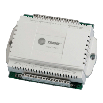
- Page 1 Installation and Operation Tracer ZN517 Unitary Controller CNT-SVX12C-EN...
- Page 3 Installation and Operation Tracer ZN517 ™ Unitary Controller CNT-SVX12C-EN April 2005...
- Page 5 Although Trane has tested the hardware and software described in this guide, no guarantee is offered that the hardware and software are error free. Trane reserves the right to revise this publication at any time and to make changes to its content without obligation to notify any per- son of such revision or change.
- Page 6 NOTICE: Warnings and Cautions appear at appropriate sections throughout this manual. Read these carefully: WARNING Indicates a potentially hazardous situation, which, if not avoided, could result in death or serious injury. CAUTION Indicates a potentially hazardous situation, which, if not avoided, may result in minor or moderate injury. It may also be used to alert against unsafe practices.
-
Page 7: Table Of Contents
Table of contents Chapter 1 Overview and specifications ....1 Product description ......... . 1 Dimensions . - Page 8 Table of contents Analog inputs for 2-heat/2-cool applications ..... 15 AI1: Universal 4–20 mA ........15 AI2: Outdoor air temperature or generic temperature .
- Page 9 Table of contents AI1: Universal 4–20 mA ........33 AI2: Outdoor air temperature or generic temperature .
- Page 10 Table of contents AI2: Outdoor air temperature or generic temperature ..53 DAT: Discharge air temperature ......53 ZN: Zone temperature .
- Page 11 Table of contents Reverse action ......... . 68 Error deadband .
- Page 12 Table of contents CNT-SVX12C-EN...
-
Page 13: Chapter 1 Overview And Specifications
Overview and specifications This guide provides installation and configuration information for the Tracer ZN517 unitary controller, as well as a description of its operations. The overview includes a product description, specifications, and descrip- tions of ancillary products that may be necessary. -
Page 14: Clearances
50/60 Hz • 9 VA and 12 VA maximum per binary output utilized • Operating environment Operate a Tracer ZN517 unitary controller in an indoor environment that meets the following requirements: • Temperature: From –40°F to 160°F (–40°C to 70°C) •... - Page 15 Operating environment Figure 1. Plastic-cover model dimensions and clearances 1 in. (25 mm) 4 in 4 in (102 mm) (102 mm) 4 in (102 mm) 5.625 in 6.875 in 6.31 in. (143 mm) (175 mm) (160 mm) 5.375 in (137 mm) 2 in.
-
Page 16: Storage Environment
Chapter 1 Overview and specifications Storage environment If you are storing a Tracer ZN517 unitary controller for a substantial amount of time, store it in an indoor environment that meets the following requirements: • Temperature: From –40° to 185°F (–40° to 85°C) •... - Page 17 Factory default temperature setpoints Table 1. Factory default temperature setpoints Factory defaults Setpoints °F (°C) Heating setpoint high limit 105.0°F (40.6°C) Heating setpoint low limit 40.0°F (44.4°C) Discharge air limits High limit 170.6°F (77.0°C) Low limit 37.4°F (3.0°C) Control point high limit 150.8°F (66.0°C) Control point low limit 44.6°F (7.0°C)
-
Page 18: Additional Components
Power transformer A transformer providing 24 Vac is required to power the Tracer ZN517 unitary controller and associated output relays and valve and damper actuators (see “AC power wiring” on page 85). -
Page 19: Chapter 2 Mounting The Controller
Tracer ZN517 unitary controller. Location recommendations For rooftop and heat pump applications, the controller can be mounted inside the unit or at a convenient location inside the building. Trane recommends locating the Tracer ZN517 unitary controller: • Near the controlled piece of equipment to reduce wiring costs •... -
Page 20: Mounting Recommendations
Mounting recommendations are as follows: IMPORTANT Mount the Tracer ZN517 unitary controller with the cover on to avoid the possibility of damaging the circuit board during installation. Mount the controller in any direction, other than with the front of the •... -
Page 21: Chapter 3 Applications For The 2-Heat/2-Cool Configuration
This chapter provides information for wiring input and output terminals and setting DIP switches for typical 2-heat/2-cool applications. The func- tion of inputs and outputs is also defined for these applications. The types of 2-heat/2-cool applications supported by the Tracer ZN517 unitary controller are: •... -
Page 22: Wiring Requirements And Options
20 * In order to use this function, the economizing function must be enabled. Figure 4 on page 11 shows a wiring diagram for the Tracer ZN517 that includes all required and all optional components for 2-heat/2-cool appli- cations. - Page 23 Wiring requirements and options Figure 4. Wiring diagram for 2-heat/2-cool applications Power* Tri-state modulating Compressor 1 contactor economizer (optional) Compressor 2 contactor Heat stage 1 Common Heat stage 2 24 Vac Y1 Y2 W1 W2 Generic binary output (optional) GND 24V OPN CLS 5NO 5COM STATUS HVAC UNIT...
-
Page 24: Dip Switch Settings
Chapter 3 Applications for the 2-heat/2-cool configuration DIP switch settings Set the DIP switches on the circuit board for the 2-heat/2-cool configura- tion. The correct settings are shown in Figure 5. Figure 5. DIP switch settings for the 2-heat/2-cool configuration O N D I P 2-heat/2-cool without economizer... -
Page 25: Binary Outputs For 2-Heat/2-Cool Applications
• Exhaust • The Tracer ZN517 controller has eight binary outputs. Each binary out- put is a relay with a rating of 12 VA. Table 5 describes the function of each output for 2-heat/2-cool applications. Table 5. Binary outputs for 2-heat/2-cool applications... -
Page 26: Overriding Binary Outputs
Binary inputs for 2-heat/2-cool applications The Tracer ZN517 unitary controller has two binary inputs. Each binary input associates an input signal of 0 Vac with open contacts and 24 Vac with closed contacts. Table 6 gives the function of each binary input for 2 heat/2 cool applications. -
Page 27: Analog Inputs For 2-Heat/2-Cool Applications
Analog inputs for 2-heat/2-cool applications Analog inputs for 2-heat/2-cool applications The Tracer ZN517 controller has five analog inputs. Table 7 describes the function of each input for 2-heat/2-cool applications. Each function is explained in the succeeding paragraphs. For an explanation of the diag- nostics generated by each analog input, see “Table of diagnostics”... - Page 28 Figure 7. AI1 terminal wiring: RH measurement Tracer ZN517 RH sensor – Figure Note: The +20 terminal provides 20 ±2 Vdc that is used to power a Trane RH sensor (part numbers 4190 1109, 4190 7011, 4190 7012, 4190 7014). CNT-SVX12C-EN...
-
Page 29: Ai2: Outdoor Air Temperature Or Generic Temperature
10 kΩ thermistor wired to analog input AI2. The generic tempera- ture input can be used with any Trane 10 kΩ thermistor. The thermistor can be placed in any location and has no effect on the operation of the con- troller. -
Page 30: Zn: Zone Temperature
The ZN analog input functions as the local (hard-wired) zone temperature input. The controller receives the temperature as a resistance signal from a 10 kΩ thermistor in a standard Trane zone sensor wired to analog input ZN. A communicated zone temperature value via the LonTalk communi- cations link can also be used for controllers operating on a BAS. -
Page 31: Chapter 4 Sequence Of Operations For The 2-Heat/2-Cool
Power-up sequence When 24 Vac power is initially applied to the Tracer ZN517 unitary con- troller, the following sequence occurs: 1. The Status (green) LED goes on. -
Page 32: Cascade Zone Control
Occupancy modes can be controlled by any of the following: The state of the local (hard-wired) occupancy binary input BI1 (see • “BI1: Occupancy or generic” on page 50) A timed override request from a Trane zone sensor (see “Timed over- • ride control” on page 22) CNT-SVX12C-EN... -
Page 33: Occupied Mode
If a communicated occupancy request has been established and is no longer present, the controller reverts to the default (occupied) occupancy mode after 15 minutes (if no hard-wired occupancy request exists). The Tracer ZN517 has the following occupancy mode options: Occupied •... -
Page 34: Occupied Bypass Mode
The controller is placed in occupied bypass mode when the controller is operating in the unoccupied mode and either the timed override ON but- ton on the Trane zone sensor is pressed or the controller receives a com- municated occupied bypass signal from a BAS. In occupied bypass mode, the controller maintains the zone temperature based on the occupied heating or cooling setpoints. -
Page 35: Fan Operation
ZN517 for economizing (economizing will not function). Fan operation The Tracer ZN517 can be configured to run continuously at a single speed or to cycle on and off automatically. If configured for continuous opera- tion, the fan runs continuously during the occupied, occupied standby, and occupied bypass modes. -
Page 36: Discharge Air Tempering
Rover service tool to select Supply Air Tem- pering Enabled. Demand control ventilation The Tracer ZN517 unitary controller modulates the outside air damper position in direct response to the CO level, regulating the amount of out- door air allowed to enter. -
Page 37: Filter-Maintenance Timer
Unit protection strategies Filter-maintenance timer The filter-maintenance timer tracks the amount of time (in hours) that the fan is enabled. The Maintenance Required Timer Setpoint (Maint Req Time Setpoint), configured with the Rover service tool, is used to set the amount of time until maintenance (typically, a filter change) is needed. - Page 38 Chapter 4 Sequence of operations for the 2-heat/2-cool configuration CNT-SVX12C-EN...
-
Page 39: Chapter 5 Applications For The 4-Cool Configuration
DIP switches for typical 4-cool applications. The function of inputs and outputs is also defined for these applications. The types of 4-cool applications supported by the Tracer ZN517 unitary controller are rooftop units with or without economizers. CNT-SVX12C-EN... -
Page 40: Wiring Requirements And Options
Chapter 5 Applications for the 4-cool configuration Wiring requirements and options Table 9 shows required controller inputs for minimal proper operation of all 4-cool applications. Table 9. Required controller inputs for all 4-cool applications For more information, Function Input source see: 24 Vac power Terminals: GND, 24 V... - Page 41 Wiring requirements and options Figure 9. Wiring diagram for 4-cool applications Power* Tri-state modulating Compressor 1 contactor economizer (optional) Compressor 2 contactor Compressor 3 contactor Common Compressor 4 contactor 24 Vac Y3 Y4 Generic binary output (optional) GND 24V OPN CLS 5NO 5COM STATUS HVAC UNIT...
-
Page 42: Dip Switch Settings
Chapter 5 Applications for the 4-cool configuration DIP switch settings Set the DIP switches on the circuit board for the 4-cool configuration. The correct settings are shown in Figure 10. Figure 10. DIP switch settings for the 4-cool configuration O N D I P 4-cool without economizer 1 2 3 4... -
Page 43: Binary Outputs For 4-Cool Applications
Cool 4 • Exhaust fan The Tracer ZN517 controller has seven binary outputs. Each binary out- put is a relay with a rating of 12 VA. Table 11 describes the function of each output for 4-cool applications. Table 11. Binary outputs for 4-cool applications... -
Page 44: Binary Inputs For 4-Cool Applications
Chapter 5 Applications for the 4-cool configuration Binary inputs for 4-cool applications The Tracer ZN517 unitary controller has two binary inputs. Each binary input associates an input signal of 0 Vac with open contacts and 24 Vac with closed contacts. Table 12 gives the function of each binary input for 4-cool applications. -
Page 45: Analog Inputs For 4-Cool Applications
Analog inputs for 4-cool applications Analog inputs for 4-cool applications The Tracer ZN517 controller has five analog inputs. Table 13 describes the function of each input for 4-cool applications. Each function is explained in the succeeding paragraphs. For an explanation of the diag- nostics generated by each analog input, see “Table of diagnostics”... - Page 46 Figure 12. AI1 terminal wiring: RH measurement Tracer ZN517 RH sensor – Figure Note: The +20 terminal provides 20 ±2 Vdc that is used to power a Trane RH sensor (part numbers 4190 1109, 4190 7011, 4190 7012, 4190 7014). CNT-SVX12C-EN...
-
Page 47: Ai2: Outdoor Air Temperature Or Generic Temperature
10 kΩ thermistor wired to analog input AI2. The generic tempera- ture input can be used with any Trane 10 kΩ thermistor. The thermistor can be placed in any location and has no effect on the operation of the con- troller. -
Page 48: Zn: Zone Temperature
The ZN analog input functions as the local (hard-wired) zone temperature input. The controller receives the temperature as a resistance signal from a 10 kΩ thermistor in a standard Trane zone sensor wired to analog input ZN. A communicated zone temperature value via the LonTalk communi- cations link can also be used for controllers operating on a BAS. -
Page 49: Chapter 6 Sequence Of Operations For The 4-Cool
Power-up sequence When 24 Vac power is initially applied to the Tracer ZN517 unitary con- troller, the following sequence occurs: 1. The Status (green) LED goes on. -
Page 50: Cascade Zone Control
Occupancy modes can be controlled by any of the following: The state of the local (hard-wired) occupancy binary input BI1 (see • “BI1: Occupancy or generic” on page 32) A timed override request from a Trane zone sensor (see “Timed over- • ride control” on page 40) CNT-SVX12C-EN... -
Page 51: Occupied Mode
If a communicated occupancy request has been established and is no longer present, the controller reverts to the default (occupied) occupancy mode after 15 minutes (if no hard-wired occupancy request exists). The Tracer ZN517 has the following occupancy mode options: Occupied •... -
Page 52: Occupied Bypass Mode
The controller is placed in occupied bypass mode when the controller is operating in the unoccupied mode and either the timed override ON but- ton on the Trane zone sensor is pressed or the controller receives a com- municated occupied bypass signal from a BAS. In occupied bypass mode, the controller maintains the zone temperature based on the occupied heating or cooling setpoints. -
Page 53: Fan Operation
ZN517 for economizing (economizing will not function). Fan operation The Tracer ZN517 can be configured to run continuously at a single speed or to cycle on and off automatically. If configured for continuous opera- tion, the fan runs continuously during the occupied, occupied standby, and occupied bypass modes. -
Page 54: Discharge Air Tempering
Rover service tool to select Supply Air Tem- pering Enabled. Demand control ventilation The Tracer ZN517 unitary controller modulates the outside air damper position in direct response to the CO level, regulating the amount of out- door air allowed to enter. -
Page 55: Filter-Maintenance Timer
Unit protection strategies Filter-maintenance timer The filter-maintenance timer tracks the amount of time (in hours) that the fan is enabled. The Maintenance Required Timer Setpoint (Maint Req Time Setpoint), configured with the Rover service tool, is used to set the amount of time until maintenance (typically, a filter change) is needed. - Page 56 Chapter 6 Sequence of operations for the 4-cool configuration CNT-SVX12C-EN...
-
Page 57: Chapter 7 Applications For The Heat Pump Configuration
DIP switches for typical heat pump applications. The function of inputs and outputs is also defined for these applications. The types of heat pump applications supported by the Tracer ZN517 uni- tary controller are heat pumps with: •... -
Page 58: Wiring Requirements And Options
Chapter 7 Applications for the heat pump configuration Wiring requirements and options Table 15 shows required controller inputs for minimal proper operation of all heat pump applications. Table 15. Required controller inputs for proper operation For more information, Function Input source see: 24 Vac power Terminals: GND, 24 V... - Page 59 Wiring requirements and options Figure 14. Wiring diagram for heat pump applications Power* Tri-state modulating Compressor 1 contactor economizer Compressor 2 contactor (optional) Reversing valve Common Auxiliary heat 24 Vac Y1 Y2 Generic binary output (optional) GND 24V OPN CLS 5NO 5COM STATUS HVAC UNIT...
-
Page 60: Dip Switch Settings
Chapter 7 Applications for the heat pump configuration DIP switch settings Set the DIP switches on the circuit board for the heat pump configura- tion. The correct settings are shown in Figure 15. Figure 15. DIP switch settings for heat pump configuration O N D I P Heat pump without economizer... -
Page 61: Binary Outputs For Heat Pump Applications
Auxiliary heat Exhaust fan • The Tracer ZN517 controller has eight binary outputs. Each binary out- put is a relay with a rating of 12 VA. Table 17 describes the function of each output for heat pump applications. Table 17. Binary outputs for 2-heat/2-cool applications... -
Page 62: Binary Inputs For Heat Pump Applications
Binary inputs for heat pump applications The Tracer ZN517 unitary controller has two binary inputs. Each binary input associates an input signal of 0 Vac with open contacts and 24 Vac with closed contacts. Table 18 gives the function of each binary input for 4-cool applications. -
Page 63: Analog Inputs For Heat Pump Applications
Analog inputs for heat pump applications The Tracer ZN517 controller has five analog inputs. Table 19 describes the function of each input for heat pump applications. Each function is explained in the succeeding paragraphs. For an explanation of the diag- nostics generated by each analog input, see “Table of diagnostics”... - Page 64 Figure 17. AI1 terminal wiring: RH measurement Tracer ZN517 RH sensor – Figure Note: The +20 terminal provides 20 ±2 Vdc that is used to power a Trane RH sensor (part numbers 4190 1109, 4190 7011, 4190 7012, 4190 7014). CNT-SVX12C-EN...
-
Page 65: Ai2: Outdoor Air Temperature Or Generic Temperature
10 kΩ thermistor wired to analog input AI2. The generic tempera- ture input can be used with any Trane 10 kΩ thermistor. The thermistor can be placed in any location and has no effect on the operation of the con- troller. -
Page 66: Zn: Zone Temperature
The ZN analog input functions as the local (hard-wired) zone temperature input. The controller receives the temperature as a resistance signal from a 10 kΩ thermistor in a standard Trane zone sensor wired to analog input ZN. A communicated zone temperature value via the LonTalk communi- cations link can also be used for controllers operating on a BAS. -
Page 67: Chapter 8 Sequence Of Operations For The Heat Pump
This chapter dis- cusses many of the operational sequences used to accomplish this goal. Power-up sequence When 24 Vac power is initially applied to the Tracer ZN517 unitary con- troller, the following sequence occurs: 1. The Status (green) LED goes on. -
Page 68: Cascade Zone Control
Occupancy modes can be controlled by any of the following: The state of the local (hard-wired) occupancy binary input BI1 (see • “BI1: Occupancy or generic” on page 50) A timed override request from a Trane zone sensor (see “Timed over- • ride control” on page 58) CNT-SVX12C-EN... -
Page 69: Occupied Mode
If a communicated occupancy request has been established and is no longer present, the controller reverts to the default (occupied) occupancy mode after 15 minutes (if no hard-wired occupancy request exists). The Tracer ZN517 has the following occupancy mode options: Occupied •... -
Page 70: Occupied Bypass Mode
The controller is placed in occupied bypass mode when the controller is operating in the unoccupied mode and either the timed override ON but- ton on the Trane zone sensor is pressed or the controller receives a com- municated occupied bypass signal from a BAS. In occupied bypass mode, the controller maintains the zone temperature based on the occupied heating or cooling setpoints. -
Page 71: Heating Or Cooling Mode
Fan operation The Tracer ZN517 can be configured to run continuously at a single speed or to cycle on and off automatically. If configured for continuous opera- tion, the fan runs continuously during the occupied, occupied standby, and occupied bypass modes. -
Page 72: Economizing
Economizing Economizing (also referred to as “free cooling”) uses outside air for cool- ing. The Tracer ZN517 provides two triac (3-wire floating point) outputs to control the damper actuator. One output opens the actuator; the other closes it. The controller also provides analog inputs for both a discharge air temperature sensor and an outside air temperature sensor. -
Page 73: Peer-To-Peer Communication
100% open. Peer-to-peer communication Tracer ZN517 unitary controllers have the ability to share data with other LonTalk-based controllers. Multiple controllers can be bound as peers, using the Rover service tool, to share: •... -
Page 74: Fan Off Delay
Chapter 8 Sequence of operations for the heat pump configuration The controller compares the fan-run time to Maintenance Required Timer Setpoint. Once the setpoint is reached, the controller generates a Mainte- nance Required diagnostic. When the diagnostic is cleared, the controller resets the filter-maintenance timer to zero, and the timer begins accumu- lating fan-run time again. -
Page 75: Chapter 9 Pid Control
Chapter 9 PID control This chapter will help you set up, tune, and troubleshoot proportional, integral, derivative (PID) control loops used in the Tracer ZN517 unitary controller. For more information about PID loops, see BAS-APG002, PID Control in Tracer Multi-Purpose Controllers. -
Page 76: Pid Calculations
This prevents the system from over-reacting to minor changes, but can potentially slow the system down. The recommended range for the integral calculation in the Tracer ZN517 is 1–10. Restore PID factory defaults by clicking the Use Defaults button. -
Page 77: Derivative Calculation
Sampling frequency Figure 20. Integral output added to proportional output Error ≠ 0 Error = 0 Proportional + integral output if proportional Proportional + integral output has gone to zero output Proportional-only output Time Derivative calculation The derivative calculation responds to the change in error. In other words, it responds to how quickly the measured value is approaching set- point. - Page 78 Chapter 9 PID control measured value. The system may miss important information and reach setpoint slowly or not at all. Figure 21 and Figure 22 show how aliasing can affect system response. In Figure 21 the sampling frequency is too slow. Because of this, many of the actual changes in duct static pressure are missed.
- Page 79 Sampling frequency The control system should always wait to process the result of a change before making another change. Figure 23 shows the process variable if sampling times are too fast, acceptable, and barely acceptable. If the sampling frequency is too fast (2 seconds), the process variable begins to oscillate and finally destabilizes because the PID loop output drives the actuator to extremes.
-
Page 80: Pid Loop Action
Chapter 9 PID control PID loop action The action of a PID loop determines how it reacts to a change in the pro- cess variable (such as a room temperature). A controller using direct action increases the output when the process variable increases. A con- troller using reverse action decreases the output when the process vari- able increases. -
Page 81: Error Deadband
Error deadband Error deadband Error deadband is typically used to minimize actuator activity. It can also be used to allow for some “slop” in the system sensors and actuator mechanics. Error deadband prevents the PID output from changing if the absolute value of the error is less than the error deadband. - Page 82 Chapter 9 PID control piece of equipment contributes a set amount to the final output. When setting the error deadband for staged outputs, the main goal is to reduce equipment cycling. Follow these guidelines when adjusting the error deadband: • Ask how tight control should be.
-
Page 83: Other Pid Settings
Other PID settings Other PID settings You can also use these settings to manage PID loops: Proportional bias, which takes the place of derivative gain in propor- • tional-only control Minimum and maximum output, which limit the range of output of •... -
Page 84: Tips For Specific Problems
Chapter 9 PID control Tips for specific problems Table 21 provides tips for troubleshooting specific problems. Table 21. Tips for specific problems Problem Tips Measured value is cycling • Slow the sampling frequency around setpoint • Decrease PID gains Overshooting setpoint Reduce gains Undershooting setpoint Increase gains... -
Page 85: Chapter 10 Status Indicators For Operation And Communication
This chapter describes the operation and communication status indica- tors on the Tracer ZN517 unitary controller, including: • A description of the location and function of the Test button and Ser- vice Pin button and the light-emitting diodes (LEDs) •... -
Page 86: Manual Output Test
Chapter 10 Status indicators for operation and communication Manual output test The manual output test sequentially turns off and on all binary outputs to verify their operation. The test overrides normal operation of the con- troller, which is suspended while the test is being performed. Use the manual output test to: •... - Page 87 Service Pin button Table 22. Manual output test sequence for 2-heat/2-cool configurations Begins test mode Fan on Compressor 1 Compressor 2 Heat 1 Heat 2 Outdoor air damper Generic/exhaust fan/occupancy Exit At the beginning of Step 2, the controller attempts to clear all diagnostics. This step exits the manual output test and initiate a reset to restore the controller to normal operation.
-
Page 88: Interpreting Leds
This step exits the manual output test and initiate a reset to restore the controller to normal operation. Interpreting LEDs The red LED on the Tracer ZN517 unitary controller (see Figure 27 on page 73) indicates whether the controller is not working properly (see Table 25). - Page 89 Interpreting LEDs The green LED on the Tracer ZN517 unitary controller (see Figure 27 on page 73) indicates whether the controller has power applied to it and if the controller is in manual test mode (see Table 26). Table 26. Green LED: Status indicator...
-
Page 90: Diagnostics
Diagnostic types The Tracer ZN517 has two types of diagnostics: informational and auto- matic (also referred to as nonlatching). Informational diagnostics provide information about the status of the controller. They do not affect machine operation. -
Page 91: Table Of Diagnostics
Diagnostics Table of diagnostics Table 28 describes each diagnostic that can be generated by the Tracer ZN517. Table 28. Diagnostics for the ZN517 unitary controller Diagnostic Diagnostic Probable cause Consequences type P Normal Default value until power-up None control wait expires Normal Default value after power-up None... - Page 92 Chapter 10 Status indicators for operation and communication CNT-SVX12C-EN...
-
Page 93: Chapter 11 General Wiring Information
Chapter 11 General wiring information This chapter provides specifications and general information about wir- ing the Tracer ZN517 unitary controller. The controller requires wiring for: • Input/output terminals AC power to the controller • Communication-link wiring, if the controller is to communicate with a •... -
Page 94: Hvac Unit Electrical Circuit Wiring
The terminals labeled Rc and Rh are provided as inputs for 24 Vac power from the transformer(s) of the HVAC system. Note: The Tracer ZN517 is shipped from the factory with terminals Rc and Rh coupled with the jumper at J1 on the controller cir- cuit board. - Page 95 Input/output terminal wiring Figure 28. Location of J1 on Tracer ZN517 circuit board J1 (location of jumper for Rc, Rh terminals) Figure 29. Coupling and uncoupling terminals Rc and Rh for 24 Vac wiring of the HVAC unit For split systems...
-
Page 96: Chapter 11 General Wiring Information
Chapter 11 General wiring information Figure 30. Wiring for packaged heating and cooling units Primary Secondary, 24 Vac Tri-state modulating Compressor 1 contactor economizer Compressor 2 contactor (optional) Heat stage 1 Heat stage 2 24 Vac Y1 Y2 W1 W2 Generic binary output (dry contact) Figure 31. -
Page 97: Ac Power Wiring
Do not share 24 Vac between controllers. All wiring must comply with National Electrical Code and local codes. The ac power connections are in the top left corner of the Tracer ZN517 unitary controller (see Figure 32). Figure 32. Connecting ac power wires to the controller... -
Page 98: Communication-Link Wiring And Addressing
Chapter 11 General wiring information Communication-link wiring and addressing The Tracer ZN517 unitary controller communicates with a BAS and with other LonTalk controllers via a LonTalk communication link. For instruc- tions on LonTalk communication wiring and addressing, follow the requirements given in the Tracer Summit Hardware and Software Instal-... -
Page 99: Chapter 12 Troubleshooting
If you encounter operational problems with the Tracer ZN517, you must first perform initial troubleshooting steps; see “Initial troubleshooting” on page 88. After this procedure, consult the tables in “Diagnosing opera- tional problems”... -
Page 100: Initial Troubleshooting
“Manual output test” on page 74. cuit board prob- If the outputs on the controller do not behave as described in the manual output test (page 74), then you are likely to have a Tracer ZN517 circuit board problem. Diagnosing operational problems... - Page 101 For information about diagnostics, see Table 28 on page 79. No power to the con- If the controller does not have power, the unit fan does not operate. For the Tracer ZN517 troller controller to operate normally, it must have an input voltage of 24 Vac. If the green LED is off continuously, the controller does not have sufficient power or has failed.
- Page 102 Chapter 12 Troubleshooting Table 31. Heat does not energize Probable cause Explanation Unit wiring The wiring between the controller outputs and the electric heat contacts must be present and correct for normal electric heat operation. Refer to applicable wiring diagram. Failed end device Check electric heat element, including any auxiliary safety interlocks, to ensure proper operation.
- Page 103 Diagnosing operational problems Table 32. Outdoor air damper remains closed (Continued) Probable cause Explanation Unit configuration The controller must be properly configured based on the actual installed end devices and application. If the unit configuration does not match the actual end device, the outdoor air damper may not work correctly.
- Page 104 Chapter 12 Troubleshooting CNT-SVX12C-EN...
-
Page 105: Index
Index Numerics Exhaust fan output, 31 Fan off delay, 43 24 Vac wiring, 85 Fan operation, 41 Fan status, 43 2-heat/2-cool configuration Fan status input, 32 Analog inputs, 15–18 Filter-maintenance timer, 43 Binary inputs, 14 Generic binary input, 32 Binary output 5 (5NO/5COM/5NC), Generic binary output, 31 Manual output test sequence, 75 Binary outputs, 13–14... - Page 106 Index AI2 generic temperature Binary outputs Binary output 5 (exhaust fan, configuration, 17, 35, 53 2-heat/2-cool, 13–14 occupancy, or generic), 13, 31, Generic temperature, 17, 35, 53 4-cool, 31 Configuration options for binary Analog inputs, 2-heat/2-cool Configurations output 5 (5NO/5COM/5NC), 13, DAT (Discharge air 2-heat/2-cool, 9–25 31, 49...
- Page 107 Index Discharge air temperature HVAC split systems sensors, 6 Wiring, 82 Heat failure, troubleshooting, 90 Wiring diagram, 84 Discharge air tempering, 24, 42, 60 Heat pump applications, 45 HVAC unit electrical circuit wiring, Components, 49 82–84 Heat pump configuration Analog inputs, 51–54 Economizing, 17, 23, 35, 41, 53, 60 Binary inputs, 50 Equipment...
- Page 108 Index Error deadband, 69–70 Occupancy, 14, 32, 50 Integral calculation, 64 Table of options, 6 Occupancy modes, 2-heat/2-cool Managing with additional Zone humidity, 16, 34, 52 General, 20 settings, 71 Zone temperature, 6 Occupied, 21 Overview, 63 Sequence of operations, 2-heat/2- Occupied bypass, 22 Proportional calculation, 64 cool...
- Page 109 Index Service Pin button Fans, 89 Function, 74 Heat failure, 90 Zone temperature input Location, 73 Initial steps, 88 2-heat/2-cool configuration, 18 Outdoor air damper remains Setpoint, controlling with PID loop, 4-cool configuration, 36 closed, 90 Heat pump configuration, 54 Outdoor air damper remains Settings open, 91...
- Page 110 Index CNT-SVX12C-EN...
- Page 111 For more information contact your local Trane Trane has a policy of continuous product and product data improvement and reserves the right to office or e-mail us at comfort@trane.com change design and specifications without notice. Only qualified technicians should perform the installa-...
Need help?
Do you have a question about the Tracer ZN517 and is the answer not in the manual?
Questions and answers