Advertisement
Quick Links
Installation, Operation, and Maintenance
Symbio™ 400–B/500 Programmable
Controllers
Water Source Heat Pump (WSHP)
Only qualified personnel should install and service the equipment. The installation, starting up, and servicing of heating, ventilating, and air-conditioning equipment
can be hazardous and requires specific knowledge and training. Improperly installed, adjusted or altered equipment by an unqualified person could result in death or
serious injury. When working on the equipment, observe all precautions in the literature and on the tags, stickers, and labels that are attached to the equipment.
December 2024
SAFETY WARNING
BAS-SVX092C-EN
Advertisement

Related Manuals for Trane Symbio 400-B


Summary of Contents for Trane Symbio 400-B
- Page 1 Installation, Operation, and Maintenance Symbio™ 400–B/500 Programmable Controllers Water Source Heat Pump (WSHP) SAFETY WARNING Only qualified personnel should install and service the equipment. The installation, starting up, and servicing of heating, ventilating, and air-conditioning equipment can be hazardous and requires specific knowledge and training. Improperly installed, adjusted or altered equipment by an unqualified person could result in death or serious injury.
- Page 2 Chlorine, Fluorine and Carbon (CFCs) and those containing Hydrogen, Chlorine, Fluorine and Carbon (HCFCs). Not all refrigerants containing these compounds have the same potential impact to the environment. Trane advocates the responsible handling of all refrigerants.
- Page 3 454B, contact your local representative. Copyright This document and the information in it are the property of Trane, and may not be used or reproduced in whole or in part without written permission. Trane reserves the right to revise this publication at any time, and to make changes to its content without obligation to notify any person of such revision or change.
- Page 4 Introduction Revision History • Added binary input LLID and leak detection/refrigerant sensor information across the document. • Added regulatory information in front matter and Additional Information chapter. • Updated wiring diagrams. BAS-SVX092C-EN...
- Page 5 Table of Contents General Information............. 8 Overview .
- Page 6 Table of Contents Wiring Installation ............. . 32 Unitary Leak Detection Systems (LDS) .
- Page 7 Table of Contents Diagnostics ..............59 Override Outputs .
- Page 8 Symbio 400–B/500 Controller with specific operation description for Water Source Heat Pump (WSHP). Note: LonTalk Communications are not supported on Symbio 210/210e/400–B/500. Agency Listings and Compliance The European Union (EU) Declaration of Conformity is available from your local Trane® office. BAS-SVX092C-EN...
- Page 9 In addition, BACnet® defines a number of application services that are used to interact with objects in a BACnet® device. BACnet Testing Laboratory (BTL) Certification The Symbio 400–B/500 is BTL certified as a B-BC profile device. A complete list of Trane certified devices is available at www.bacnetinternational.org. BAS-SVX092C-EN...
- Page 10 • The Symbio 400–B is BTL certified as a B-BC profile device. A complete list of Trane certified devices is available at www.bacnetinternational.org. Note: The Symbio 500 programmable controller supports being a BBMD. This is a specific functionality and is different than the profile certification. The Symbio 500 cannot be a router.
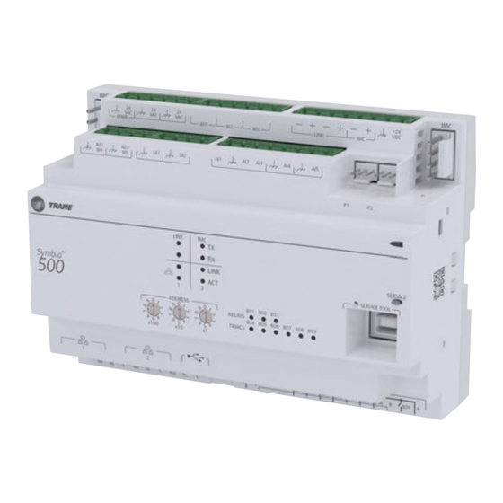
- Page 11 Specifications and Dimensions Figure 1. Symbio 400–B/500 dimensions 2.17 in. 5.65 in. (143.5 mm) [8 units*] (55 mm) 1.73 in. (44 mm) 4.00 in. (101.6 mm) *DIN Standard 43 880, Built-in Equipment for Electrical Installation. Overall Dimensions and Related Mounting Dimensions. For mounting and clearance recommendations, refer to Symbio 500 Programmable Controller Installation, Operation, and Maintenance Manual (BAS-SVX090*-EN).
- Page 12 10kΩ – Type II, 10kΩ – Type These inputs can be configured for timed override capability. III, 2252Ω – Type II, 20kΩ – Supports *, ** for Trane Zone Sensors. Thermistor Type IV, 100 kΩ Balco™ (Ni-Fe) 1kΩ, 385 (Pt) Analog Input (AI1 to 1kΩ, 375 (Pt) 1kΩ, 672 (Ni)
- Page 13 Device Connections Table 2. Device connections (continued) Quan- tity Types Range Connection Notes Analog Output / Linear Current 0 - 20mA Binary Input (AO1/ Linear Voltage 0 - 10Vdc BI4 and AO2/ BI5) Each termination must be configured as either an analog output or Binary Input Dry contact binary input.
- Page 14 Note: Additional components are not included with the Symbio 400–B/500 Controller. Water, Discharge, and Outdoor Air Temperature Sensors Temperature sensors must be Trane 10 kΩ (at 25°C) thermistors. Entering water and discharge air inputs can use a sealed temperature sensor (part numbers 4190 1100 and 4190 1133).
- Page 15 4–20 mA output, where 4 mA is 0% RH and 20 mA is 100% RH. The controller provides 24 Vdc to power the zone humidity sensor. Note: As an option, the Symbio 400–B/500 controller can receive humidity from a Trane Air-fi™ WCS Wireless Sensor with Humidity (WCS-SH Relative Humidity module part number X13790973030).
- Page 16 Electric Heat Boiler-less Heat Pump Cooling Only The following table lists 1 or 2 compressor control with discrete 1– or 2–speed fans based on Trane GE units. Table 5. Factory programmed terminations for Trane GE units Symbio 400–B/ 500 Controller...
- Page 17 When Hot Gas Reheat and Electric Heat are present on the same WSHP, Electric Heat will be moved to BO1 on XM32. The following table lists single compressor control with variable speed fan based on Trane EX/DX units. Table 6. Factory programmed terminations for single compressor control for Trane EX/DX units Symbio 400–B/...
- Page 18 Typical Applications and Terminations Table 6. Factory programmed terminations for single compressor control for Trane EX/DX units (continued) Symbio 400–B/ 500 Controller Inputs/Outputs/Communication Factory Programmed Assumed Terminations Terminations AO- Variable Speed Fan Control AO1/BI4 Analog Outputs/Binary Inputs AO2/BI5 BI- Fan Status...
- Page 19 Symbio 400–B/500 controller receives the space temperature as a resistance signal from a 10 kΩ thermistor in a standard Trane space temperature sensor that is wired to analog input AI1. A space temperature value communicated by means of a BACnet link, can be used for controllers operating on a BAS.
- Page 20 LLID Input LLID input is a low voltage binary input used for the purpose of connecting a Trane refrigerant monitor. BI7; Refrigerant Leak Detection Sensor Refrigerant Leak Detection Sensor BI7 functions as a local hardwired input for Trane refrigerant monitor on units which require leak detection sensing and mitigation sequences.
- Page 21 Space Temperature Local. Terminals: AI1, Ground AI1; Space Temperature Entering Water Temperature (Required Only for Units With Auto- AI5; Entering Water Temperature Terminal: AI5 or communicated changeover. Symbio 500 Wiring Diagrams Figure 2. Common input/sensor connections (Trane EX units only) BAS-SVX092C-EN...
- Page 22 Typical Applications and Terminations Figure 3. 2–position ventilation economizer (Trane EX units only) XFRM XFRM XFRM XFRM BI 1 BI 2 BI 3 LINK LINK LINK LINK UI 1 UI 1 UI 2 AI 1 AI 1 AI 2 AI 2...
- Page 23 Typical Applications and Terminations Figure 4. Common input/sensor connections (Trane GE units only) BAS-SVX092C-EN...
- Page 24 Typical Applications and Terminations Figure 5. 2–position ventilation economizer (GE units only) IM C IM C + 24 XFRM BI 1 BI 2 BI 3 LINK AI 4 AI 5 UI 1 UI 2 AI 1 AI 2 AI 3 BI 4 BI 5 LINK IMC...
- Page 25 Typical Applications and Terminations Figure 6. Variable speed supply fan IM C IM C + 24 XFRM BI 1 BI 2 BI 3 LINK AI 4 AI 5 UI 1 UI 2 AI 1 AI 2 AI 3 BI 4 BI 5 LINK IMC SERVI C E...
- Page 26 Typical Applications and Terminations Figure 7. Relative humidity Symbio 500 to RH 4-20 mA 24 VDC Figure 8. P1 condensate 24 Vac Relay Condensate Sensor For eld applications, an unused binary input can be used. BAS-SVX092C-EN...
- Page 27 Typical Applications and Terminations Symbio 400–B Wiring Diagrams Figure 9. Common input/sensor connections for GE units only BAS-SVX092C-EN...
- Page 28 Typical Applications and Terminations Figure 10. 2–position ventilation economizer for Trane EX and DX units 6 pin Phoenix Phoenix 5 pin Phoenix Phoenix Phoenix Service On DX units, BO4 is Compressor Enable 3 Pin 3 Pin Mini Mini BO5 is Compressor Step On EX/DX units, BO1 is fan start/stop.
- Page 29 Typical Applications and Terminations Figure 11. Common input/sensor connections for EX and DX units BAS-SVX092C-EN...
- Page 30 Typical Applications and Terminations Figure 12. 2–position ventilation economizer for GE units only 6 pin Phoenix Phoenix 5 pin Phoenix Phoenix Phoenix Service 3 Pin 3 Pin Mini Mini Comm - Address Comm + 1 2 3 24VDC J14 - JST 14 13 12 11 10 9 8 7 6 5 4 3 2 1 Phoenix...
- Page 31 Typical Applications and Terminations Figure 13. Variable speed supply fan Variable Supply Fan Motor Fan Status Speed 6 pin Phoenix Phoenix 5 pin Phoenix Phoenix Phoenix Service 3 Pin 3 Pin Mini Mini Comm - Address Comm + 1 2 3 24VDC J14 - JST 14 13 12 11 10 9 8 7 6 5 4...
- Page 32 Wiring Installation The Symbio 400–B/500 Controller can be installed on a BACnet MS/TP link, or with the Trane ® Wireless Communication Interface (WCI), which enables wireless communication. All wiring must comply with the National Electrical Code (NEC™) and local electrical codes.
- Page 33 Wiring Installation Replacing a Binary Input LLID used for A2L Refrigerant Monitor Note: This process must be followed with the help of a technician with Tracer® TU. 1. Connect to a controller with TU v11.9 or higher. 2. Verify the controller has A2L points by navigating to the Equipment Utility/Configuration and verifying the A2l refrigerant sensor is installed.
- Page 34 Wiring Installation 5. Reconnect the USB cable and start the Tracer TU. 6. Navigate to the Status Utility/Controller Status. As the device is brand new, it will have a default address of 0. Note: In the following figure Symbio™ discovered LLID-BI at address 0 and is expecting the LLID-BI to be at address 98.
- Page 35 BACnet/IP Over Wired Ethernet Communications Wired Ethernet is only an option on the Symbio 500 controller. Use daisy chain, star, or ring topologies. BACnet/IP Over Wi-Fi Communications Symbio 500 can communicate wirelessly through an optional Trane Wi-Fi module on the USB port. BAS-SVX092C-EN...
- Page 36 X13651743002 Wi-Fi Field Installed Kit, 2.9 m cable, 70C Air-Fi Wireless BACnet® Communications Symbio 400–B/500 can communicate wirelessly to the Trane Tracer SC+ and zone sensors through the Trane Air-Fi Wireless system (BACnet/Zigbee). Wireless Air-Fi communications are the preferred method of communicating to the SC+. Trane Air-Fi is a factory or field installed option.
- Page 37 Wiring Installation • Ensure that 24 Vac power supplies are consistent in regards to grounding. Avoid sharing 24 Vac between controllers. • Avoid over tightening cable ties and other forms of cable wraps. This can damage the wires inside the cable. •...
- Page 38 Wiring Installation Figure 17. Setting the rotary address Use a 1/8 inch (3.2 mm) flathead screwdriver to set rotary address dials. These dials rotate in either direction. MAC Address The MAC Address is required by the RS-485 communication protocol on which BACnet operates. Valid MAC addresses are 001 to 127 for BACnet.
- Page 39 Wiring Installation The three values are joined together to form the BACnet device ID for the unit controller as shown in the following table. Table 9. Calculating the BACnet Device ID Tracer SC+ rotary switch value (21) Tracer SC+ BACnet MS/TP link number (1) Unit controller MAC address (38) BACnet Device ID: 211038...
- Page 40 Wiring Installation Important: • Route the USB cable to avoid damage by panel doors or similar obstructions. Severely kinked, cut, or otherwise damaged cables should be replaced even if they appear to be in working order. • Do not route the USB cable in proximity with electrically noisy cables such as AC power (24, 120, 240 VAC), or wires that are switched by relays or contactors.
- Page 41 Transformer Recommendations The Symbio 400-B/500 controller can be powered with 24 Vac or 24 Vdc. You must use a 24 Vac power supply for proper operation of the binary inputs, which require 24 Vac detection, and also to use the spare 24 Vac outputs to power relays and TRIACS.
- Page 42 Wiring Installation Figure 20. Symbio 400-B/500 transformer A pigtail connection may be neces- sary between earth ground and/or enclosure ground if the device is 24 VAC not grounded through one leg of transformer the transformer wiring. Alternative earth ground method.
- Page 43 LEDs LED Locations The Symbio controllers have the following LEDs located on the front (refer to the following illustration): • Marquee LED • Communication Status LEDs and IMC Status LEDs • Service Button LED • Binary Output Relay (3)/TRIAC (9) Status LEDs (only the Symbio 400–B) Figure 21.
- Page 44 LEDs Figure 22. Symbio 400/B LED Locations 6 pin Phoenix Phoenix 5 pin Phoenix Phoenix Phoenix Service 3 Pin 3 Pin Mini Mini Comm - Address Comm + 1 2 3 24VDC J14 - JST 14 13 12 11 10 9 8 7 6 5 4 3 2 1 Phoenix 14 Pin AMP...
- Page 45 LEDs Table 10. LED activities and troubleshooting tips (continued) Blinks at the data transfer rate when TX blinks green. the unit transfers data to other TX LED: Regardless of connectivity devices on the link. or not, this LED will constantly blink as it continually looks for devices to Blinks at the data transfer rate when communicate to.
- Page 46 LEDs Table 11. Marquee LED status and error codes (continued) Message Description Action by User LED Blink Pattern Field Format Reformatting the field file system. None- normal operation Starting Update Starting the firmware update process. None- normal operation Locating Firmware File Attempting to locate a firmware update file.
- Page 47 LEDs Table 11. Marquee LED status and error codes (continued) Message Description Action by User LED Blink Pattern Field Mount Fail Failed to mount the field file system. Replace controller. Bad Update Method Don’t know what our update method is. Contact technical support.
- Page 48 • The state of the local (hard wired) occupancy binary input BI1. • A timed override request from a Trane zone sensor. • A communicated signal from either a Tracer SC+ or BAS. A communicated request, from either a Tracer SC+ or BAS, takes precedence over local requests. If a communicated occupancy request has been established and is no longer present, the controller reverts to the default (occupied) occupancy mode after 15 minutes (if no hard wired occupancy request exists).
- Page 49 Sequence of Operations Table 12. Occupancy modes Occupancy Request Occupancy Resultant Occupancy– (MV/6) Input (B/1) Occupancy Status (MV/7) TOV Initiated Occupied Occupied Occupied Occupied Standby Unoccupied Bypass Occupied Occupied Occupied Bypass Occupied Standby Unoccupied Occupied Bypass Unoccupied Unoccupied Occupied Bypass Occupied Standby Occupied Standby Occupied Bypass...
- Page 50 Sequence of Operations • The controller is operating in the unoccupied mode and the timed override ON button on the Trane zone sensor is pressed (see Timed Override Control below). • The controller receives an occupied bypass signal from a BAS.
- Page 51 Sequence of Operations are not being met. The fan mode request can be either communicated through a BAS or hard wired to the controller from a fan switch. In all configurations, the fan can be controlled off when the manual output test has been initiated or a latching diagnostic is present.
- Page 52 Sequence of Operations Table 13. Constant torque supply fan default settings Low Setting Minimum High Setting Scaling Factor Efficiency AV18, AV19, or AV20 Size Setting AV17 AV22 (Mode Dependent) GEVG 006 GEVG 009 GEVG 012 GEVG 015 GEVG 018 Standard Efficiency GEVG 024 GEVG 030 GEVG 036...
- Page 53 Sequence of Operations 1– and 2–Speed Fan Operation When using a 2-speed fan, the Symbio 400–B/500 controller can be configured for default operation by adjusting the Cooling Fan Speed Default and Heating Fan Speed Default. Both of these values are factory-installed and are set to AUTO.
- Page 54 Sequence of Operations When the above conditions have been met, Isolation Valve is opened for three (3) minutes, the EWT reading is recorded, and WSE operation feasibility is determined. The isolation valve remains open regardless. Sampling for Electric Heat Units For units equipped with electric heat and configured for boiler-less control, EWT is used to determine whether DX heating should be disabled and electric heat enabled.
- Page 55 Sequence of Operations Table 16. Coil icing Cooling Mode Control Action Economizer None Economizer and Stage-1 DX Disable Stage-1 DX Stage-1 and Stage-2 DX Disable DX Stages 1 and 2 Note: The fan remains ON during this operation. Low Leaving Air Protection This mode is activated during WSE operation and controlled by the discharge air sensor.
- Page 56 Sequence of Operations compressor units. Zone temperature is compared against active setpoints for compressor operation. OFF, pulse width modulation (PWM), or ON are how the compressor can be controlled. Note: When the control is in the dehumidification mode, only OFF and ON are valid compressor states. At startup or during mode transition, if both compressors are requested to run, Compressor 1 is energized first and Compressor 2 waits until the next control cycle (10 seconds) to energize.
- Page 57 Sequence of Operations To avoid sub-cooling the space if the reheat is not sized properly, or during certain system conditions, a low limit temperature is established to exit active dehumidification mode. The low limit is the active cooling setpoint in the Occupied and Unoccupied standby modes. In the Unoccupied mode, the default occupied cooling setpoint is used as the low limit.
- Page 58 Sequence of Operations modulate to maintain discharge air dehumidification setpoint (AV39 Dehumidification Discharge Air Setpoint BAS). When running in passive dehumidification mode “Dehumidification” will be reported by MV5 Heat Cool Mode Status. To exit passive dehumidification mode one of the following conditions must be met: •...
- Page 59 Operational Troubleshooting This section provides information about the various diagnostics and troubleshooting for the Symbio 400–B/500 controller. WARNING Live Electrical Components! Failure to follow all electrical safety precautions when exposed to live electrical components could result in death or serious injury. When it is necessary to work with live electrical components, have a qualified licensed electrician or other individual who has been properly trained in handling live electrical components perform these tasks.
- Page 60 Operational Troubleshooting Table 18. Symbio 400–B/500 controller diagnostics (continued) Diagnostic Unit Response Latching/non-latching Reset Filter Change Required Non-latching Communicated or manual • Fan Enabled reset is required • Valves Enabled The Filter Change Required diagnostic is generated when the fan run-time exceeds •...
- Page 61 Operational Troubleshooting point, either press the service pin to advance to the next step or stay in the current step for up to one (1) hour. After one (1) hour, the unit automatically returns to Normal Operation. For both manual output test options described above, the unit ignores mechanical safeties such as compressor delays and minimum on/off times.
- Page 62 Operational Troubleshooting BAS-SVX092C-EN...
- Page 63 Operational Troubleshooting Resetting Diagnostics The following methods describe resetting unit diagnostics: • High/Low Pressure Cutout • Manual Output Test • Cycling Power • Building Automation System (BAS) • Tracer TU Service Tool • Cycling the Fan Switch • Leak Detection Sensor High/Low Pressure Cutout The Symbio 400–B/500 controller includes a one-time automatic diagnostic reset function.
- Page 64 Operational Causes and Diagnostics Table 20. Symbio 400–B/500 controller diagnostic causes and diagnostics Diagnostic Probable Cause Fan Not Energizing The wiring between the Symbio 400–B/500 controller outputs, fan relays, and contacts must be present and correct for Unit Wiring normal fan operation. The fan motor and relay must be checked to ensure proper operation.
- Page 65 Operational Causes and Diagnostics Table 20. Symbio 400–B/500 controller diagnostic causes and diagnostics (continued) Diagnostic Probable Cause Ensure the valves are correctly configured, using the Tracer TU service tool, as normally open (NO) or normally closed (NC) Valve Configuration as dictated by the application. •...
- Page 66 Operational Causes and Diagnostics Table 20. Symbio 400–B/500 controller diagnostic causes and diagnostics (continued) Diagnostic Probable Cause Diagnostic Present Several diagnostics affect outdoor air damper operation. The Symbio 400–B/500 controller opens and closes the outdoor air damper based on the controller’s occupancy mode and Normal Operation fan status.
- Page 67 Additional Resources • Air-Fi Wireless System IOM (BAS-SVX40*-EN) • Air-Fi Network Design (BAS-SVX55*-EN) • Air Systems for the Tracer SC+ Application Guide (BAS-APG036*-EN) • BACnet/IP Wiring and Best Practices Application Guide (BAS-APG046*-EN) • BACnet MS-TP Wiring and Link Performance Best Practices and Troubleshooting Guide (BAS- SVX51*-EN) •...
- Page 68 For more information, please visit trane.com or tranetechnologies.com. Trane has a policy of continuous product and product data improvements and reserves the right to change design and specifications without notice. We are committed to using environmentally conscious print practices.
Need help?
Do you have a question about the Symbio 400-B and is the answer not in the manual?
Questions and answers