Table of Contents
Advertisement
Quick Links
Advertisement
Table of Contents

Related Manuals for Pro-face Xycom SXT1811


Summary of Contents for Pro-face Xycom SXT1811
- Page 1 SXT1811 FLAT PANEL INDUSTRIAL MONITOR FLAT PANEL INDUSTRIA Hardware Guide...
- Page 2 Revision Description Date Manual released 08/00 Manual updated 06/02 Xycom Automation Part Number 141285(B) Trademark Information Xycom Automation is a trademark of Xycom Automation, Inc. Brand or product names may be registered trademarks of their respective owners. Windows is a registered trademark of Microsoft Corporation in the United States and other countries.
-
Page 3: Table Of Contents
Table of Contents 1. Product Overview..…..................1-1 Product Features…………………………………………….……………………………………1-1 Standard SXT1811 Features…………………………………………………………………….1-1 Parts List…………………………………………………….……………………………………1-1 Standard SXT1811 Parts List…………………………………………………………………...1-1 Manual Overview…………………………………………….…………………………………..1-2 Text Conventions Used in this Manual …………………….……………………………………1-2 Product Dimensions ……………………………………….…………………………………….1-3 Front Panel Controls …………………………………………….……………………………1-3 Product Specifications and Ratings……..………………….……………………………………1-4 Environmental……...…….……………………………………………………………………1-4 Electrical ……………………………………………………………………………………...1-4 Front Panel/Enclosure ..…….…………………………….…………………………………..1-4 Regulatory Compliance ...………………………………...…………………………………..1-4 Safety Agency Approvals ………………….…………………………………………………1-4... -
Page 4: Product Overview
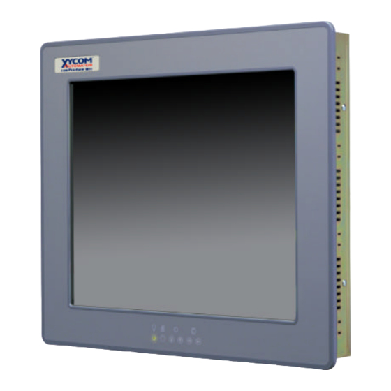
1. Product Overview Xycom Automation industrial monitors meet the rigorous requirements of the plant floor with high-resolution flat panel displays in a rugged housing with an optional resistive membrane touchscreen. The SXT1811 flat panel monitor delivers crisp, bright text and graphics with a low current draw, and it fits into panels that CRTs cannot. -
Page 5: Manual Overview
Manual Overview The manual is divided in the following chapters: • Chapter 1 – Product Overview • Chapter 2 – Installation • Chapter 3 – Monitor Settings • Chapter 4 – Hardware Text Conventions Used in this Manual Throughout this manual, certain terms are formatted in ways that indicate what type of object is being described. -
Page 6: Product Dimensions
Product Dimensions 3.35[85.09] 18.51[470.15] P OW E R ME NU S E L UP S E L DN DE C 15.70 I NC [398.78] S E T O F F in.[mm] Front Panel Controls The front panel controls, from left to right are Menu, Select, Increment, Decrement. Their use is detailed in Chapter 3—... -
Page 7: Product Specifications And Ratings
Product Specifications and Ratings Environmental Operating Nonoperating Thermal -20°C to 60°C (32°F to 122°F) 0°C to 50°C (32°F to 122°F) Humidity 20% to 80% RH, noncondensing 20% to 80% RH, noncondensing 15 g peak acceleration, 30 g peak acceleration, Shock 11 msec duration 11 msec duration Vibration,... -
Page 8: Installation
2. Installation Environmental Considerations The rugged design of the SXT1811 allows it to be installed in most industrial environments. Refer to the electrical and environmental specifications and tolerances (pg. 1-4) for more detailed information. System Power It is a good practice to use isolation transformers on the incoming AC power line to the system. -
Page 9: Electrical Noise
Electrical Noise Electrical noise is seldom responsible for damaging components, unless extremely high energy or high voltage levels are present. However, noise can cause temporary malfunctions that can result in hazardous machine operation in certain applications. Noise may be present only at certain times, may appear at widely spread intervals, or in some cases may exist continuously. -
Page 10: Panel Installation
sure that outside air is not brought inside the enclosure unless a fabric or other reliable filter is used. This filtration prevents conductive particles or other harmful contaminants from entering the enclosure. • Do not select a location near equipment that generates excessive electromagnetic interference (EMI) or radio frequency interface (RFI) (equipment such as high-power welding machines, induction heating equipment, and large motor starters). -
Page 11: Monitor Settings
3. Monitor Settings Mode and Image Adjustment Not all video controllers produce exactly the same video output levels or the same timing. The following procedure can be used to select the desired video mode as well as optimize your monitor’s image quality. When adjusting your monitor, the use of video test software such as DisplayMate for Windows by SONERA Technologies can be very beneficial. -
Page 12: Video Modes Supported
Video Modes Supported Mode Horizontal Sync Vertical Sync Dot Freq. Expansion Factor Rate (KHz) Rate (KHz) (MHz) Vertical Horizontal VESA VGA 31.5 25.175 (640x480) 37.9 31.500 37.5 31.500 43.3 36.000 IBM (720x400) 31.5 28.322 37.9 35.500 VESA SVGA 35.1 36.000 (800x600) 37.9 40.000... - Page 13 Color Adjust video color level Tint Adjust video tint level Sharpness Adjust video image sharpness level Video Adjustment** Video Type Change bandwidth to match the source (DVD/VCR) Frequency Adjust the image horizontal size Phase Fine tune the data sampling position (adjust image quality) Frequency&Phase* AUTO automatic detection of NTSC and PAL...
- Page 14 User Setting: User Timeout Adjust the OSD menu timeout period in a step of 5 seconds DPMS Disable/Enable the DPMS function Auto Source Select Off / Low / High (disable or enable video source deletion) OSD Setting: OSD Horz Position Move the OSD menu horizontally OSD Vert Position Move the OSD menu vertically...
-
Page 15: Hardware
4. Hardware VGA Input Connector Pin Out Signal Name 15-pin D-Shell (Female) Green Blue GND-Digital GND-Red return GND-Green return GND-Blue return GND-Digital Hsync Vsync Back Light Replacement Procedure After 50,000 hours of use, the two lamps used for LCD back lighting may become dim or burn out. - Page 16 Carefully slide the new lamps fully into place noting the top lamp has a small triangle molded in the end where the wires protrude. Similar triangles a stamped in the LCD sheet metal near the top hole. Reconnect the lamp wires to the inverter. These are keyed connectors permitting insertion in only one orientation.
-
Page 17: Appendix A: Reaching Technical Support
Appendix A – Technical Support Reaching Technical Support Xycom Automation Technical Support offers a variety of support options to answer any questions on Xycom Automation products and their implementation. Refer to the relevant chapter(s) in your documentation for a possible solution to any problem you may have with your system. - Page 18 141285(B) Xycom Automation, Inc. 734-429-4971 • Fax: 734-429-1010 750 North Maple Drive http://www.xycom.com Saline, MI 48176...
Need help?
Do you have a question about the Xycom SXT1811 and is the answer not in the manual?
Questions and answers