Table of Contents
Advertisement
Quick Links
Advertisement
Table of Contents

Subscribe to Our Youtube Channel
Related Manuals for ACTi SED-2120


Summary of Contents for ACTi SED-2120
- Page 1 Video Server SED-2120 Ver. 061031 User’s Manual...
-
Page 2: Copyright
Copyright This manual is the intellectual property of ACTi and is protected by copyright. All rights are reserved. No part of this document maybe reproduced or transmitted for any purpose by any means including electronic or mechanical without the official written permission from ACTi. -
Page 3: Fcc/Ce Regulation
typographical or technical errors and reserve the right to make changes to the product and manuals without prior notice. FCC/CE Regulation NOTE: This equipment has been tested and found to comply with the limits for a Class A digital device, pursuant to Part 15 of the FCC Rules. Operation is subject to the following two conditions:(1)this device may not cause harmful interference, and (2)this device must accept any interference received.Including interference that may cause undesired operations. -
Page 4: Table Of Contents
Table of Contents PRECAUTIONS....................0-2 Copyright .............................0-2 Trademarks ..........................0-2 Liability............................0-2 FCC/CE Regulation ........................0-3 INTRODUCTION..................... 1-1 Package Contents ....................1-1 Features and Benefits..................1-2 Safety Instructions ....................1-4 Minimum System Requirements ............... 1-5 Physical Description.................... 1-6 INSTALLATION ....................2-9 Mounting the Video Server ................2-9 Basic Connections ..................... -
Page 5: Introduction
INTRODUCTION 1.1 Package Contents SED-2120 Warranty Card Software CD Terminal Blocks & Screws Power Adaptor (Option) -
Page 6: Features And Benefits
1.2 Features and Benefits The Video server is a cutting-edge digital video transmission device. It can compress and transmit real time images with outstanding images quality (D1, 720x480) at reasonable bandwidth through a standard TCP/IP network. That’s because it is Ethernet (LAN and WAN) ready and has the powerful ARM9 SoC and the MPEG-4 compression ASIC inside. - Page 7 The Video server provides two RJ-45 connectors. One is WAN and the other is LAN. The WAN port connects to the internet and LAN port connects to the local network. Since the internet’s bandwidth is very critical, the WAN port is equipped with a low latency PPPoE (Point-to-Point over Ethernet) which has excellent transmission speed and enables the Video server to connect to an ADSL or a cable modem.
-
Page 8: Safety Instructions
1.3 Safety Instructions Don’t use the power supply with other voltages This device is likely to be damaged or damage other equipments / personnel, if you use a power supply with different voltage than the one included with this device. All warranty of this product will be voided in the situations above. -
Page 9: Minimum System Requirements
operating Instructions in this manual. Adjust only those controls that are covered by the instruction manual as an improper adjustment . Other controls may result in damage and will often require extensive work by a qualified technician to restore the video product to its normal operation. -
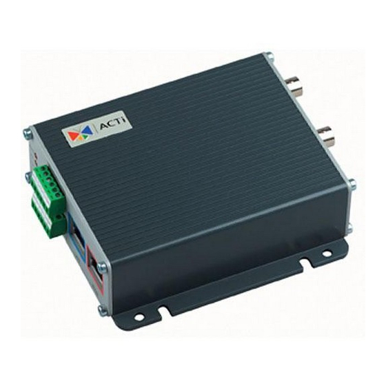
Page 10: Physical Description
1.5 Physical Description Video Input / Output The video server supports one analog video input and output of composite signal with BNC connectors Dip Switch for Serial Port RS-485 or RS-422 pin define (default is RS-485) RS-232 pin define Action LED Indicator The LED will light up after video server has successfully completed the boot process. - Page 11 the Reset Button depressed. While continuing to hold the reset button depressed, reconnect the power cable. Step 3: Keep holding the reset button depressed around 6 seconds, release the reset button. The unit will start up with factory default settings. Terminal Blocks Pin 1~6 The video server supports two alarm input and two alarm output.
- Page 12 Power Input (DC +12V) Ground Pin of Power Input & RS-232 LAN Port The Video server connects to the LAN (local area network) via a standard RJ45 connector. Supporting NWAY, this Video server can auto detect the speed of local network segment (10Base-T/100Base-TX Ethernet).
-
Page 13: Installation
INSTALLATION 2.1 Mounting the Video Server... -
Page 14: Basic Connections
2.2 Basic Connections Follow the procedures below to connect the video server to the respective apparatuses. 1. Connect an analog monitor to video server video out (BNC connector). 2-10... - Page 15 2. Connect the power adaptor to video server 3. Connect the video server’s LAN port to an Ethernet (RJ45 connectors) 4. Connect a PC to the Ethernet hub (RJ45 connectors) Note: software installation please refers to Software User Manual. 2-11...
Need help?
Do you have a question about the SED-2120 and is the answer not in the manual?
Questions and answers