Table of Contents
Advertisement
Advertisement
Table of Contents

Related Manuals for ACTi ACD-2100


Summary of Contents for ACTi ACD-2100
-
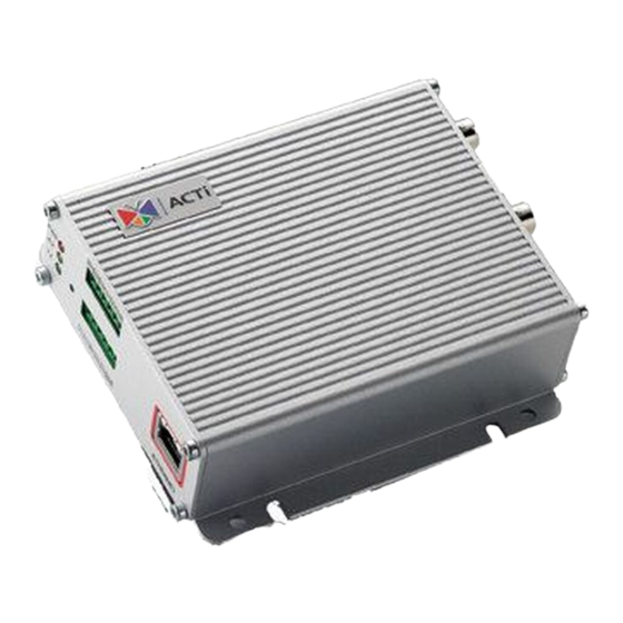
Page 1: Video Server
Video Server ACD-2100 Ver. 080619 User’s Manual... -
Page 2: Trademarks
PRECAUTIONS Read these instructions All the safety and operating instructions should be read before the product is operated. Heed all warnings All warnings on the product and in the instruction manual should be adhered to. The symbol indicates the following items, please carefully read the description next to each symbol. - Page 3 and can radiate radio frequency energy and, if not installed and used in accordance with the instruction manual, may cause harmful interference to radio communications. Operation of this equipment in a residential area is likely to cause harmful interference in which case the user will be required to correct the interference at his own expense.
-
Page 4: Table Of Contents
Table of Contents PRECAUTIONS....................0-1 Trademarks ..........................0-1 Liability............................0-1 FCC/CE Regulation ........................0-1 INTRODUCTION..................... 1-1 Package Contents ....................1-1 Features and Benefits..................1-2 Safety Instructions ....................1-4 Physical Description.................... 1-6 Mounting the Video Server ................1-9 Basic Connections ..................... 1-10 Product Specification..................1-11... -
Page 5: Introduction
INTRODUCTION 1.1 Package Contents ACD-2100 Warranty Card Software CD Terminal Blocks & Screws Power Adaptor (Option) -
Page 6: Features And Benefits
1.2 Features and Benefits This IP device is a cutting-edge digital video transmission device. It can compress and transmit real time images with outstanding images quality (D1, 720x480) at reasonable bandwidth through a standard TCP/IP network. That is because it is Ethernet ready and has the powerful ARM9 SoC and the MPEG-4 compression ASIC inside. - Page 7 to use. Users can easily utilize the existing PC to be a digital video recorder. Schedule recording and manual recording keep every important image recorded in the local hard disk. Reliable and accurate motion detection with instant warning makes you responsive in every condition. Quick and simple search and playback function lets you easily find the images you want.
-
Page 8: Safety Instructions
1.3 Safety Instructions Don’t use the power supply with other voltages This device is likely to be damaged or damage other equipments / personnel, if you use a power supply with different voltage than the one included with this device. All warranty of this product will be voided in the situations above. - Page 9 If the video product does not operate normally by following the operating Instructions in this manual. Adjust only those controls that are covered by the instruction manual as an improper adjustment . Other controls may result in damage and will often require extensive work by a qualified technician to restore the video product to its normal operation.
-
Page 10: Physical Description
1.4 Physical Description Video Input / Outpu The IP device supports one analog video input and output of composite signal with BNC connectors Audio Input / Output The IP device supports one audio input and output with earphone jack Dip Switch for Serial Port RS-485 or RS-422 pin define (default is RS-485) RS-232 pin define Action LED Indicator... - Page 11 Step 2: Using a suitable pointed object, press and continue to hold the Reset Button depressed. While continuing to hold the reset button depressed, reconnect the power cable. Step 3: Keep holding the reset button depressed around 6 seconds, release the reset button. The unit will start up with factory default settings.
- Page 12 Ground Pin of Power Input & RS-232 Ethernet Port The IP device connects to the Ethernet via a standard RJ45 connector. Supporting NWAY, this IP device can auto detect the speed of local network segment (10Base-T/100Base-TX Ethernet).
-
Page 13: Mounting The Video Server
1.5 Mounting the Video Server... -
Page 14: Basic Connections
1.6 Basic Connections Follow the procedures below to connect the IP device to the respective apparatuses. 1. Connect an analog monitor to IP device video out (BNC connector). 2. Connect the power adaptor to IP device 3. Connect IP device’s ethernet port to an Ethernet (RJ45 connectors).. 4. -
Page 15: Product Specification
1.7 Product Specification 1-11...
Need help?
Do you have a question about the ACD-2100 and is the answer not in the manual?
Questions and answers