Advertisement
Quick Links
Advertisement

Subscribe to Our Youtube Channel
Related Manuals for ACTi SED-2320Q


Summary of Contents for ACTi SED-2320Q
-
Page 1: Quick Installation Guide
4-CH Video Server SED-2320Q Ver. 061031 Quick Installation Guide... -
Page 2: Package Contents
INTRODUCTION 1.1 PACKAGE CONTENTS SED-2320Q Software CD Terminal Blocks & Screws Warranty Card Power Adaptor (Option) -
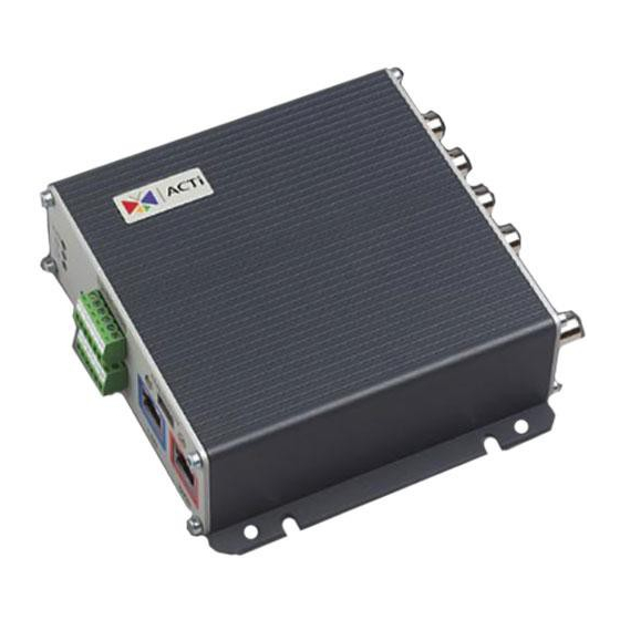
Page 3: Physical Description
PHYSICALDESCRIPTION Video Output The video server supports one analog video output of composite signal with BNC connector CAM1, CAM2, CAM3 and CAM4 Analog Video Input of Composite Signal with BNC Connectors. Audio Input / Output The video server supports one audio input and output with earphone jack Action LED Indicator The LED will light up after video server has successfully... - Page 4 release the reset button. The unit will start up with factory default settings. Terminal Blocks Pin 1~6 NAME DESCRIPTION Digital Output 1 Digital Output 2 Ground Pin Digital Input 1 Digital Input 2 Ground Pin Please find Support package” TS-00045” for details. Terminal Blocks Pin 7~12 DESCRIPTION NAME...
- Page 5 10. WAN Port The Video server connects to the WAN (wide area network) via a standard RJ45 connector. Supporting NWAY, this Video server can auto detect the speed of local network segment (10Base-T/100Base-TX Ethernet). The WAN port is for FTTH and can connect to a xDSL or cable modem.
- Page 6 1.3 CONNECT NECESSARY CABLES Follow the procedures below to connect the video server to the respective apparatuses. Please refer to page 1-6 for more details. Connect an analog video source (eg. CCD Camera) to the video server’s CAM1 ~ CAM4(BNC connector). Connect an analog monitor to the video server’s Monitor-Out (BNC connector) Connect the video server’s LAN port to an Ethernet hub (RJ45...
-
Page 7: Quick Tour
Quick Tour This section guides you with a quick tour on the 4-CH video server. 2.1 Configure the 4-CH Video Server 2.1.1 Make sure network environment Default IP of video server is 192.168.0.100. Please make sure the video server and your PC on the same network segment before running the installation. - Page 8 Open Internet Explorer with IP address This section describes how to configure the video server. The product administrator has unlimited access to all setup windows and normal users can only watch the live images. The video server is configured under a standard browser (Microsoft Internet Explorer 6.0 or above).
- Page 9 Once successfully login, the “Main Setup page” will be displayed as below.
- Page 10 Video Display STEP2: Check the [Mute] checkbox to select mute enable/disable STEP3: Click the [Audio Out] checkbox to enable/disable audio output from control PC to IP device. STEP3: Click to choose a display mode, such as quad video, or a single channel video.
- Page 11 2.1.4 Host Setting This section tells you how to setup video server’s host settings and LAN settings. STEP1: Click the [Host Setting] on the “Main Setup page”. The “Host setting page” is displayed as below. STEP2: Configure these settings with reference to the table below. If you are still unsure what to set, contact your system administrator.
- Page 12 Select the language of default user-interface. Each user login Language will see the default user-interface first. ■ LAN Setting Parameters Description The address shown is the current LAN port IP address of this IP device. You can change its IP address by change the parameter IP address here.
- Page 13 the application program (eg. IP utility). port1 Search server Select the port2 for this IP device to support search function of the application program (eg. IP utility). port2 STEP3: Click the [Apply] button of each setting to confirm the settings or click the [Reset] button to re-enter the parameters.
- Page 14 2.1.5 Video Setting This section tells you how to setup IP device’s video and streaming settings. STEP1: Click the [Video Setting] on the “Main Setup page”. The “Video setting page” is displayed as below STEP2: Select streaming protocol [Version V1.0] (without audio function) or [Version V2.0] (with audio function), and click [Setting] button to config settings, or [Reset] button to re-enter the...
- Page 15 ■ Video setting of Version V1.0 ■ Video setting of Version V1.0 Parameters Description The camera name is reserved for customer use. Camera name Select the streaming mode in the LAN. You can select TCP (TCP/IP) mode or Multicast mode to send video streaming.
- Page 16 Select the bit rate of the video streaming. You can select from 28Kbps to 3Mbps. Note: Lower bit rate consumes less bandwidth but Bitrate delivers lower quality images. High bit rate consumes more bandwidth but delivers higher quality images. Select the frame rate mode. Constant: The streaming’s frame rate remains constant at all conditions.
- Page 17 ■ Video setting of Version V2.0 STEP2: Configure these settings with reference to the table below. If you are still unsure what to set, contact your system administrator. ■ Video setting Parameters Description Select the streaming mode in the LAN. You can select TCP mode or Multicast mode to send video streaming.
- Page 18 Select video type connected to the video-in of this video server. If you use an incorrect video type, some images Analog video might be lost. Select the multicast TTL. Defualt setting is 255. Multicast TTL Select the video resolution of the video server. Resolution Select the bit rate of the video streaming.
- Page 19 NOTE: Once finished all settings, be sure to click the [Save Reboot] button, otherwise, some settings won’t take effect. Search Server Port1 & Search Server Port2, NOTE: If you change then you need to change ports in IP Utility when searching for this video server.
Need help?
Do you have a question about the SED-2320Q and is the answer not in the manual?
Questions and answers