Advertisement
Quick Links
1.
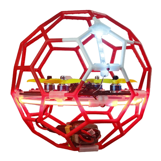
Bottom cover assembly
2. Frame installation
Flyball installation steps
Installation steps
6 through joints
connect to be
bottom half ball
As shown in the figure,
the battery panel and
A-B block are assembled
by
fixing
with
screws, and affixed with
four single-sided buffer
glue
(130GT
leftover
pieces).
M2*9
Advertisement

Related Manuals for LDARC FLYBALL 230


Summary of Contents for LDARC FLYBALL 230
- Page 1 Installation steps Bottom cover assembly 6 through joints connect to be bottom half ball As shown in the figure, the battery panel and A-B block are assembled fixing with M2*9 screws, and affixed with four single-sided buffer glue (130GT leftover pieces).
- Page 2 3. Soldering Flyball soldering Connect the two sections of 16# power cord, weld XT60, and set the heat shrinkable tube for heat sealing...
- Page 3 Divided 300mm red&black line into two parts and added tin at both ends. Tin added on 12V soldering joint Set the heat shrinkable tube to heat seal...
- Page 4 150mm red and black wire welding COB lamp belt Note: black ball with blue tape, red ball with red tape Welding of 1.4P LED hum assembly line and 3-color row line Add heat shrinkable tube separately after welding...
- Page 5 Cut off the 3P plug and solder it to the programming lamp Marking of welding points...
- Page 6 Cut the motor wire with remaining 55mm and tin; black crossing Silver sequential The power cord is soldered to the lower pad of the ESC, and the BEC 70mm wire is soldered to the upper pad of the ESC 4. Casing, LED installation Note: The notch of the tube seat faces to the arc center...
- Page 7 lamp penetrates through the notch of the tail tube seat, exits from the right side of the tube seat, then penetrates the Teflon tube, and sets it into the tube seat. Insert the tube into the left side of the tube seat...
- Page 8 5. Frame and protective installation Assemble the COB lamp set onto the bottom half ball Note: Avoid bending the lamp tube when adjusting the tube seat M2.9 round head screws Install the frame were used onto tube seats on the by fixing screws.
- Page 9 Use acetate tape to tie the light cord to the side arm Tie the power cord with a cable tie 6. Connecting with receiver Plug in the receiver cable and thread the plug to the bottom (for the receiver version, paste it on top of the flight controller, tie it with a cable tie, and paste the antenna on the end of...
- Page 10 7.Install the propeller correctly, pay attention to the direction of rotation of the propeller, and sort out the connecting lines so that the rotation of the propeller should not be affected. 8.The installation of protective cover on upper flyball 11 black pentagons and 1 red pentagon form the upper ball (if it is a red ball, then it is 11 red and 1...
- Page 11 9. Upper and lower protective cover, rear LED assembly Thread the rear light into a 70mm Teflon tube, and then assemble it to the rear light holder...
- Page 12 FPV UPGRATION 1. Installation of VTX (KKT20-V200) (replace the original fly Super_S F4 tower M2*25 screws with M2*30 screws), and use spacers and screws to assemble the VTX as shown in the figure below. KKT20-V200 2. Install the camera (RunCam nano 2) with M2*3.5 screws, and mark the flight control port connected in a red frame.
- Page 13 RECEIVER CONNECT 1. S.BUS and PPM receiver...
- Page 14 2. iBUS receiver 3. DSM2 and DSMX receiver...
- Page 15 BETAFLIGHT Please go to the Google App Store to download and install the BETAFLIGHT Assistant Software...
Need help?
Do you have a question about the FLYBALL 230 and is the answer not in the manual?
Questions and answers