baltur TBML 450LX ME Instruction Manual For Installation, Use And Maintenance
Electronic modulating mixed gas/diesel burner
Hide thumbs
Also See for TBML 450LX ME:
Table of Contents
Advertisement
Available languages
Available languages
Quick Links
ITALIANO
Manuale istruzioni per l'installazione, l'uso
e la manutenzione
Instruction manual for
installation, use and maintenance
ISTRUZIONI ORIGINALI (IT)
ORIGINAL INSTRUCTIONS (IT)
BRUCIATORE MISTO GAS/GASOLIO A MODULAZIONE ELET-
ELECTRONIC MODULATING MIXED GAS/DIESEL BURNER
IT
EN
TBML 450LX ME
TBML 510LX ME
TBML 650LX ME
TBML 750LX ME
0006160357_202106
TRONICA
Advertisement
Chapters
Table of Contents

Related Manuals for baltur TBML 450LX ME


Summary of Contents for baltur TBML 450LX ME
- Page 1 BRUCIATORE MISTO GAS/GASOLIO A MODULAZIONE ELET- TRONICA ELECTRONIC MODULATING MIXED GAS/DIESEL BURNER ITALIANO TBML 450LX ME Manuale istruzioni per l'installazione, l'uso e la manutenzione TBML 510LX ME Instruction manual for installation, use and maintenance TBML 650LX ME TBML 750LX ME...
-
Page 3: Table Of Contents
ITALIANO ITALIANO SOMMARIO Avvertenze per l'uso in condizioni di sicurezza ..............................2 Caratteristiche tecniche ......................................6 Materiale a corredo ......................................7 Dati registrazione prima accensione ................................7 Targa identificazione bruciatore..................................8 Campo di lavoro .......................................8 Caratteristiche costruttive ....................................9 Caratteristiche tecnico funzionali ..................................9 Descrizione componenti ....................................10 Dimensioni di ingombro .................................... -
Page 4: Avvertenze Per L'uso In Condizioni Di Sicurezza
ITALIANO AVVERTENZE PER L'USO IN CONDIZIONI DI • Il bruciatore NON deve essere utilizzato in cicli produttivi e processi industriali, disciplinati questi ultimi dallo Standard EN 746-2 SICUREZZA • La data di produzione dell'apparecchio (mese, anno) sono indicati sulla targa identificazione bruciatore presente sull'apparecchio. SCOPO DEL MANUALE •... - Page 5 • L’eventuale riparazione dei prodotti dovrà essere effettuata sola- - Tarare la portata di combustibile del bruciatore secondo la poten- mente da un centro di assistenza autorizzato da BALTUR o dal suo za richiesta dal generatore di calore. distributore locale, utilizzando esclusivamente ricambi originali.
- Page 6 ITALIANO AVVERTENZE PARTICOLARI PER L’USO DEL GAS. persone inesperte; • Verificare che la linea di adduzione e la rampa siano conformi alle - ll cavo di alimentazione dell’apparecchio non deve essere sosti- norme e prescrizioni vigenti. tuito dall’utente. In caso di danneggiamento del cavo, spegnere •...
- Page 7 ITALIANO A CURA DELL'INSTALLATORE - Si raccomanda che il dispositivo di arresto di emergenza sia di • Installare un idoneo sezionatore per ciascuna linea di alimentazione colore rosso e la superficie dietro di esso sia di colore giallo. del bruciatore. - L’azione di emergenza deve essere di tipo mantenuto e richiede- •...
-
Page 8: Caratteristiche Tecniche
ITALIANO CARATTERISTICHE TECNICHE MODELLO TBML 450LX ME TBML 510LX ME TBML 650LX ME TBML 750LX ME Potenza termica max metano 4700 5200 6500 7500 Potenza termica min metano mg/kWh ¹) emissioni metano Classe 3 Classe 3 Classe 3 Classe 3... -
Page 9: Materiale A Corredo
Emissioni NOx in mg/kWh gas propano ≤ 230 ≤ 180 ≤ 140 ≤ 110 MATERIALE A CORREDO MODELLO TBML 450LX ME TBML 510LX ME TBML 650LX ME TBML 750LX ME Guarnizione flangia attacco bruciatore Prigionieri N°4 - M20 N°4 - M20 N°4 - M20... -
Page 10: Targa Identificazione Bruciatore
ITALIANO TARGA IDENTIFICAZIONE BRUCIATORE Logo aziendale Ragione sociale azienda Codice prodotto Modello bruciatore Matricola Potenza combustibili liquidi Potenza combustibili gassosi Pressione combustibili gassosi Viscosità combustibili liquidi Potenza motore ventilatore Tensione di alimentazione Grado di protezione Paese di costruzione e numeri di certificato di omologazione Data di produzione mese / anno Codice a barre matricola bruciatore CAMPO DI LAVORO... -
Page 11: Caratteristiche Costruttive
ITALIANO CARATTERISTICHE COSTRUTTIVE CARATTERISTICHE TECNICO FUNZIONALI Il bruciatore risulta composto da: • Bruciatore misto in grado di funzionare alternativamente a gas natu- • Parte ventilante in lega leggera d'alluminio. rale oppure a gasolio (viscosità max 1.5° E a 20° C). •... -
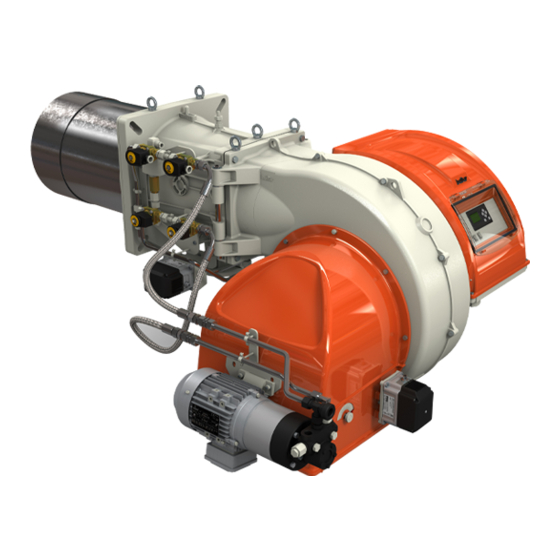
Page 12: Descrizione Componenti
ITALIANO DESCRIZIONE COMPONENTI Testa di combustione Guarnizione Flangia attacco bruciatore Valvola a farfalla modulazione erogazione gas Servomotore regolazione gas / gasolio Display apparecchiatura Pressostato aria Servomotore regolazione aria Quadro elettrico Cerniera Motore ventola Convogliatore aria in aspirazione Motore pompa Regolatore di portata combustibile liquido Elettrovalvola ritorno combustibile liquido Pressostato combustibile liquido Flangia attacco rampa gas... -
Page 13: Dimensioni Di Ingombro
ITALIANO DIMENSIONI DI INGOMBRO EØ FØ Modello TBML 450LX ME 1200 1850 547 ÷ 597 TBML 510LX ME 1200 1850 547 ÷ 597 TBML 650LX ME 1250 1850 547÷597 TBML 750LX ME 1330 1850 547÷597 Modello Ø E Ø F Ø... -
Page 14: Applicazione Del Bruciatore Alla Caldaia
CUFFIA FONICA nel caso sia richiesto di ridurre il livello di pressione sonora è neces- sario installare una cuffia fonica adeguata. (vedi tecnolistino contatta- re il rivenditore Baltur). 12 / 56 0006160357_202106... -
Page 15: Collegamenti Elettrici
ITALIANO COLLEGAMENTI ELETTRICI • Tutti i collegamenti devono essere eseguiti con filo elettrico flessi- bile. • Le sezioni dei conduttori non specificati sono da considerarsi di 0,75 mm². • Le linee elettriche devono essere distanziate dalle parti calde. • L’installazione del bruciatore è consentita solo in ambienti con grado di inquinamento 2 come indicato nella norma EN 60204-1. -
Page 16: Impianto Di Alimentazione Con Combustibile Liquido
Filtro combustibile liquido Valvola gas fiamma principale Servomotore regolazione gas / gasolio Pressostato gasolio di massima Dispositivo controllo tenuta valvole Regolatore di portata ritorno gasolio Limite fornitura baltur (integrato nell'apparecchiatura) e relativo A cura dell'installatore Elettrovalvole gasolio mandata pressostato Ritorno combustibile dall'ugello... -
Page 17: Pompa Ausiliaria
ITALIANO POMPA AUSILIARIA • Le tubazioni di collegamento devono essere dimensionate in funzio- ne della portata della pompa ausiliaria. In alcuni casi (eccessiva distanza o dislivello) è necessario effettuare • Evitare assolutamente il collegamento elettrico della pompa ausilia- l'impianto con un circuito di alimentazione ad "anello", con pompa au- ria direttamente al teleruttore del bruciatore. -
Page 18: Descrizione Del Funzionamento Con Combustibile Liquido
ITALIANO DESCRIZIONE DEL FUNZIONAMENTO CON COMBUSTIBILE LIQUIDO Il bruciatore è a funzionamento completamente automatico; chiuden- do l’interruttore generale e quello del quadro di comando il bruciatore viene inserito. Il funzionamento del bruciatore viene gestito dall'apparecchiatura elettronica di comando e controllo. La posizione di “blocco”... -
Page 19: Accensione E Regolazione Combustibile Liquido
ITALIANO ACCENSIONE E REGOLAZIONE COMBUSTIBILE LIQUIDO • Verificare che ci sia combustibile in cisterna. • Verificare che gli ugelli applicati sul bruciatore siano adatti alla po- tenzialità della caldaia e, se necessario, sostituirli con altri. • La quantità di combustibile erogata non deve essere superiore a quella massima richiesta dalla caldaia e a quella massima ammessa FUSE per il bruciatore. -
Page 20: Ugelli Fluidics Atomizer 12 N2 45
ITALIANO PRESSOSTATO GASOLIO SAUTER UGELLI FLUIDICS ATOMIZER 12 N2 45° Il bruciatore è dotato di un pressostato di sicurezza sul circuito di Per il funzionamento a gasolio impiegare ugelli FLUIDICS Atomizer ritorno del gasolio, il quale, montato in serie al pressostato aria ed 12 N2 45°. - Page 21 ITALIANO Entrata gasolio dal ritorno ugello. Valvola di intercettazione. Manometro con scala 0÷40 bar. Indice rotazione servomotore. Regolatore portata combustibile liquido. Uscita combustibile liquido verso il ritorno pompa. posizione 6:|s|regolatore di portata chiuso, portata massima erogata dall'ugello. posizione 0:|s|regolatore di portata completamente aperto, portata minima erogata dall'ugello.
-
Page 22: Descrizione Del Funzionamento Con Combustibile Gassoso
ITALIANO DESCRIZIONE DEL FUNZIONAMENTO CON camente provvede ad adeguare l'erogazione di combustibile e aria comburente inserendo i relativi servomotori. COMBUSTIBILE GASSOSO Il bruciatore riesce così ad ottimizzare la richiesta di calore da fornire alla caldaia. Il bruciatore è a funzionamento completamente automatico; chiuden- do l’interruttore generale e quello del quadro di comando il bruciatore viene inserito. -
Page 23: Accensione E Regolazione Gas Metano
ITALIANO ACCENSIONE E REGOLAZIONE GAS METANO • Portare l’interruttore (1), posto sul quadro di comando, nella posi- zione “O” (aperto). • Portare il selettore cambio combustibile nella posizione “GAS”. • Verificare che ci sia acqua in caldaia e che le saracinesche dell’im- pianto siano aperte. - Page 24 ITALIANO PERDITE IN TESTA LATO GAS TBML 450LX ME TBML 510LX • Durante la fase di definizione della curva di modulazione è possibile avere una stima approssimata della portata termica erogata nei pun- ti intermedi mediante la misura della pressione netta del gas nellla testa di combustione.
- Page 25 ITALIANO SENSORE FIAMMA La fotocellula è il dispositivo di controllo fiamma, e deve quindi essere in grado di intervenire se, durante il funzionamento, la fiamma si do- vesse spegnere (questo controllo deve essere effettuato dopo almeno un minuto dalla avvenuta accensione). Una leggera untuosità...
-
Page 26: Descrizione Del Funzionamento Pressostato Aria
ITALIANO DESCRIZIONE DEL FUNZIONAMENTO PRESSOSTATO ARIA Il pressostato aria ha lo scopo di mettere in sicurezza (blocco) l’appa- recchiatura se la pressione dell’aria non è quella prevista. Il pressostato deve quindi essere regolato per intervenire chiudendo il contatto NO (normalmente aperto) quando la pressione dell’aria nel bruciatore raggiunge il valore sufficiente. -
Page 27: Schema Di Regolazione Distanza Disco Elettrodi
ITALIANO SCHEMA DI REGOLAZIONE DISTANZA DISCO ELETTRODI TBML 450LX ME - TBML 510LX ME SCHEMA DI REGOLAZIONE TESTA DI COMBUSTIONE E DISTANZA DISCO ELETTRODI Flangia attacco bruciatore Aste con pomello per movimentazione diffu- Combustibile gassoso Combustibile liquido DEFAULT DEFAULT sore... -
Page 28: Schema Di Regolazione Distanza Disco Elettrodi
ITALIANO SCHEMA DI REGOLAZIONE DISTANZA DISCO ELETTRODI TBML 650LX ME - TBML 750LX ME SCHEMA DI REGOLAZIONE TESTA DI COMBUSTIONE E DISTANZA DISCO ELETTRODI Flangia attacco bruciatore Aste con pomello per movimentazione Combustibile gassoso Combustibile liquido DEFAULT DEFAULT diffusore Posizione (Z) Entrata combustibile gassoso TBML 650LX ME - 20 mm... -
Page 29: Precisazioni Sull'uso Del Propano
ITALIANO PRECISAZIONI SULL'USO DEL PROPANO • Valutazione, indicativa, del costo di esercizio; - 1 m3 di gas liquido in fase gassosa ha un potere calorifico infe- riore, di circa 25,6 kWh - Per ottenere 1 m3 di gas occorrono circa 2 Kg di gas liquido che corrispondono a circa 4 litri di gas liquido. -
Page 30: Schema Di Principio Per Riduzione Pressione G.p.l. A Due Stadi Per Bruciatore Oppure Caldaia
ITALIANO SCHEMA DI PRINCIPIO PER RIDUZIONE PRESSIONE G.P.L. A DUE STADI PER BRUCIATORE OPPURE CALDAIA Manometro e presa di pressione Riduttore di 1° salto Riduttore di 2° salto Uscita ~ 1,5 bar Uscita ~ 30 hPa (mbar) Portata ~ il doppio del massimo richiesto dall’utilizzatore Portata ~ il doppio del massimo richiesto dall’utilizzatore Giunto antivibrante Filtro... -
Page 31: Manutenzione
ITALIANO MANUTENZIONE Effettuare almeno una volta all’anno e comunque in conformità alle norme vigenti, l’analisi dei gas di scarico della combustione verifican- do la correttezza dei valori di emissioni. • Pulire le serrande aria, il pressostato aria con presa di pressione ed il relativo tubo se presenti. -
Page 32: Tempi Di Manutenzione
ITALIANO TEMPI DI MANUTENZIONE Descrizione particolare Azione da eseguire Gasolio TESTA DI COMBUSTIONE CONTROLLO VISIVO, INTEGRITA' CERAMICHE, SMERIGLIATURA ESTREMITA', VERIFICARE ELETTRODI ANNUO ANNUO DISTANZA, VERIFICARE CONNESSIONE ELETTRICA DISCO FIAMMA CONTROLLO VISIVO INTEGRITA' EVENTUALI DEFORMAZIONI, PULIZIA ANNUO ANNUO COMPONENTI TESTA COMBUSTIONE CONTROLLO VISIVO INTEGRITA' EVENTUALI DEFORMAZIONI, PULIZIA ANNUO ANNUO... -
Page 33: Vita Attesa
ITALIANO VITA ATTESA La vita attesa dei bruciatori e dei relativi componenti dipende molto dal tipo di applicazione su cui il bruciatore è installato, dai cicli, dalla potenza erogata, dalle condizioni dell’ambiente in cui si trova, dalla frequenza e modalità di manutenzione, ecc. ecc. Le normative relative ai componenti di sicurezza prevedono una vita attesa di progetto espressa in cicli e/o anni di funzionamento. -
Page 34: Istruzioni Per L'accertamento Delle Cause Di Irregolarità Nel Funzionamento E La Loro Eliminazione
ITALIANO ISTRUZIONI PER L'ACCERTAMENTO DELLE CAUSE DI IRREGOLARITÀ NEL FUNZIONAMENTO E LA LORO ELIMINAZIONE IRREGOLARITÁ POSSIBILE CAUSA RIMEDIO 1 Termostati (caldaia o ambiente) o presso- stati, aperti. 1 Alzare il valore dei termostati oppure attende- 2 Fotoresistenza in corto circuito. re che si chiudano i contatti per diminuzione 3 Mancanza di tensione in linea, interruttore naturale della temperatura o pressione. - Page 35 ITALIANO IRREGOLARITÁ POSSIBILE CAUSA RIMEDIO 1 Temperatura di esercizio della caldaia troppo bassa (inferiore al punto di rugia- 1 Aumentare la temperatura di esercizio. da). Corrosioni interne nella caldaia. 2 Aumentare la portata di gasolio se la caldaia 2 Temperatura dei fumi troppo bassa, lo consente.
- Page 36 ITALIANO IRREGOLARITÁ POSSIBILE CAUSA RIMEDIO 1 Regolare. 1 La pressione della pompa non è regolare. 2 Scaricare l'acqua dalla cisterna servendosi L’apparecchio va in blocco spruz- 2 Presenza di acqua nel combustibile. di una pompa adatta. Non usare mai per zando combustibile liquido senza il 3 Eccesso di aria comburente.
-
Page 37: Schemi Elettrici
ITALIANO SCHEMI ELETTRICI TBML 450 ME - 510 ME BT 335 35 / 56 0006160357_202106... - Page 38 ITALIANO TBML 450 ME - 510 ME BT 335 36 / 56 0006160357_202106...
- Page 39 ITALIANO TBML 450 ME - 510 ME BT 335 37 / 56 0006160357_202106...
- Page 40 ITALIANO TBML 450 ME - 510 ME BT 335 38 / 56 0006160357_202106...
- Page 41 ITALIANO TBML 450 ME - 510 ME BT 335 39 / 56 0006160357_202106...
- Page 42 ITALIANO TBML 650 ME - 750 ME BT 335 40 / 56 0006160357_202106...
- Page 43 ITALIANO TBML 650 ME - 750 ME BT 335 41 / 56 0006160357_202106...
- Page 44 ITALIANO TBML 650 ME - 750 ME BT 335 42 / 56 0006160357_202106...
- Page 45 ITALIANO TBML 650 ME - 750 ME BT 335 43 / 56 0006160357_202106...
- Page 46 ITALIANO TBML 650 ME - 750 ME BT 335 44 / 56 0006160357_202106...
- Page 47 ITALIANO APPARECCHIATURA Colore serie fili GNYE VERDE / GIALLO SENSORE FIAMMA SONDA DI PRESSIONE GRIGIO SONDA DI TEMPERATURA ACQUA BRUNO SONDA DI TEMPERATURA ESTERNA NERO SONDA ATTIVA CONNETTORE NERO CON SOVRASTAMPA RELE’ TERMICO RELE’ TERMICO POMPA GRUPPO POLVERIZZATORE FU1÷4 FUSIBILI SPIA BLOCCO ESTERNA / LAMPADA FUNZIONAMENTO RESI- STENZE AUSILIARIE SPIA DI FUNZIONAMENTO...
- Page 48 ITALIANO TBML 450 ME - 510 ME BT 340 46 / 56 0006160357_202106...
- Page 49 ITALIANO TBML 450 ME - 510 ME BT 340 47 / 56 0006160357_202106...
- Page 50 ITALIANO TBML 450 ME - 510 ME BT 340 48 / 56 0006160357_202106...
- Page 51 ITALIANO TBML 450 ME - 510 ME BT 340 49 / 56 0006160357_202106...
- Page 52 ITALIANO TBML 450 ME - 510 ME BT 340 50 / 56 0006160357_202106...
- Page 53 ITALIANO TBML 650 ME - 750 ME BT 340 51 / 56 0006160357_202106...
- Page 54 ITALIANO TBML 650 ME - 750 ME BT 340 52 / 56 0006160357_202106...
- Page 55 ITALIANO TBML 650 ME - 750 ME BT 340 53 / 56 0006160357_202106...
- Page 56 ITALIANO TBML 650 ME - 750 ME BT 340 54 / 56 0006160357_202106...
- Page 57 ITALIANO TBML 650 ME - 750 ME BT 340 55 / 56 0006160357_202106...
- Page 58 ITALIANO APPARECCHIATURA YS/YS1... ELETTROVALVOLA DI SICUREZZA APPARECCHIATURA PER DUE COMBUSTIBILI ELETTROVALVOLA DI SICUREZZA MANDATA SENSORE FIAMMA ELETTROVALVOLA DI SICUREZZA RITORNO SONDA ATTIVA Colore serie fili GNYE VERDE / GIALLO SONDA DI PRESSIONE SONDA DI TEMPERATURA GRIGIO SONDA DI TEMPERATURA ACQUA BRUNO SONDA DI TEMPERATURA ESTERNA NERO...
- Page 59 ENGLISH ENGLISH SUMMARY Warnings for use in safety conditions ..................................2 Technical specifications ......................................6 Standard accessories .......................................7 Data recorded during first start-up ..................................7 Burner identification plate ....................................8 Operating range .......................................8 Design characteristics ......................................9 Technical functional characteristics ..................................9 Component description ....................................10 Overall dimensions ......................................11 Burner connection to the boiler .....................................12 Electrical connections ......................................13 Liquid fuel supply system .....................................14...
-
Page 60: Warnings For Use In Safety Conditions
ENGLISH WARNINGS FOR USE IN SAFETY • The equipment use is allowed to such people only if they can have access to, through a responsible person, the information concerning CONDITIONS their safety, surveillance and instructions concerning equipment use. • Children must be watched over to prevent them from playing with PURPOSE OF THIS MANUAL the equipment. - Page 61 - At the end of the adjustment procedures, check that all the with it directly. Contact only qualified personnel. locking devices of mechanical securing systems are properly • Any product repairs must only be carried out by BALTUR authorised tightened. assistance centres or by its local distributor using only original spare - Make sure that the use and maintenance manual of the burner is parts.
- Page 62 ENGLISH SPECIAL PRECAUTIONS WHEN USING GAS. replace it contact qualified personnel only; • Check that the feed line and the train comply with current law and - If you decide not to use the equipment for a certain period of time regulations.
- Page 63 ENGLISH TO BE CARRIED OUT BY THE INSTALLER - The emergency activation device must be clearly visible and • Install a suitable disconnecting switch for each burner supply line. easily reachable and actionable in the immediate vicinity of the • The disconnection must be carried out by means of a device com- burner.
-
Page 64: Technical Specifications
ENGLISH TECHNICAL SPECIFICATIONS MODEL TBML 450LX ME TBML 510LX ME TBML 650LX ME TBML 750LX ME Maximum natural gas thermal power 4700 5200 6500 7500 Minimum natural gas thermal power mg/kWh ¹) natural gas emissions Class 3 Class 3 Class 3... -
Page 65: Standard Accessories
NOx emissions in mg/kWh propane gas ≤ 230 ≤ 180 ≤ 140 ≤ 110 STANDARD ACCESSORIES MODEL TBML 450LX ME TBML 510LX ME TBML 650LX ME TBML 750LX ME Burner coupling flange gasket Stud bolts N°4 - M20 N°4 - M20 N°4 - M20... -
Page 66: Burner Identification Plate
ENGLISH BURNER IDENTIFICATION PLATE Company logo Company name Product code Burner model Serial number Liquid fuel power Gaseous fuel power Gaseous fuel pressure Liquid fuel viscosity Fan motor power Power supply voltage Protection rating Country of origin and numbers of certificate of approval Manufacturing date - month / year Bar code serial number of burner OPERATING RANGE... -
Page 67: Design Characteristics
ENGLISH DESIGN CHARACTERISTICS TECHNICAL FUNCTIONAL CHARACTERISTICS The burner consists of: • Dual burner, able to operate alternately with natural gas or with die- • Ventilating part in light aluminium alloy. sel (max viscosity 1.5° E at 20°C). • Centrifugal fan for high performances. •... -
Page 68: Component Description
ENGLISH COMPONENT DESCRIPTION Combustion head Seal Burner connection flange Gas supply control butterfly valve Gas / diesel regulator servomotor Device display Air pressure switch Air regulation servomotor Electrical panel Hinge Fan motor Intake air conveyor Pump motor Liquid fuel flow rate regulator Liquid fuel return solenoid valve Liquid fuel pressure switch Gas train connector flange... -
Page 69: Overall Dimensions
ENGLISH OVERALL DIMENSIONS EØ FØ Model TBML 450LX ME 1200 1850 547 ÷ 597 TBML 510LX ME 1200 1850 547 ÷ 597 TBML 650LX ME 1250 1850 547÷597 TBML 750LX ME 1330 1850 547÷597 Model Ø E Ø F Ø L Ø... -
Page 70: Burner Connection To The Boiler
ENGLISH BURNER CONNECTION TO THE BOILER HEAD UNIT ASSEMBLY For the handling of the burner use a suitable and certified hoisting equipment to be anchored to the eyebolts as shown in the figure. Make sure that the combustion head penetrates into the furnace to the extent requested by the boiler manufacturer. -
Page 71: Electrical Connections
ENGLISH ELECTRICAL CONNECTIONS • It is advisable to make all connections with flexible electric wire. • Conductor cross-sections not specified are to be considered as 0,75 mm². • The power lines must be distanced from the hot parts. • The burner can be installed exclusively in environments with pollu- tion degree 2 as specified in Standard EN 60204-1. -
Page 72: Liquid Fuel Supply System
Valve seal control device (built-in the devi- Maximum diesel pressure switch ce) with relating pressure switch Diesel return flow rate regulator Limits on Baltur supply To be carried out by the installer Safety gas valve Diesel delivery solenoid valves Nozzle fuel return... -
Page 73: Auxiliary Pump
ENGLISH AUXILIARY PUMP • Avoid electrically connecting the auxiliary pump directly to the remo- te control switch of the burner. In some cases (excessive distance or differences in level) the system • Adjust the pressure at approx. 0.5 - 1 bar, if the circuit is equipped must be implemented with a "loop"... -
Page 74: Description Of Operation With Liquid Fuel
ENGLISH DESCRIPTION OF OPERATION WITH LIQUID FUEL The burner operates fully automatically: it is activated by switching on the main switch and the control panel switch. Burner operation is managed by command and control electronic de- vices. The “lock-out” position is a safety position that the burner automatical- ly assumes when a safety-related fault occurs. -
Page 75: Ignition And Adjustment With Liquid Fuel
ENGLISH IGNITION AND ADJUSTMENT WITH LIQUID FUEL • Make sure that there is fuel in the tank. • Check that the nozzles fitted on the burner are suitable for the boiler capacity. If necessary, replace them with suitable ones. • The quantity of fuel delivered must not exceed the maximum amount required by the boiler and the maximum amount allowed for the bur- FUSE ner. -
Page 76: Nozzles Fluidics Atomizer 12 N2 45
ENGLISH SAUTER DIESEL PRESSURE SWITCH NOZZLES FLUIDICS ATOMIZER 12 N2 45° The burner is equipped with a safety pressure switch on the diesel For diesel operation use nozzles FLUIDICS Atomizer 12 N2 45°. return circuit. It is installed in series to the air pressure switch and The diagrams represent the curves showing the values of the fuel is enabled only during diesel operation. - Page 77 ENGLISH Diesel inlet from nozzle return. Shut-off valve. Pressure gauge with 0÷40 bar scale. Servo motor rotation index. Liquid fuel flow rate adjustment. Liquid fuel output towards the pump return. position 6:|s|flow rate regulator closed, maximum flow rate delivered by the nozzle. position 0:|s|flow rate regulator completely open, minimum flow rate delivered by the nozzle.
-
Page 78: Operation Description With Gaseous Fuel
ENGLISH OPERATION DESCRIPTION WITH GASEOUS FUEL The burner operates fully automatically: it is activated by switching on the main switch and the control panel switch. Burner operation is managed by command and control electronic de- vices. Blown air burners with electronic modulation may be used on hearths under strong pressure or in a vacuum, according to the corresponding operating curves. -
Page 79: Natural Gas Ignition And Regulation
ENGLISH NATURAL GAS IGNITION AND REGULATION • Turn the switch (1) on the control panel to the “O” position (open). • Turn the fuel change-over switch to the “GAS” position. • Check that there is water in the boiler and that the gate valves of the system are open. - Page 80 ENGLISH HEAD LOSSES ON GAS SIDE TBML 450LX ME TBML 510LX ME • Upon defining the modulation curve, it is possible to have an ap- proximate estimate of the thermal flow rate delivered at the interme- diate points be measuring the gas pressure in the combustion head.
- Page 81 ENGLISH FLAME SENSOR The flame detecting UV photocell must be able to trigger upon system operation if the flame turns off (this check must be carried out after at least one minute from the ignition). Even the slightest greasiness will compromise the passage of rays through the photocell bulb, thus preventing the sensitive internal ele- ment from receiving the quantity of radiation necessary for it to work properly.
-
Page 82: Air Pressure Switch Functional Description
ENGLISH AIR PRESSURE SWITCH FUNCTIONAL DESCRIPTION The air pressure switch stops the equipment operation if air pressure is not at the expected value. The pressure switch must therefore be adjusted so that it is triggered to close the NO (normally open) contact when the air pressure in the burner reaches a particular value. -
Page 83: Diagram For Regulating The Electrode Disk Distance
ENGLISH DIAGRAM FOR REGULATING THE ELECTRODE DISK DISTANCE TBML 450LX ME - TBML 510LX ME DIAGRAM FOR REGULATING THE COMBUSTION HEAD AND THE ELECTRODE DISK DISTANCE Burner connection flange Rods with knob for diffuser handling Gaseous fuel Liquid fuel DEFAULT... -
Page 84: Diagram For Regulating The Electrode Disk Distance
ENGLISH DIAGRAM FOR REGULATING THE ELECTRODE DISK DISTANCE TBML 650LX ME - TBML 750LX ME DIAGRAM FOR REGULATING THE COMBUSTION HEAD AND THE ELECTRODE DISK DISTANCE Burner connection flange Rods with knob for diffuser handling Gaseous fuel Liquid fuel DEFAULT DEFAULT Gaseous fuel inlet Position (Z) -
Page 85: Specifications For Propane Use
ENGLISH SPECIFICATIONS FOR PROPANE USE • Operating costs approximate assessment; - 1 m3 of liquid gas in gaseous stage has a lower heating capacity, of nearly 25.6 kWh. - To obtain 1 cu.m of gas, about 2 kg of liquid gas are needed, i.e. about 4 litres of liquid gas. -
Page 86: Block Diagram Illustrating The Principle Of L.p.g. Pressure Reduction In Two Stages For Burner Or Boiler
ENGLISH BLOCK DIAGRAM ILLUSTRATING THE PRINCIPLE OF L.P.G. PRESSURE REDUCTION IN TWO STAGES FOR BURNER OR BOILER Pressure gauge and pressure intake 1st step reducer 2nd step reducer Output ~ 1.5 bar Output ~ 30 hPa (mbar) Flow rate ~ double the maximum required by the user Flow rate ~ double the maximum required by the user Vibration-proof joint Filter... -
Page 87: Maintenance
ENGLISH MAINTENANCE Analyse combustion gases and check that the emission values are correct at least once a year, in compliance with current law. • Clean air dampers, the air pressure switch with pressure port and the relevant pipe, if any. •... -
Page 88: Maintenance Time
ENGLISH MAINTENANCE TIME Part description Action to be performed Diesel COMBUSTION HEAD VISUAL INSPECTION OF THE INTEGRITY OF CERAMICS. TIP GRINDING, CHECK DISTANCE, ELECTRODES YEARLY YEARLY CHECK ELECTRICAL CONNECTION FLAME DISC INTEGRITY VISUAL CHECK FOR ANY DEFORMATIONS, CLEANING, YEARLY YEARLY COMBUSTION HEAD COMPONENTS INTEGRITY VISUAL CHECK FOR ANY DEFORMATIONS, CLEANING, YEARLY... -
Page 89: Expected Lifespan
ENGLISH EXPECTED LIFESPAN The expected lifespan of burners and relevant components depends very much from the type of application on which the burner is installed, from cycles ,of delivered power, from the conditions of the environment in which it is located, from maintenance frequency and mode, etc. Standards about safety components provide for a project expected lifespan expressed in cycles and/or years of operation. -
Page 90: Instructions For Determining The Cause Leading To Irregularities In The Operation And Their Elimination
ENGLISH INSTRUCTIONS FOR DETERMINING THE CAUSE LEADING TO IRREGULARITIES IN THE OPERATION AND THEIR ELIMINATION IRREGULARITY POSSIBLE CAUSE REMEDY 1 Thermostats (boiler or room) or pressure switches are open. 1 Raise the thermostats settings, or wait that 2 Photoresistor in short circuit. the contacts close for natural decrease of The burner does not start.(The 3 Absence of line voltage, main switch open,... - Page 91 ENGLISH IRREGULARITY POSSIBLE CAUSE REMEDY 1 Boiler operating temperature too low 1 Increase the operating temperature. (below the dew point). Corrosion inside the boiler. 2 Increase diesel flow rate is the boiler allows 2 Smoke temperature too low, approxima- tely below 130 °C for diesel. 1 Excessive cooling of smoke (approxi- mately below 130°C) in the chimney, for 1 Improve insulation and close any opening...
- Page 92 ENGLISH IRREGULARITY POSSIBLE CAUSE REMEDY 1 Adjust. 1 Pump pressure is not regular. 2 Drain water from the tank using a suitable 2 Water in the fuel. pump. Never use the burner pump for this The burner goes into lock-out 3 Too much combustion air.
-
Page 93: Wiring Diagrams
ENGLISH WIRING DIAGRAMS TBML 450 ME - 510 ME BT 335 35 / 56 0006160357_202106... - Page 94 ENGLISH TBML 450 ME - 510 ME BT 335 36 / 56 0006160357_202106...
- Page 95 ENGLISH TBML 450 ME - 510 ME BT 335 37 / 56 0006160357_202106...
- Page 96 ENGLISH TBML 450 ME - 510 ME BT 335 38 / 56 0006160357_202106...
- Page 97 ENGLISH TBML 450 ME - 510 ME BT 335 39 / 56 0006160357_202106...
- Page 98 ENGLISH TBML 650 ME - 750 ME BT 335 40 / 56 0006160357_202106...
- Page 99 ENGLISH TBML 650 ME - 750 ME BT 335 41 / 56 0006160357_202106...
- Page 100 ENGLISH TBML 650 ME - 750 ME BT 335 42 / 56 0006160357_202106...
- Page 101 ENGLISH TBML 650 ME - 750 ME BT 335 43 / 56 0006160357_202106...
- Page 102 ENGLISH TBML 650 ME - 750 ME BT 335 44 / 56 0006160357_202106...
- Page 103 ENGLISH CONTROL BOX Wire series colour GNYE GREEN / YELLOW Flame sensor BLUE PRESSURE PROBE GREY WATER TEMPERATURE PROBE BROWN EXTERNAL TEMPERATURE PROBE BLACK ACTIVE PROBE BLACK CONNECTOR WITH OVERPRINT THERMAL RELAY PUMP THERMAL RELAY SPRAY NOZZLE UNIT FU1÷4 FUSES EXTERNAL LOCK INDICATOR LIGHT/ AUXILIARY HEATING ELEMENT OPERATION LAMP OPERATION INDICATOR LIGHT...
- Page 104 ENGLISH TBML 450 ME - 510 ME BT 340 46 / 56 0006160357_202106...
- Page 105 ENGLISH TBML 450 ME - 510 ME BT 340 47 / 56 0006160357_202106...
- Page 106 ENGLISH TBML 450 ME - 510 ME BT 340 48 / 56 0006160357_202106...
- Page 107 ENGLISH TBML 450 ME - 510 ME BT 340 49 / 56 0006160357_202106...
- Page 108 ENGLISH TBML 450 ME - 510 ME BT 340 50 / 56 0006160357_202106...
- Page 109 ENGLISH TBML 650 ME - 750 ME BT 340 51 / 56 0006160357_202106...
- Page 110 ENGLISH TBML 650 ME - 750 ME BT 340 52 / 56 0006160357_202106...
- Page 111 ENGLISH TBML 650 ME - 750 ME BT 340 53 / 56 0006160357_202106...
- Page 112 ENGLISH TBML 650 ME - 750 ME BT 340 54 / 56 0006160357_202106...
- Page 113 ENGLISH TBML 650 ME - 750 ME BT 340 55 / 56 0006160357_202106...
- Page 114 ENGLISH CONTROL BOX YS/YS1... SAFETY SOLENOID VALVE DUAL FUEL EQUIPMENT DELIVERY SAFETY SOLENOID VALVE Flame sensor RETURN SAFETY SOLENOID VALVE ACTIVE PROBE Wire series colour GNYE GREEN / YELLOW PRESSURE PROBE BLUE TEMPERATURE PROBE GREY WATER TEMPERATURE PROBE BROWN EXTERNAL TEMPERATURE PROBE BLACK THERMAL RELAY BLACK CONNECTOR WITH OVERPRINT...
- Page 116 BALTUR S.P.A. Via Ferrarese, 10 44042 Cento (Fe) - Italy Tel. +39 051-6843711 Fax. +39 051-6857527/28 www.baltur.it info@baltur.it Il presente catalogo riveste carattere puramente indicativo. La casa, pertanto, si riserva ogni possibilità di modifica dei dati tecnici e di quant'altro in esso riportato.
Need help?
Do you have a question about the TBML 450LX ME and is the answer not in the manual?
Questions and answers