Fanvil PA2S User Manual
Hide thumbs
Also See for PA2S:
- How-to (6 pages) ,
- Quick installation manual (6 pages) ,
- User manual (57 pages)
Table of Contents
Advertisement
Quick Links
Advertisement
Table of Contents

Subscribe to Our Youtube Channel
Related Manuals for Fanvil PA2S


Summary of Contents for Fanvil PA2S
- Page 1 PA2S User Manual Software Version: 1.0.0 Release Date:2021/1/8 1...
-
Page 2: Table Of Contents
Directory Directory................................2 1 Picture................................4 2 Table.................................. 6 3 Safety Instruction............................7 4 Overview................................8 5 Install Guide..............................9 5.1 Use POE or external Power Adapter....................9 5.2 Appendix..............................9 5.2.1 Common command modes.......................9 5.2.2 Function key LED status......................10 6 User Guide...............................11 6.1 Interface description.......................... - Page 3 9.5 System >> Upgrade.......................... 27 9.6 System >> Auto Provision........................29 9.7 System >> FDMS..........................32 9.8 System >> Tools..........................33 9.9 Network >> Basic..........................33 9.10 Network >> service port......................... 35 9.11 VPN..............................36 9.12 Network >> Advanced........................38 9.13 LINES >> SIP........................... 39 9.14 Line >>...
-
Page 4: Picture
Picture Picture 1 - Interface display ..............11 Picture 2 - WEB Login........................14 Picture 3 - SIP Line Configuration ....................15 Picture 4 - Volume Set...........................15 Picture 5 - Speaker..........................16 Picture 6 - Function Setting........................17 Picture 7 - WEB line enable auto answer...................18 Picture 8 - Enable auto answer for IP calls................... - Page 5 Picture 37 - Function Key........................60 Picture 38 - Memory Key........................62 Picture 39 - Multicast .......................... 63 Picture 40 - Advanced Setting......................64 Picture 41 - WEB filter........................64 Picture 42 - Trust Certificates......................65 Picture 43 - Device Certificates......................66 Picture 44 - Firewall........................... 66 Picture 45 - Firewall rules list.......................
-
Page 6: Table
Table Table 1 - Common command mode....................9 Table 2 - Function key LED status......................10 Table 3 - Interface Description......................11 Table 4 - Configuration instructions....................13 Table 5 - Power Supply......................... 16 Table 6 - Intercom..........................21 Table 7 - MCAST..........................22 Table 8 - SIP Hotspot......................... -
Page 7: Safety Instruction
Safety Instruction Please read the following safety notices before installing or using this unit. They are crucial for the safe and reliable operation of the device. Please use the external power supply that is included in the package. Other power supply ... -
Page 8: Overview
Overview PA2S is a SIP audio&video intercom and Public Announcement system device for industry application. The media stream transmission adopts standard IP/RTP/RTSP protocols. It has various functions and interfaces, such as Intercom, video, broadcast, recording and short circuit trigger, to adapt different application environments. Users can DIY the paging device... -
Page 9: Install Guide
For users who do not have POE equipment, the traditional power adaptor should be used. If the device is connected to both POE switch and external power adapter, PA2S will get power supply from POE switch in priority, and change to external power adapter once the POE power supply fails. -
Page 10: Function Key Led Status
5.2.2 Function key LED status Table 2- Function key LED status Type status SIP/NET Normally on Successfully Registered Fast Flashing Registration failed/network abnormality Slow Flashing In call... -
Page 11: User Guide
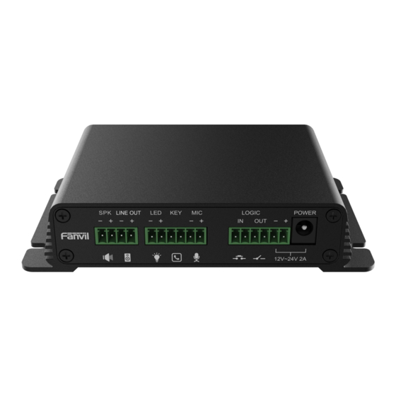
User Guide 6.1 Interface description Picture 1- Interface display Table 3- Interface Description Number Name Description Speaker port: according to the device input voltage adaptive output maximum power. 4Ω spkaker, POE/10W, 12V/10W, 18V/20W, 24V/30W. Speaker port The greater the horn impedance, the smaller the output power. - Page 12 port & line in be configured as audio line input function through software. port a)Sensitivity: -38dB, bias voltage 2.2V. b)Microphone signal cable it is recommended to use a shielded cable and connect the shield cable to the grounding screw, improve anti-interference. Switch input the connection switch, you need to log on to the relevant port...
-
Page 13: Installation Instructions
6.2 Installation instructions 6.2.1 Installation The first step: the device with metal strips (user-owned) fixed in the installation location. The second step: connect the function key, speaker, microphone and other peripheral devices to the corresponding port. (metal shell with thick wires connected to the device grounding screw.) The third step: plug the network cable and power, the device light flashes on behalf of the power connection is normal. -
Page 14: Web Configuration
6.3 WEB configuration When the device and your computer are successfully connected to the network, enter the IP address of the device on the browser as http://xxx.xxx.xxx.xxx/ and you can see the login interface of the web page management. Picture 2 - WEB Login The username and password should be correct to log in to the web page. -
Page 15: Volume Setting
Picture 3 - SIP Line Configuration 6.5 Volume setting Set the volume (if the speaker or microphone is not connected, you can skip it) [Phone Settings] >> [Media Settings] >> [Media Settings], as shown below, click [Submit]. Hands-free volume setting: Set the speaker output volume. Hands-free microphone gain: microphone volume level. -
Page 16: Set The Player Type
6.6 Set the player type Set the player type (the default is panel speaker mode) [Phone Settings] >> [Media Settings] >> [Media Settings] The system defaults to the <panel speaker> mode, which is an intercom panel terminal with a shell. In order to ensure the voice effect of hands-free intercom and avoid damage to the speaker, When speaking, the output power is limited to less than 10W. -
Page 17: Basic Function
Basic Function 7.1 Making Calls After setting the function key to Speed dial and setting the number, press the function key to immediately call out the set number, as shown below: Picture 6- Function Setting See detailed configuration instructions 9.26 Function Key 7.2 Answering Calls After setting up the automatic answer and setting up the automatic answer time, it will hear the ringing bell within the set time and automatically answer the call after timeout. - Page 18 the ring tone will be heard after the shutdown, and the auto-answer will not time out. Web interface: Enter [Line] >> [SIP], Enable auto answer and set auto answer time and click submit. Picture 7 - WEB line enable auto answer SIP P2P auto answering:...
-
Page 19: Call Waiting
is set. 7.5 Call Waiting Enable call waiting: new calls can be accepted during a call. Disable call waiting: new calls will be automatically rejected and a busy signal will be prompted Enable call waiting tone: when you receive a new call on the line, the device will beep. ... - Page 20 Picture 10 - Call Waiting tone...
-
Page 21: Advance Function
Enable Intercom the SIP header call-info of the Call request Command automatic call If the option is enabled, PA2S will answer the intercom call Enable Intercom Barge automatically while it is in a normal call, and it will reject new... - Page 22 Time Transport Protocol (RTP) stream to the pre-configured multicast address without involving SIP signaling. You can also configure the phone to receive an RTP stream from pre-configured multicast listening address without involving SIP signaling. You can specify up to 10 multicast listening addresses.
-
Page 23: Hotspot
the multicast address, and select the codec. Click Apply. Set up the name, host and port of the receiving multicast on the web page of [Phone Settings] >> [MCAST]. Press the DSSKey of Multicast Key which you set. ... - Page 24 SIP line Client Settings: As a SIP hotspot client, there is no need to set up a SIP account, which is automatically acquired and configured when the device is enabled. Just change the mode to "client" and the other options are set in the same way as the hotspot. Picture 13 - SIP hotspot The device is the hotspot server, and the default extension is 0.
-
Page 25: Web Configurations
Web Configurations 9.1 Web Page Authentication Users can log into the device's web page to manage user device information and operate the device. Users must provide the correct user name and password to log in. If the password is entered incorrectly three times, it will be locked and can be entered again after 5 minutes. The details are as follows: If an IP is logged in more than the specified number of times with a different user name, it ... -
Page 26: System >> Account
9.3 System >> Account Picture 14- WEB Account On this page the user can change the password for the login page. Users with administrator rights can also add or delete users, manage users, and set permissions and passwords for new users System >>... -
Page 27: System >> Upgrade
Export Configurations Right click to select target save as, that is, to download the device's configuration file, suffix “.txt”. (note: profile export requires administrator privileges) Import Configurations Import the configuration file of Settings. The device will restart automatically after successful import, and the configuration will take effect after restart Clear Configurations ... - Page 28 webpage. After the upgrade, the device will automatically restart and update to the new version. Click select, select the version and then click upgrade. Upgrade the ringtone,support wav and MP3 format. Firmware Upgrade: Web page: Login phone web page, go to [System] >> [Upgrade]. ...
-
Page 29: System >> Auto Provision
and upgrade button will become available; Click [Upgrade] button to upgrade the new firmware. When there is a corresponding TXT file and version on New version description the server side, the TXT and version information will be information displayed under the new version description information. The file requested from the server is a TXT file called vendor_model_hw10.txt.Hw followed ... - Page 30 Picture 18- Auto provision settings Devices support SIP PnP, DHCP options, Static provision, TR069. If all of the 4 methods are enabled, the priority from high to low as below: PNP>DHCP>TR069> Static Provisioning Transferring protocol: FTP、 TFTP、 HTTP、 HTTPS Table 10- Auto Provision Auto provision Parameters Description...
- Page 31 Username for configuration server. Used for FTP/HTTP/HTTPS. Authentication Name If this is blank the phone will use anonymous Authentication Password for configuration server. Used for FTP/HTTP/HTTPS. Password Configuration File Encryption key for the configuration file Encryption Key General Configuration File Encryption key for common configuration file Encryption Key Download Fail Check...
-
Page 32: System >> Fdms
phone will check the update every 1 hour. Provision Mode. 1. Disabled. Update Mode 2. Update after reboot. 3. Update after interval. TR069 Enable TR069 Enable TR069 after selection Enable TR069 If TR069 is enabled, there will be a prompt tone when connecting. Warning Tone ACS Server Type There are 2 options Serve type, common and CTC. -
Page 33: System >> Tools
Building a movie theater Name of equipment installation building room number Equipment installation room name 9.8 System >> Tools This page gives the user the tools to solve the problem. Picture 20 - Tools Syslog:When enabled, set the syslog software address, and log information of the device will be recorded in the syslog software during operation. - Page 34 Picture 21 - Network Basic Setting Table 12 - Network Basic Setting Field Explanation Name Network Status The current IP address of the equipment Subnet The current Subnet Mask mask Default The current Gateway IP address gateway The MAC address of the equipment MAC Time Display the time when the device gets the MAC address stamp...
-
Page 35: Network >> Service Port
If Static IP is chosen, the screen below will appear. Enter values provided by the ISP. DNS Server Configured Select the Configured mode of the DNS Server. Primary DNS Enter the server address of the Primary DNS. Server Secondary Enter the server address of the Secondary DNS. DNS Server attention:... -
Page 36: Vpn
Table 13- Server Port parameter description Web server type Restart after setting takes effect. Optional web login as HTTP/HTTPS Web login timeout The default is 15 minutes, the timeout will automatically log out of the login page, and you need to log in again Web page automatic No need to enter the user name and password after the timeout, login... - Page 37 Virtual Private Network (VPN) is a technology to allow device to create a tunneling connection to a server and becomes part of the server’s network. The network transmission of the device may be routed through the VPN server. For some users, especially enterprise users, a VPN connection might be required to be established before activate a line registration.
-
Page 38: Network >> Advanced
User then upload these files to the device in the web page [Network] -> [VPN], Section OpenVPN Files. Then user should check “Enable VPN” and select “OpenVPN” in VPN Mode and click “Apply” to enable OpenVPN connection. Same as L2TP connection, the connection will be established every time when system rebooted until user disable it manually. -
Page 39: Lines >> Sip
Enable Learning Function Learn the discovered device information on the device QoS Settings Pattern Voice quality assurance (off by default) DHCP VLAN Settings parameters values 128-254,Obtain the VLAN value through DHCP WAN port virtual Wan WAN port virtual Wan WAN port Settings LAN port virtual LAN LAN port virtual LAN port Settings... - Page 41 Picture 25- SIP Table 15 - SIP Parameters Description Register Settings Line Status Display the current line status at page loading. To get the up to date line status, user has to refresh the page manually. Server Address Enter the IP or FQDN address of the SIP server Server Port Enter the SIP server port, default is 5060 Authentication User...
- Page 42 the next field Call Forward Number for Unconditional Set the number of unconditional call forward Call Forward on Busy Enable call forward on busy, when the phone is busy, any incoming call will be forwarded to the number specified in the next field Call Forward Number for Busy Set the number of call forward on busy Call Forward on No Answer...
- Page 43 DTMF Type Set the DTMF type to be used for the line DTMF SIP INFO Mode Set the SIP INFO mode to send ‘*’ and ‘#’ or ‘10’ and ‘11’ Enable DND Enable Do-not-disturb, any incoming call to this line will be rejected automatically Registration Expiration Set the SIP expiration interval Use VPN...
- Page 44 Enable Session Timer Set the line to enable call ending by session timer refreshment. The call session will be ended if there is not new session timer event update received after the timeout period Session Timeout Set the session timer timeout period Enable BLF List Enable/Disable BLF List BLF List Number...
-
Page 45: Line >> Sip Hotspot
via field. Convert URI Convert not digit and alphabet characters to %hh hex code Use Quote in Display Name Whether to add quote in display name Enable GRUU Support Globally Routable User-Agent URI (GRUU) Sync Clock Time Time Sycn with server Caller ID Header Set the Caller ID Header Use 182 Response for Call waiting... - Page 46 Picture 26- Basic Settings Picture 27 - Line Basic Setting Table 16- Line Basic Setting Parameters Description STUN Settings Server Address Set the STUN server address Server Port Set the STUN server port, default is 3478 Binding Period Set the STUN binding period which can be used to keep the NAT pinhole opened.
-
Page 47: Intercom Settings >> Features
Auto Answering Automatic answer timeout setting Delay DTMF Type Set the DTMF type of the line. DTMF SIP INFO Set SIP INFO mode to send ‘*’ and ‘#’ or ‘10’ and ‘11’ Mode 9.16 Phone settings >> Features Picture 28 - Feature Table 17- Common device function Settings on the web page Parameters Description... - Page 48 can use the volume keys and mute key to unmute. Disable Mute for Ring When it is enabled,you can not mute the phone. If you select Ban Outgoing to enable it, and you cannot dial out any Ban Outgoing number. Enable Restricted Whether enable Restricted Incoming List Incoming List...
-
Page 49: Intercom Settings >> Media
answer the call after specific delay. Enable Intercom Mute Enable mute mode during the intercom call Enable Intercom Tone If the incoming call is intercom call, the phone plays the intercom tone Enable Intercom Barge Enable Intercom Barge by selecting it, the phone auto answers the intercom call during a call. -
Page 50: Intercom Settings>>Camera Settings
was not configured with specific ring type, the default ring will be used. Speakerphone Volume Set the speakerphone volume, the value must be 1~9 Speakerphone Ring Volume Set the ring volume in the speakerphone, the value must be 1~9 DTMF Payload Type Enter the DTMF payload type, the value must be 96~127. - Page 51 Picture 30- Camera Settings Table 19- Camera Settings Parameters Description camera settings Auto mode:The camera automatically makes the most appropriate adjustments according to the color temperature of the shooting scene, and automatically compensates for the color of the light source.。 Lock mode:Fixed white balance parameters will not be automatically adjusted according to the actual color temperature.
- Page 52 Manual exposure time :Set the exposure time by yourself, the range is 0~10000 Manual exposure gain:Set the exposure gain by yourself, the range is 0~1024 All manual :Manually set the exposure time and gain. It refers to the time to press the shutter. Increasing the exposure time can increase the signal-to-noise ratio and make the image clear.
- Page 53 Call Stream Main stream or sub stream used in video call Enable Onvif Is authentication required when using onvif protocol (with username and Auth password) When using rtsp protocol, whether authentication is required (with username Enable Rtsp Auth and password) H.264 Payload Set the load type of h.264, the range is 96~127 Type...
-
Page 54: Intercom Setting >> Mcast
Picture 31 - Snapshot Capture trigger mode: call state trigger Call status trigger: save the screenshot to the local / server when the status of outgoing call, incoming call and call is triggered. Snapshot save path: local (SD card / USB flash disk) Server address (supports uploading via FTP / TFTP / HTTP / HTTPS) ftp://IP : Port @ user name: password / path 9.19 Phone Setting >>... -
Page 55: Intercom Setting >> Time/Date
Picture 32- Action URL Note! The operation URL is used by the IPPBX system to submit device events. 9.21 Phone Setting >> Time/Date Users can configure the device's time Settings on this page. - Page 56 Picture 33 - Time/Date Table 21- Time/Date Time/Date Explanation Field Name Network Time Server Settings Time Synchronized via SNTP Enable time-sync through SNTP protocol Time Synchronized via DHCP Enable time-sync through DHCP protocol Primary Time Server Set primary time server address Set secondary time server address, when primary server is not Secondary Time Server reachable, the device will try to connect to secondary time server to...
-
Page 57: Intercom Settings>>Time Plan
Hour Start The DST start hour Month End The DST end month Week End The DST end week Weekday End The DST end weekday Hour End The DST end hour Manual Time Settings To set the time manually, you need to disable the SNTP service first, and you need to fill in and submit each item of year, month, day, hour and minute in the figure above to make the manual settings successful. -
Page 58: Intercom Settings >> Tone
U disk: select the audio file under the U disk SD card: select the audio file under the SD card Audio settings Select the audio file you want to play, it supports trial listening, and you can play it immediately after clicking the trial listening Repeat cycle Do not repeat: execute once within the set time range Daily: Perform this operation in the same time frame every day... -
Page 59: Call List >> Web Dial
User can add specific number to be blocked, or a prefix where any numbers matched the prefix will all be blocked. Restrict Outgoing Call You can set the rule to restrict some numbers from dialing out,until you remove the number from the table. -
Page 60: Function Key
9.26Function key Picture 37- Function Key Table 23- Function Key Parameters Description Function key settings Speed Dial:The user can directly dial the set number. This feature is memory convenient for customers to dial frequent numbers. Intercom: This feature allows the operator or secretary to quickly connect to the phone, widely used in office environments Key event The user can select a function key as a shortcut to trigger an event for... - Page 61 DTMF Press during a call to send the set DTMF Mcast Paging Configure the multicast address and voice encoding. User can initiate multicast by pressing this key Action URL The user can use a specific URL to make basic calls to the device, open the door, etc.
- Page 62 mode, see 5.2.1 Common Command Mode for details Advanced Settings Number 1 call number 2 mode selection. <Main/Secondary>: If the first number is not answered within the set time, Hot Key Dial Mode the second number will be automatically switched. Select <Day/Night>:The system time is automatically detected during the call.
- Page 63 called automatically answered. party Multicast Multicast function is to deliver voice streams to configured multicast address; all equipment monitored the multicast address can receive and play the broadcasting. Using multicast functionality would make deliver voice one to multiple which are in the multicast group simply and conveniently.
-
Page 64: Security >> Web Filter
Picture 40 - Advanced Setting 9.27Security >> Web filter Users can set up to allow only a certain network segment IP to access the device Picture 41- WEB filter Add and delete the allowed IP network segments; configure the start IP address in the start IP, configure the end IP address in the end IP, and then click [Add] to add successfully. -
Page 65: Security >> Trust Certificates
Note: If the device you access to the device is on the same network segment as the device, do not configure the web filtering network segment to be outside your own network segment, otherwise you will not be able to log in to the web page. 9.28Security >>... -
Page 66: Security >> Firewall
Picture 43- Device Certificates 9.30Security >> Firewall Picture 44 - Firewall Through this page, you can set whether to enable the input and output firewalls, and at the same time, you can set the input and output rules of the firewall. Use these settings to prevent malicious network access, or restrict internal users from accessing some resources of the external network, and improve safety. - Page 67 The firewall rule setting is a simple firewall module. This function supports two kinds of rules: input rules and output rules. Each rule will be assigned a serial number, and a maximum of 10 each rule can be set. Taking into account the complexity of firewall settings, the following will illustrate with an example: Table 26- Web Firewall parameter...
-
Page 68: Device Log
192.168.1.118 because of the prohibition of the output rule. But ping other IPs in the 192.168.1.0 network segment can still receive the response packets from the destination host normally. Picture 46- Delete firewall rules Select the list you want to delete and click [Delete] to delete the selected list. 9.31Device log You can crawl the device log, when you encounter unusual problems, please send the device log to the technical staff for positioning problem.For more detail... - Page 69 Security settings Parameters Description Basic settings Ringtone The Alarm ring duration Duration Input & Tamper Configure remote response server address (including remote response Server Address server address and trigger alarm server address) When the input port is triggered, a short message will be sent to the server. Message The message format is as follows:Alarm_Info:Description=$model;SIP User=$active_user;Mac=$mac;IP=$ip;port=$trigger...
-
Page 70: Trouble Shooting
10 Trouble Shooting When the device is not working properly, users can try the following methods to restore the device to normal operation or collect relevant information to send a problem report to the technical support mailbox. 10.1 Get device system information Users can obtain information through the [System] >>... -
Page 71: Get Device Log
10.5Get device log Log information is helpful when encountering abnormal problems. In order to obtain the log information of the device, the user can log on to the device web page, open the web page [device log], click the "start" button, follow the steps of the problem until the problem appears, and then click the "end"...
Need help?
Do you have a question about the PA2S and is the answer not in the manual?
Questions and answers