Table of Contents
Advertisement
Quick Links
Advertisement
Table of Contents

Related Manuals for Fanvil PA2


Summary of Contents for Fanvil PA2
- Page 1 User Manual Software Version: 2.6.0 Release Date:2019/09/20...
-
Page 2: Table Of Contents
Directory Directory ............................1 1 Picture ............................3 2 Table .............................. 5 3 Safety Instruction ......................... 1 4 Overview ............................2 5 Install Guide ....................错误!未定义书签。 5.1 Use POE or external Power Adapter ................3 5.2 Install ..........................4 5.2.1 button instruction ..................... 4 5.2.2 Confirm the connection .................... - Page 3 9.6 System >> Auto Provision ..................20 9.7 System >> FDMS ......................23 9.8 System >> Tools ......................23 9.9 Network >> Basic ......................24 9.10 Network >> Advanced ....................26 9.11 Network >> VPN ......................27 9.12 Network >> Web Filter ....................28 9.13 Line >>...
-
Page 4: Picture
1 Picture Picture 1 - button instruction ..................4 Picture 2 - connected graphs ..................6 Picture 3 - Quickly setting ....................8 Picture 4 - WEB Login ....................9 Picture 5 - SIP Line Configuration ................9 Picture 6 - Function Setting ..................10 Picture 7 - - Function Setting .................. - Page 5 Picture 37 - Trusted Certificates ................... 43 Picture 38 - Alert/Security Settings ................44 Picture 39 - Function Key Settings ................46 Picture 40 - Hot Key Settings ..................47 Picture 41 - Multicast Settings ..................47 Picture 42 - Advanced Settings ................. 48...
-
Page 6: Table
2 Table Table 1 - button instruction .................... 4 Table 2 - Common command mode ................6 Table 3 - Function key LED state ................... 6 Table 4 - Intercom ......................14 Table 5 - MCAST ......................15 Table 6 - SIP Hotspot ....................16 Table 7 - Auto provision .................... -
Page 7: Safety Instruction
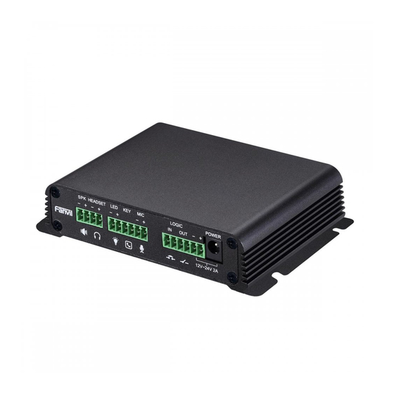
3 Safety Instruction Please read the following safety notices before installing or using this unit. They are crucial for the safe and reliable operation of the device. ⚫ Please use the external power supply that is included in the package. Other power supply may cause damage to the phone and affect the behavior or induce noise. -
Page 8: Overview
4 Overview PA2 is a SIP audio and video intercom developed specifically for the needs of industry users. Media streaming adopts the standard IP/RTP/RTSP protocol. It inherits the advantages of good stability of azimuthphone and carrier-grade sound quality, and is perfectly compatible with all current mainstream sip-based IPPBX/ soft switch /IMS platforms, such as Asterisk, Broadsoft, Metaswitch, 3CX, Elastix, etc. -
Page 9: Use Poe Or External Power Adapter
For users who do not have POE equipment, the traditional power adaptor should be used. If the device is connected to both PoE switch and external power adapter, PA2 will get power supply from PoE switch in priority, and change to external power adapter once the PoE power supply fails. -
Page 10: Install
5.2 Install Before you start using the device, please install the following: 5.2.1 button instruction Picture 1 - button instruction The image above shows the key layout of the device. Each button provides its own specific function. The user can refer to the instructions for the keys in the illustration in this section to operate the device. Table 1 - button instruction Label Explanation... -
Page 11: Confirm The Connection
When PA2’s external part is connected to metal shell or panel, please connect the ⑮Grounding screw external part to this interface, in order to prevent static electricity or other interferences which may affect the device’s normal working. -
Page 12: Appendix Table
Picture 2 - connected graphs 5.3 Appendix Table 5.3.1 Common command mode Table 2 - Common command mode Action Description Wait for captain to press volume down button 3s to report IP Standby to IP In standby mode, long press the volume button for 10 seconds, and there will be a beep sound and the indicator light will flash for 5 seconds. - Page 13 Type State Line/network Quick flashing Registration failed/ network abnormal Normally on Successfully registered Slow flashing In call...
-
Page 14: Basic Introduction
IP address of the device or use the "IP scan tool" software to find the IP address of the device.(Download http://download.fanvil.com/tool/iDoorPhoneNetworkScanner.exe) ◼ Long press the volume up button for 10 seconds (30 seconds after power on), wait for the speaker to emit rapid beep sound, then quickly press the volume up button for three times, the beep stops. -
Page 15: Sip Configurations
Picture 4 - WEB Login The username and password should be correct to log in to the web page. The default username and password are "admin". For the specific details of the operation of the web page, please refer to Web Configurations 6.3 SIP Configurations At least one SIP line should be configured properly to enable the telephony service. -
Page 16: Basic Function
7 Basic Function 7.1 Making Calls After setting the function key to Hot key and setting the number, press the function key to immediately call out the set number, as shown below: Picture 6 - Function Setting See detailed configuration instructions 9.26 Function Key 7.2 Answering Calls After setting up the automatic answer and setting up the automatic answer time, it will hear the ringing... -
Page 17: End Of The Call
7.3 End of the Call Picture 7 - - Function Setting You can hang up the call through the Release key (you can set the function key as the Release key) or turn on the speed dial button to hang up the call. See detailed configuration instructions 9.26 Function Key. -
Page 18: Dnd
◼ Line2:Line 2 has an automatic call timeout. ◼ Line1 and Line2:Line 1 and line 2 have an automatic call timeout. ◼ Lines and IP Call:Line and IP direct dial call timeout automatically answer. ⚫ Auto Answer Timeout(0~60) The range can be set to 0~60s, and the call will be answered automatically when the timeout is set. 7.5 DND Users can turn on the do-not-disturb (DND) feature on the device's web page to reject incoming calls (including call waiting). -
Page 19: Call Waiting
7.6 Call Waiting ⚫ Enable call waiting: new calls can be accepted during a call. ⚫ Disable call waiting: new calls will be automatically rejected and a busy signal will be prompted ⚫ Enable call waiting tone: when you receive a new call on the line, the device will beep. Users can enable/disable call waiting in the device interface and the web interface. -
Page 20: Advance Function
Enable Intercom the SIP header call-info of the Call request Command automatic call If the option is enabled, PA2 will answer the intercom call Enable Intercom Barge automatically while it is in a normal call, and it will reject new... - Page 21 Figure 1 - Picture 13 - MCAST Table 5 - MCAST Parameters Description Enable Auto Mcast Send the multicast configuration information by Sip Notify signaling, and the device will configure the information to the system for multicast listening or cancel the multicast listening in the system after receiving the information Auto Mcast Timeout Delete When a multicast call does not end normally, but for some reason the...
-
Page 22: Hotspot
8.3 Hotspot SIP hotspot is a simple utility. Its configuration is simple, which can realize the function of group vibration and expand thequantity of sip account. Take one device A as the SIP hotspot and the other devices (B, C) as the SIP hotspot client. When someone calls device A, devices A, B, and C will ring, and if any of them answer, the other devices will stop ringing and not be able to answer at the same time. - Page 23 Picture 14 - SIP Hotspot The device is the hotspot server, and the default extension is 0. The device ACTS as a client, and the extension number is increased from 1 (the extension number can be viewed through the [SIP hotspot] page of the webpage).
-
Page 24: Web Configurations
9 Web Configurations 9.1 Web Page Authentication Users can log into the device's web page to manage user device information and operate the device. Users must provide the correct user name and password to log in. If the password is entered incorrectly three times, it will be locked and can be entered again after 5 minutes. -
Page 25: System >> Account
9.3 System >> Account Picture 15 - WEB Account On this page the user can change the password for the login page. Users with administrator rights can also add or delete users, manage users, and set permissions and passwords for new users 9.4 System >>... -
Page 26: System >> Upgrade
Webpage: Login and go to [System] >> [Auto provision]. Picture 18 - Auto provision Fanvil devices support SIP PnP, DHCP options, Static provision, TR069. If all of the 4 methods are enabled, the priority from high to low as below:... - Page 27 PNP>DHCP>TR069> Static Provisioning Transferring protocol: FTP、 TFTP、 HTTP、 HTTPS Details refer to Fanvil Auto Provision http://www.fanvil.com/Uploads/Temp/download/20180920/5ba38170d79fb.pdf Table 7 - Auto provision Auto provision Parameters Description Basic settings Shows the current config file’s version. If the version of the downloaded configuration file is same with this one, the configuration file will not be applied.
- Page 28 Enable DHCP Option Set the SIP server address through DHCP option 120. SIP Plug and Play (PnP) Whether enable PnP or not. If PnP is enable, phone will send a SIP SUBSCRIBE message with broadcast method. Any server can Enable SIP PnP support the feature will respond and send a Notify with URL to phone.
-
Page 29: System >> Fdms
9.7 System >> FDMS Picture 19 - FDMS Table 8 - FDMS FDMS information Settings Community Designations Name of equipment installation community Building a movie theater Name of equipment installation building room number Equipment installation room name 9.8 System >> Tools This page gives the user the tools to solve the problem. -
Page 30: Network >> Basic
Syslog:When enabled, set the syslog software address, and log information of the device will be recorded in the syslog software during operation. If there is any problem, log information can be analyzed by Fanvil technical support. Auto Reboot Setting: Reboot Mode: Disable:It will not restart at set time after disabled... - Page 31 Subnet The current Subnet Mask mask Default The current Gateway IP address gateway The MAC address of the equipment MAC Time Display the time when the device gets the MAC address stamp Settings Select the appropriate network mode. The equipment supports three network modes: Network parameters must be entered manually and will not change.
-
Page 32: Network >> Advanced
the accessing address is http://192.168.1.70:8090. Default value is 443. To enhance security, change this from the HTTPS Port default. 9.10 Network >> Advanced Picture 22 - Network Setting Network advanced Settings are typically configured by IT administrators to improve the quality of device service. -
Page 33: Network >> Vpn
LAN port virtual LAN port Settings 802.1X Enable 802.1X Enable or disable 802.1X Username Confirm Username Password Confirm Password 9.11 Network >> VPN Picture 23 - VPN Virtual Private Network (VPN) is a technology to allow device to create a tunneling connection to a server and becomes part of the server’s network. -
Page 34: Network >> Web Filter
When the VPN connection established, the VPN IP Address should be displayed in the VPN status. There may be some delay of the connection establishment. User may need to refresh the page to update the status. Once the VPN is configured, the device will try to connect with the VPN automatically when the device boots up every time until user disable it. -
Page 35: Line >> Sip
end the IP address within the end IP, and click [Add] to submit to take effect. A large network segment can be set, or it can be divided into several network segments to add. When deleting, select the initial IP of the network segment to be deleted from the drop-down menu, and then click [Delete] to take effect. - Page 36 Username Enter the username of the service account. Display name Enter the display name to be sent in a call request. Authentication Name Enter the authentication name of the service account Authentication Enter the authentication password of the service account Password Activate Whether the service of the line should be activated...
- Page 37 After closing the grab packet, you can see that the DSP is sendonly and the hold is sendrecv TLS version TLS version Specific Server Set the line to collaborate with specific server type Type Registration Set the SIP expiration interval Expiration Use VPN Set the line to use VPN restrict route...
-
Page 38: Line >> Basic Settings
Session Set the session timer timeout period Timeout Enable Rport Set the line to add rport in SIP headers Enable PRACK Set the line to support PRACK SIP message Enable DNS Set the line to use DNS SRV which will resolve the FQDN in proxy server into a service list Auto Change Enable/Disable Auto Change Port... -
Page 39: Line >> Sip Hotspot
Picture 27 - Line Basic Setting Table 12 - Line Basic Setting Field Name Explanation SIP Settings Local SIP Port Set the local SIP port used to send/receive SIP messages. Registration Failure Set the retry interval of SIP REGISTRATION when registration Retry Interval failed. -
Page 40: Intercom Settings >> Blacklist
Picture 28 - SIP Hotspot 9.16 Intercom settings >> Blacklist Web page to add call limit function, you can set the number or prefix to limit calls. The rules are as follows: Add x, type number, x cannot call. Add x, type prefix, then the number beginning with x cannot call. X could be a number or an IP. - Page 41 Features Setting Field Name Explanation Basic Settings Limit Talk If user enables the option, PA2 will hang up the call automatically while talk Duration duration is achieved Talk Duration Time out to hang up DND (Do Not DND might be disabled phone for all SIP lines, or line for SIP individually.
-
Page 42: Intercom Setting >> Audio
System Language for configuring voice prompts. Language Description information displayed on IP scan tool software or FDMS. The Description default is "PA2" Enable Headset Active speaker and SPK output when enabled, SPK only when off 9.18 Intercom Setting >> Audio... - Page 43 Five Codec The Five codec choice: G.711A/u, G.722,G.723, G.729,G.726-32 Six Codec The Six codec choice: G.711A/u, G.722,G.723, G.729,G.726-32 DTMF Payload The RTP Payload type that indicates DTMF. Default is 101 Type Default Ring Ring sound – there are 9 standard types and 3 user types. Type G.729AB Payload...
-
Page 44: Intercom Setting >> Video
AEC Settings Provide adjustment parameter Settings for different power connection AEC Settings states Sound Update/Delete Optional.wav suffix ring tone upgrade Sound Update The upgraded ringtone is shown in the delete list and can be optionally Sound Delete deleted Alert Info Ring Settings The value of Sets the value to specify the ringtone type notification... -
Page 45: Intercom Setting >> Mcast
Name Camera name User name External camera login name Password External camera login password Camera type Select camera manufacturer Camera IP address, please use the camera matching scan tool to get the IP IP address address port Camera port number After user submit the camera information and apply the changes, if the device connects external camera successfully, the page will display the main stream URL Main Stream Url... - Page 46 Picture 33 - MCAST Table 15 - MCAST parameters Field Name Explanation SIP Notify information is used to issue mcast configurations, after Enable Auto Mcast device receives the information, it can finish the configurations to listen the mcast or cancel mcast listening. When a multicast call does not end normally, but for some reason Auto Mcast Timeout Delete the device can no longer receive the multicast RTP packets,...
-
Page 47: Intercom Setting >> Action Url
URL for various actions performed by the phone. These actions are recorded and sent as xml files to the server. Sample format is http://InternalServer /FileName.xml Note! The operation URL is used by the IPPBX system to submit device events. Please refer to the details Fanvil Action URL。 http://www.fanvil.com/Uploads/Temp/download/20190122/5c46debfbde37.pdf 9.22 Intercom Setting >>... - Page 48 Picture 35 - Time/Date Table 17 - Time/Date Time/Date Explanation Field Name Network Time Server Settings Time Synchronized via SNTP Enable time-sync through SNTP protocol Time Synchronized via DHCP Enable time-sync through DHCP protocol Primary Time Server Set primary time server address Set secondary time server address, when primary server is not Secondary Time Server reachable, the device will try to connect to secondary time server to...
-
Page 49: Intercom Setting >> Trusted Certificates
To set the time manually, you need to disable the SNTP service first, and you need to fill in and submit each item of year, month, day, hour and minute in the figure above to make the manual settings successful. System time: Display system time and its source (SIP automatic get >SNTP automatic get >manual manual setting) 9.23... -
Page 50: Security Settings
9.25 Security Settings Picture 38 - Alert/Security Settings Table 18 - Alert/Security Settings Security Settings Explanation Field Name Input settings Field Name Explanation Input Detect Enable or disable Input Detect When choosing the low level trigger (closed trigger), detect the input port (low level) Trigger closed trigger. - Page 51 condition, trigger the NO port disconnected. When choosing the high level trigger (NC: normally close), when meet the trigger condition, trigger the NO port close. Output The duration of the changes in the output port, default value is 5 seconds. Duration Alert Trigger Setting When the input port meets the trigger condition, the output port will be triggered...
-
Page 52: Function Key >> Function Key Settings
Server Settings Send message to the server when the alarm is triggered. Message format:Alarm Info: Description=PA2;SIP Server User=;Mac=00:a8:34:68:23:d1;IP=172.18.90.235;port=Input1 Address 9.26 Function Key >> Function Key Settings ➢ Key Event The speed dial key type could be set as Key Event. - Page 53 Picture 40 - Hot Key Settings Table 20 - Hot Key Settings Type Number Line Subtype Usage Using Speed Dial mode together with , can Fill the Speed Dial define whether this call is allowed to be The SIP called hung up by re-pressing the speed dial account party’s SIP...
- Page 54 Type Number Subtype Usage Set the host IP address and G.711A Narrowband speech coding (4Khz) port number, they must be G.711U separated by a colon (The IP G.722 Wideband speech coding (7Khz) Multica address range is 224.0.0.0 to G.723.1 239.255.255.255, and the G.726-32 Narrowband speech coding (4Khz) port number is preferably set...
- Page 55 Use Function Key to Enable or disable shortcuts to answer calls Answer Enable Speed Dial Enable or disable shortcuts to hang up calls Hang up Number 1 call number 2 mode selection. <Main/Secondary>: If the first number is not answered within the set Hot Key Dial Mode time, the second number will be automatically switched.
-
Page 56: Trouble Shooting
10 Trouble Shooting When the device is not working properly, users can try the following methods to restore the device to normal operation or collect relevant information to send a problem report to the Fanvil technical support mailbox. 10.1 Get device system information Users can obtain information through the [System] >>... - Page 57 If all configurations are correct, contact your service provider for support, or follow the instructions in "10.4 Network Data Capture" to obtain a registered network packet and send it to the Fanvil Support Email to help analyze the issue.
Need help?
Do you have a question about the PA2 and is the answer not in the manual?
Questions and answers