Table of Contents
Advertisement
Advertisement
Table of Contents

Subscribe to Our Youtube Channel
Related Manuals for Fanvil PA3


Summary of Contents for Fanvil PA3
- Page 1 User Manual Software Version: 1.0.0 Release Date:2020/10/13 1...
-
Page 2: Table Of Contents
Directory Directory................................2 1 Picture................................4 2 Table.................................. 6 3 Safety Instruction............................7 4 Overview................................8 5 Install Guide..............................9 5.1 Use POE or external Power Adapter....................9 5.2 Appendix..............................9 5.2.1 Common command modes.......................9 5.2.2 Function key LED status......................10 6 User Guide...............................11 6.1 Interface description.......................... - Page 3 9.5 System >> Upgrade.......................... 27 9.6 System >> Auto Provision........................29 9.7 System >> FDMS..........................32 9.8 System >> Tools..........................32 9.9 Network >> Basic..........................33 9.10 Network >> service port......................... 34 9.11 VPN..............................36 9.12 Network >> Advanced........................38 9.13 LINES >> SIP........................... 39 9.14 Line >>...
-
Page 4: Picture
Picture Picture 1 - Interface display ..............11 Picture 2 - WEB Login........................14 Picture 3 - SIP Line Configuration ....................15 Picture 4 - Volume Set...........................15 Picture 5 - Speaker..........................16 Picture 6 - Function Setting........................17 Picture 7 - WEB line enable auto answer...................18 Picture 8 - Enable auto answer for IP calls................... - Page 5 Picture 37 - Function Key........................59 Picture 38 - Memory Key........................61 Picture 39 - Multicast .......................... 62 Picture 40 - Advanced Setting......................62 Picture 41 - WEB filter........................63 Picture 42 - Trust Certificates......................64 Picture 43 - Device Certificates......................64 Picture 44 - Firewall........................... 65 Picture 45 - Firewall rules list.......................
-
Page 6: Table
Table Table 1 - Common command mode....................9 Table 2 - Function key LED status......................10 Table 3 - Interface Description......................11 Table 4 - Configuration instructions....................13 Table 5 - Power Supply......................... 16 Table 6 - Intercom..........................20 Table 7 - MCAST..........................21 Table 8 - SIP Hotspot......................... -
Page 7: Safety Instruction
Safety Instruction Please read the following safety notices before installing or using this unit. They are crucial for the safe and reliable operation of the device. Please use the external power supply that is included in the package. Other power supply ... -
Page 8: Overview
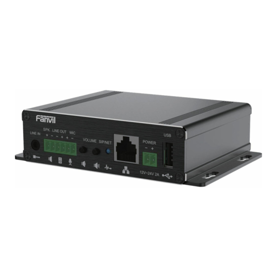
Overview PA3 is a SIP broadcast module specially developed for the needs of industry broadcast users. The media stream transmission adopts the standard IP/RTP/RTSP protocol. It integrates multiple functional interfaces: broadcast and intercom. It can realize audio broadcasting by connecting corresponding peripherals, and one-key call intercom and other practical functions. -
Page 9: Install Guide
For users who do not have POE equipment, the traditional power adaptor should be used. If the device is connected to both POE switch and external power adapter, PA3 will get power supply from POE switch in priority, and change to external power adapter once the POE power supply fails. -
Page 10: Function Key Led Status
5.2.2 Function key LED status Table 2- Function key LED status Type status SIP/NET Normally on Successfully Registered Fast Flashing Registration failed/network abnormality Slow Flashing In call... -
Page 11: User Guide
User Guide 6.1 Interface description Picture 1- Interface display Table 3- Interface Description Number Name Description Line in Audio signal input, used to connect external audio input. ○ interface Output the maximum power adaptively according to the input voltage of the equipment; Speaker 4Ω... -
Page 12: Installation Instructions
voltage 2.2V. It is recommended to use a shielded cable for the microphone signal line. Note: The shielding layer cannot be connected to any ground。 Volume Adjust the ringtone volume/call volume/broadcast volume; ○ down Long press the volume down button to report the IP address. Volume up Adjust the ringtone volume/call volume/broadcast volume. -
Page 13: Device Ip Address
6.2.2 Device IP address Method one: Open the web page and enter http://download.fanvil.com/tool/iDoorPhoneNetworkScanner.exe to download and install the IP scanning tool. Open the IP scanning tool, click the refresh button, search for the device and find the corresponding IP address. -
Page 14: Sip Configurations
Picture 2 - WEB Login The username and password should be correct to log in to the web page. The default username and password are "admin". For the specific details of the operation of the web page, please refer to 9 Web Configurations 6.4 SIP Configurations At least one SIP line should be configured properly to enable the telephony service. -
Page 15: Volume Setting
Picture 3 - SIP Line Configuration 6.5 Volume setting Set the volume (if the speaker or microphone is not connected, you can skip it) [Intercom Settings] >> [Media Settings] >> [Media Settings], as shown below, click [Submit]. Hands-free volume setting: Set the speaker output volume. Hands-free microphone gain: microphone volume level. -
Page 16: Set The Player Type
6.6 Set the player type Set the player type (the default is panel speaker mode) [Intercom Settings] >> [Media Settings] >> [Media Settings] The system defaults to the <panel speaker> mode, which is an intercom panel terminal with a shell. In order to ensure the voice effect of hands-free intercom and avoid damage to the speaker, When speaking, the output power is limited to less than 10W. -
Page 17: Basic Function
Basic Function 7.1 Making Calls After setting the function key to Hot key and setting the number, press the function key to immediately call out the set number, as shown below: Picture 6- Function Setting See detailed configuration instructions 9.26 Function Key 7.2 Answering Calls After setting up the automatic answer and setting up the automatic answer time, it will hear the ringing bell within the set time and automatically answer the call after timeout. - Page 18 the ring tone will be heard after the shutdown, and the auto-answer will not time out. Web interface: Enter [Line] >> [SIP], Enable auto answer and set auto answer time and click submit. Picture 7 - WEB line enable auto answer SIP P2P auto answering:...
-
Page 19: Call Waiting
7.5 Call Waiting Enable call waiting: new calls can be accepted during a call. Disable call waiting: new calls will be automatically rejected and a busy signal will be prompted Enable call waiting tone: when you receive a new call on the line, the device will beep. ... -
Page 20: Advance Function
Enable Intercom the SIP header call-info of the Call request Command automatic call If the option is enabled, PA3 will answer the intercom call Enable Intercom Barge automatically while it is in a normal call, and it will reject new... - Page 21 multicast listening address without involving SIP signaling. You can specify up to 10 multicast listening addresses. Picture 12 - MCAST Table 7- MCAST Parameters Description Enable Auto Mcast Send the multicast configuration information by Sip Notify signaling, and the device will configure the information to the system for multicast listening or cancel the multicast listening in the system after receiving the information Auto Mcast Timeout Delete...
-
Page 22: Hotspot
the multicast address, and select the codec. Click Apply. Set up the name, host and port of the receiving multicast on the web page of [Intercom Settings] >> [MCAST]. Press the DSSKey of Multicast Key which you set. ... - Page 23 SIP line Client Settings: As a SIP hotspot client, there is no need to set up a SIP account, which is automatically acquired and configured when the device is enabled. Just change the mode to "client" and the other options are set in the same way as the hotspot. Picture 13 - SIP hotspot The device is the hotspot server, and the default extension is 0.
-
Page 24: Web Configurations
Web Configurations 9.1 Web Page Authentication Users can log into the device's web page to manage user device information and operate the device. Users must provide the correct user name and password to log in. If the password is entered incorrectly three times, it will be locked and can be entered again after 5 minutes. The details are as follows: If an IP is logged in more than the specified number of times with a different user name, it ... -
Page 25: System >> Account
9.3 System >> Account Picture 14- WEB Account On this page the user can change the password for the login page. Users with administrator rights can also add or delete users, manage users, and set permissions and passwords for new users System >>... - Page 26 Picture 15 - System Setting Export Configurations Right click to select target save as, that is, to download the device's configuration file, suffix “.txt”. (note: profile export requires administrator privileges) Import Configurations Import the configuration file of Settings. The device will restart automatically after successful import, and the configuration will take effect after restart Clear Configurations ...
-
Page 27: System >> Upgrade
System >> Upgrade Picture 16- Upgrade Upgrade the software version of the device, and upgrade to the new version through the webpage. After the upgrade, the device will automatically restart and update to the new version. Click select, select the version and then click upgrade. Upgrade the ringtone,support wav and MP3 format. - Page 28 Picture 17 - Web page firmware upgrade Table 9- Firmware upgrade Parameter Description Upgrade server Enable automatic upgrade, If there is a new version txt Enable Auto Upgrade and new software firmware on the server, phone will show a prompt upgrade message after Update Interval. Upgrade Server Address1 Set available upgrade server address.
-
Page 29: System >> Auto Provision
Webpage: Login and go to [System] >> [Auto provision]. Picture 18- Auto provision settings Fanvil devices support SIP PnP, DHCP options, Static provision, TR069. If all of the 4 methods are enabled, the priority from high to low as below: PNP>DHCP>TR069>... - Page 30 Auto provision Parameters Description Basic settings Shows the current config file’s version. If the version of the downloaded configuration file is same with this one, the Current Configuration configuration file will not be applied. If the device confirm the Version configuration by the Digest method, once the configuration of server is modified or the device’s configurations are different from server’s, the device will download and apply the configurations.
- Page 31 support the feature will respond and send a Notify with URL to phone. Phone could get the configuration file with the URL. Server Address Broadcast address. As default, it is 224.0.0.0. Server Port PnP port Transport PnP protocol, TCP or UDP. Protocol Update Interval PnP message interval.
-
Page 32: System >> Fdms
System >> FDMS Picture 19 - FDMS Table 11- FDMS FDMS information Settings Community Designations Name of equipment installation community Building a movie theater Name of equipment installation building room number Equipment installation room name 9.8 System >> Tools This page gives the user the tools to solve the problem. Picture 20 - Tools... -
Page 33: Network >> Basic
Syslog:When enabled, set the syslog software address, and log information of the device will be recorded in the syslog software during operation. If there is any problem, log information can be analyzed by Fanvil technical support. 9.9 Network >> Basic This page allows users to configure network connection types and parameters. -
Page 34: Network >> Service Port
Network parameters must be entered manually and will not change. All Static IP parameters are provided by the ISP. DHCP Network parameters are provided automatically by a DHCP server. Account and Password must be input manually. These are provided by PPPoE your ISP. - Page 35 Picture 22- Service port setting interface Table 13- Server Port parameter description Web server type Restart after setting takes effect. Optional web login as HTTP/HTTPS Web login timeout The default is 15 minutes, the timeout will automatically log out of the login page, and you need to log in again Web page automatic No need to enter the user name and password after the timeout,...
-
Page 36: Vpn
9.11 VPN Picture 23- Network VPN Virtual Private Network (VPN) is a technology to allow device to create a tunneling connection to a server and becomes part of the server’s network. The network transmission of the device may be routed through the VPN server. For some users, especially enterprise users, a VPN connection might be required to be established before activate a line registration. - Page 37 status. There may be some delay of the connection establishment. User may need to refresh the page to update the status. Once the VPN is configured, the device will try to connect to the VPN automatically when the device boots up every time until user disable it. Sometimes, if the VPN connection does not established immediately, user may try to reboot the device and check if VPN connection established after reboot.
-
Page 38: Network >> Advanced
9.12 Network >> Advanced Picture 24 - Network Setting Network advanced Settings are typically configured by IT administrators to improve the quality of device service. Table 14- Network Setting Field Name Explanation LLDP Settings Enable LLDP Enable or disable LLDP Packet Interval LLDP Send detection cycle Enable Learning Function... -
Page 39: Lines >> Sip
Password Confirm Password 9.13LINES >> SIP... - Page 40 Picture 25- SIP Table 15 - SIP Parameters Description Register Settings Line Status Display the current line status at page loading. To get the up to date line status, user has to refresh the page manually. Server Address Enter the IP or FQDN address of the SIP server...
- Page 41 Server Port Enter the SIP server port, default is 5060 Authentication User Enter the authentication user of the service account Authentication Password Enter the authentication password of the service account Username Enter the username of the service account. Display Name Enter the display name to be sent in a call request.
- Page 42 Call Forward Number for No Answer Set the number of call forward on no answer Call Forward Delay for No Answer Set the delay time of not answered call before being forwarded Transfer Timeout Set the timeout of call transfer process Conference Type Set the type of call conference, Local=set up call conference by the device itself, maximum...
- Page 43 Advanced Settings Use Feature Code When this setting is enabled, the features in this section will not be handled by the device itself but by the server instead. In order to control the enabling of the features, the device will send feature code to the server by dialing the number specified in each feature code field.
- Page 44 Convert URI Convert not digit and alphabet characters to %hh hex code Use Quote in Display Name Whether to add quote in display name, i.e. “Fanvil” vs Fanvil Enable GRUU Support Globally Routable User-Agent URI (GRUU) Sync Clock Time Time Sycn with server...
-
Page 45: Line >> Sip Hotspot
Response Single Codec If setting enabled, the device will use single codec in response to an incoming call request BLF Server registered server will receive subscription package from ordinary application of BLF phone. Please enter the BLF server, if the sever does not support subscription package, the registered server and subscription server will be separated. - Page 46 Picture 27 - Line Basic Setting Table 16- Line Basic Setting Parameters Description STUN Settings Server Address Set the STUN server address Server Port Set the STUN server port, default is 3478 Binding Period Set the STUN binding period which can be used to keep the NAT pinhole opened.
-
Page 47: Intercom Settings >> Features
9.16 Intercom settings >> Features Picture 28 - Feature Table 17- Common device function Settings on the web page Parameters Description Basic Settings Enable Call Waiting Enable this setting to allow user to take second incoming call during an established call. Default enabled. The phone will hang up and return to the idle automatically at Enable Auto Handdown hands-free mode... - Page 48 Set the device to accept Active URI command from specific IP address. Source IP More details please refer to this link https://www.fanvil.com/Support/download/cid/14.html Push XML Server Configure the Push XML Server, when phone receives request, it will determine whether to display corresponding content on the phone which sent by the specified server or not.
-
Page 49: Intercom Settings >> Media
Reject Response Code Set the SIP response code on call rejection 9.17 Intercom settings >> media Picture 29- Media Settings Table 18- Audio Settings Parameters Description Codecs Settings Select the enabled and disabled voice codecs codec:G.711A/U,G.722,G.723,G.729,G.726-32, ILBC,AMR,AMR-WB Audio Settings Default Ring Type Set the default ring type. -
Page 50: Intercom Settings>>Camera Settings
ILBC Payload Length Set the ILBC Payload Length Enable VAD Enable Voice Activity Detection. When enabled, the device will suppress the audio transmission with artificial comfort noise signal to save the bandwidth. Enable Line-in enable or disable the linein function Enable Line-out enable or disable the lineout function Speaker... - Page 51 Picture 30- Camera Settings Table 19- Camera Settings Parameters Description camera settings Auto mode:The camera automatically makes the most appropriate adjustments according to the color temperature of the shooting scene, and automatically compensates for the color of the light source.。 Lock mode:Fixed white balance parameters will not be automatically adjusted according to the actual color temperature.
- Page 52 environment, no need for the operator to adjust Manual mode:Manually set the camera's contrast parameters. Contrast refers to the contrast between light and dark in the picture. Increase Contrast the contrast, the brighter areas will be brighter and the darker areas will be darker, and the contrast between light and dark will increase.
- Page 53 Stream VBR: Video call will adapt to the bit rate of the opposite end, so that the video Bitrate Control effect is better. CBR:The video call will not change according to the bit rate set by itself. Resolution Support 1080P,720P,4CIF,VGA,CIF,QVGA The larger the value is, the more fluent the video is, and the higher the Frame Rate (fps) requirement for network bandwidth is;...
-
Page 54: Intercom Setting >> Mcast
URL for various actions performed by the phone. These actions are recorded and sent as xml files to the server. Sample format is http://InternalServer /FileName.xml Picture 32- Action URL Note! The operation URL is used by the IPPBX system to submit device events. Please refer to the details Fanvil Action URL 。... -
Page 55: Intercom Setting >> Time/Date
9.21 Intercom Setting >> Time/Date Users can configure the device's time Settings on this page. Picture 33 - Time/Date Table 21- Time/Date Time/Date Explanation Field Name Network Time Server Settings Time Synchronized via SNTP Enable time-sync through SNTP protocol... -
Page 56: Intercom Settings>>Time Plan
Week Start The DST start week Weekday Start The DST start weekday Hour Start The DST start hour Month End The DST end month Week End The DST end week Weekday End The DST end weekday Hour End The DST end hour Manual Time Settings To set the time manually, you need to disable the SNTP service first, and you need to fill in and submit each item of year, month, day, hour and minute in the figure above to make the manual settings... -
Page 57: Intercom Settings >> Tone
Local: select the audio file uploaded locally U disk: select the audio file under the U disk SD card: select the audio file under the SD card Audio settings Select the audio file you want to play, it supports trial listening, and you can play it immediately after clicking the trial listening Repeat cycle Do not repeat: execute once within the set time range... -
Page 58: Call List >> Web Dial
the blacklist. User can add specific number to be blocked, or a prefix where any numbers matched the prefix will all be blocked. Restrict Outgoing Call You can set the rule to restrict some numbers from dialing out,until you remove the number from the table. -
Page 59: Function Key
9.26Function key Picture 37- Function Key Table 23- Function Key Parameters Description Function key settings memory Speed Dial:The user can directly dial the set number. This feature is convenient for customers to dial frequent numbers. Intercom: This feature allows the operator or secretary to quickly connect to the phone, widely used in office environments... - Page 60 Key event The user can select a function key as a shortcut to trigger an event for example: None /Handfree DTMF Press during a call to send the set DTMF Mcast Paging Configure the multicast address and voice encoding. User can initiate multicast by pressing this key Action URL The user can use a specific URL to make basic calls to the device, open...
- Page 61 Desktop Long None: Long press the speed dial key does not respond Pressed Main menu: Long press the speed dial key to enter the command line mode, see 5.2.1 Common Command Mode for details Advanced Settings Number 1 call number 2 mode selection. <Main/Secondary>: If the first number is not answered within the set time, Hot Key Dial Mode the second number will be automatically switched.
- Page 62 of the account intercom function, the call can be called automatically answered. party Multicast Multicast function is to deliver voice streams to configured multicast address; all equipment monitored the multicast address can receive and play the broadcasting. Using multicast functionality would make deliver voice one to multiple which are in the multicast group simply and conveniently.
-
Page 63: Security >> Web Filter
9.27Security >> Web filter Users can set up to allow only a certain network segment IP to access the device Picture 41- WEB filter Add and delete the allowed IP network segments; configure the start IP address in the start IP, configure the end IP address in the end IP, and then click [Add] to add successfully. -
Page 64: Security >> Device Certificates
Picture 42 - Trust Certificates 9.29Security >> Device Certificates Select the default certificate or the custom certificate as the device certificate. You can upload and delete uploaded certificates. Picture 43- Device Certificates... -
Page 65: Security >> Firewall
9.30Security >> Firewall Picture 44 - Firewall Through this page, you can set whether to enable the input and output firewalls, and at the same time, you can set the input and output rules of the firewall. Use these settings to prevent malicious network access, or restrict internal users from accessing some resources of the external network, and improve safety. -
Page 66: Device Log
all addresses 0.0.0.0; it can also be a network address similar to *.*.*.0, such as 192.168.1.0. The destination address can be a specific IP address or all Dst Mask addresses 0.0.0.0; it can also be a network address similar to *.*.*.0, such as 192.168.1.0. -
Page 67: Security Settings
9.32Security settings Enable Tamper: after enable, when the device is removed by force, the alarm information will be sent to the server and the alarm ring will be played. Picture 47 - Security Settings Table 27- Security Settings Security settings Parameters Description Basic settings... - Page 68 If the alarm ring needs to be stopped, the remote end can send a short Reset message to the terminal. The content of the short message is the value set in command the reset command. At this time, the terminal will stop playing the alarm bell Reset Alarm Reset to stop the playing of the bell Status...
-
Page 69: Trouble Shooting
[Stop] button on the webpage after completion. Network packets during the device are saved in a file. Users can analyze the packet or send it to the Fanvil Technical Support mailbox. -
Page 70: Get Device Log
1. The device is powered by external power supply via power adapter or POE switch. Please use standard power adapter provided by Fanvil or POE switch met with the specification requirements and check if device is well connected to power source.
Need help?
Do you have a question about the PA3 and is the answer not in the manual?
Questions and answers