Advertisement
Connect to main
chassis ground
+12V
KEY ON POWER
(fused 5 - 20 AMP max)
This Bus Interface Module has inputs for up to two thermocouple probe sensors, Dakota Digital part numbers SEN-11
or SEN-12. Each input can be configured individually. There are two interface (I/O) ports on the module. Either one
can be connected to the gauge system or to another module, allowing several units to be daisy chained together. Do
not connect the I/O port to anything other than a Dakota Digital gauge or BIM. Do not mount the module in the engine
compartment; it should be mounted in interior of the vehicle. The sensor harness cannot be extended with standard
wire. The sensors are available with different length harnesses. If you need a longer harness, contact Dakota Digital.
Each sensor connected to the bus needs a unique ID number assigned to it. This module has two inputs so it can use
one or two ID numbers. Each of the two inputs can be assigned an ID from 1 – 16, or turned off. The factory default
ID numbers are 11 and OFF for the two inputs respectively. The factory default labels are EGT and HEAD
respectively.
Labels available for each input are:
EGT -
Exhaust gas temperature input. This will display EGT, E, or EGT TEMP.
EGT A -
Exhaust gas temperature input. This will display EGT A, EA, or EGT TEMP A.
EGT B -
Exhaust gas temperature input. This will display EGT B, EB, or EGT TEMP B.
HEAD -
Cylinder head temperature input. This will display HEAD, HT, or HEAD TEMP.
HEAD A -
Cylinder head temperature input. This will display HEAD A, HA, or HEAD TEMP A.
HEAD B -
Cylinder head temperature input. This will display HEAD B, HB, or HEAD TEMP B.
Specs for each input are:
Sensor
HEAD -
SEN-11-4/5/6/7/8
EGT -
SEN-12-4/5/6/7
Temperature unit will follow the unit set for the main water temp gauge, Fahrenheit or Celsius.
Sender harness lengths:
SEN-11-4
6 feet with ½" ring
SEN-11-5
10 feet with ½" ring
SEN-11-6
14 feet with ½" ring
SEN-11-7
18 feet with ½" ring
SEN-11-8
18 feet with 14mm ring
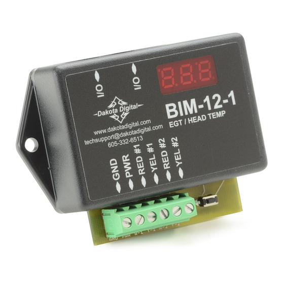
Bus Interface Module for EGT and Head Temp
(Sensors are sold separately)
To gauge control box
or another BIM
BIM-12-1
www.dakotadigital.com
techsupport@dakotadigital.com
EGT / HEAD TEMP
605-332-6513
Cut and strip sensor wire ends to insert into terminals
resolution
2°F
5°F
BIM-12-1
SEN-11-4/5/6/7/8 Head Temp probe
The probe extension has a red and yellow wire. Connect red to RED and yellow to YEL terminals.
setup/status switch
Channel 2 probe connection
Channel 1 probe connection
high warning
300 – 600
1140 – 1760
SEN-12-4
6 feet
SEN-12-5
10 feet
SEN-12-6
14 feet
SEN-12-7
18 feet
SEN-12-9
weld-on bung
SEN-12-4/5/6/7 EGT probe
MAN#650361C
Advertisement
Table of Contents

Subscribe to Our Youtube Channel
Related Manuals for Dakota Digital BIM-12-1


Summary of Contents for Dakota Digital BIM-12-1
- Page 1 Do not connect the I/O port to anything other than a Dakota Digital gauge or BIM. Do not mount the module in the engine compartment;...
- Page 2 Mounting the cylinder head temperature sensor: The sensor ring terminal can be installed under a cylinder head bolt on the engine or installed under a spark plug. Using, or not using, the crush washer on the spark plug is up to the individual. It should not make that much difference if it is used.
- Page 3 When you are finished, select BACK to return to the BIM list menu, select BACK to return to the main menu, and then select EXIT SETUP to return to normal operation. With HDX systems the setup can also be done with the Dakota Digital app for Apple and Android devices. Troubleshooting quick tips: While the BIM is operating, the dot in the upper left corner of the display will indicate the status.
- Page 4 Dakota Digital’s option. This warranty does not cover nor extend to damage to the vehicle’s systems, and does not cover diagnosis, removal or reinstallation of the product.
Need help?
Do you have a question about the BIM-12-1 and is the answer not in the manual?
Questions and answers