Table of Contents
Advertisement
Quick Links
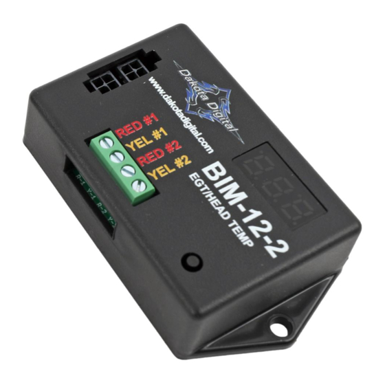
This Bus Interface Module has inputs for up to two thermocouple probe sensors, Dakota Digital part numbers SEN-11
or SEN-12. Each input can be configured individually. There are two interface (I/O) ports on the module. Either one
can be connected to the gauge system or to another module, allowing several units to be daisy chained together. Do
not connect the I/O port to anything other than a Dakota Digital gauge or BIM. Do not mount the module in the engine
compartment; it should be mounted in interior of the vehicle. The sensor harness cannot be extended with standard
wire. The sensors are available with different length harnesses. If you need a longer harness, contact Dakota Digital.
Each sensor connected to the bus needs a unique ID number assigned to it. This module has two inputs so it can use
one or two ID numbers. Each of the two inputs can be assigned an ID from 1 – 16, or turned off. The factory default
ID numbers are 11 and OFF for the two inputs respectively. The factory default labels are EGT and HEAD
respectively.
Labels available for each input are:
EGT -
Exhaust gas temperature input. This will display EGT, E, or EGT TEMP.
EGT A -
Exhaust gas temperature input. This will display EGT A, EA, or EGT TEMP A.
EGT B -
Exhaust gas temperature input. This will display EGT B, EB, or EGT TEMP B.
HEAD -
Cylinder head temperature input. This will display HEAD, HT, or HEAD TEMP.
HEAD A -
Cylinder head temperature input. This will display HEAD A, HA, or HEAD TEMP A.
HEAD B -
Cylinder head temperature input. This will display HEAD B, HB, or HEAD TEMP B.
Specs for each input are:
Sensor
HEAD -
SEN-11-4/5/6/7/8
EGT -
SEN-12-4/5/6/7
Temperature unit will follow the unit set for the main water temp gauge, Fahrenheit or Celsius.
Sender harness lengths:
6 feet with ½" ring
SEN-11-4
10 feet with ½" ring
SEN-11-5
14 feet with ½" ring
SEN-11-6
18 feet with ½" ring
SEN-11-7
SEN-11-8
18 feet with 14mm ring
Bus Interface Module for EGT and Head Temp
(Sensors are sold separately)
resolution
2°F
5°F
BIM-12-2
high warning
300 – 600
1140 – 1760
SEN-12-4
6 feet
SEN-12-5
10 feet
SEN-12-6
14 feet
SEN-12-7
18 feet
SEN-12-9
weld-on bung
MAN#650780
Advertisement
Table of Contents

Related Manuals for Dakota Digital BIM-12-2


Summary of Contents for Dakota Digital BIM-12-2
- Page 1 Do not connect the I/O port to anything other than a Dakota Digital gauge or BIM. Do not mount the module in the engine compartment;...
- Page 2 To set or change the ID numbers: The ID will not normally need to be changed. The following procedure will allow the BIM-12-2 to automatically select a new, unused set of ID’s. Make sure that all of the senders are connected first.
- Page 3 When you are finished, select BACK to return to the BIM list menu, select BACK to return to the main menu, and then select EXIT SETUP to return to normal operation. With HDX/RTX systems the setup can also be done with the Dakota Digital app for Apple and Android devices. Troubleshooting quick tips: While the BIM is operating, the dot in the upper left corner of the display will indicate the status.
- Page 4 SERVICE AND REPAIR DAKOTA DIGITAL offers complete service and repair of its product line. In addition, technical support is available to help you work through any questions or problems you may be having installing one of our products. Please read through the Troubleshooting Guide. There, you will find the solution to most problems.
Need help?
Do you have a question about the BIM-12-2 and is the answer not in the manual?
Questions and answers