Sign In
Upload
Manuals
Brands
Gotting Manuals
Antenna
HG G-98830
Gotting HG G-98830 Manuals
Manuals and User Guides for Gotting HG G-98830. We have
2
Gotting HG G-98830 manuals available for free PDF download: Operating Manual
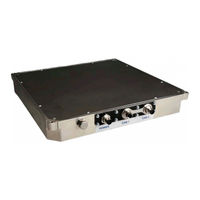
Gotting HG G-98830 Operating Manual (110 pages)
Transponder-Antenna 2-dimensional Position Detection & Identification Outdoor, flat Design
Brand:
Gotting
| Category:
Antenna
| Size: 2 MB
Table of Contents
Table of Contents
3
1 About this Operating Manual
6
Validity
6
Target Group
6
Additional Applicable Documents
6
Declaration of Conformity
7
Presentation of Information
7
Warning Notices
7
Symbols
8
Table 1 Hazard Classification According to ANSI Z535.6-2006
8
Definitions
9
Reading and Mounting Side
9
Coordinate System of the Antenna
9
Figure 1 Figure 1 Reading and Mounting Side of the Transponder Antenna
9
Figure 2 Output Polarity (for Sign and Coordinate Output)
9
Abbreviations
10
Table 2 Abbreviations
10
2 Safety Instructions
11
Intended Use
11
Improper Use
11
User Qualification
12
General Safety Instructions
12
Obligations of the Operator
13
3 Scope of Delivery
14
Required Accessories
14
Table 3 Required Accessories
14
Optional Accessories
15
Table 4 Optional Accessories
15
4 Device Overview
16
System Components
16
Components in the Ground
16
Transponders
16
Figure 3 System Components (Excerpt)
16
Structure of the Transponder Code
17
Transponder Antenna
17
Figure 4 Transponder Antenna HG G-98830YA
17
5 Operating Principle
18
Position Detection with Transponders
18
Figure 5 Examples of Driverless Vehicles with Transponders
18
Track Guidance with Transponders
19
Figure 6 Sketch: Position Detection with Transponders
19
Figure 7 Sketch: Track Guidance with Odometry and Transponders
19
Position Detection with a Navigation Controller
20
Figure 8 Sketch: Track Guidance / Free Navigation with Transponders
20
6 Storage
22
7 Mounting
23
Mounting the Transponders
23
Operating Conditions for Transponders
23
Preparation of Connection Cables
24
Connecting POWER
24
Connecting the CAN Bus
24
Table 5 Pin Allocation POWER
24
Mounting the Transponder Antenna
25
Operating Conditions of the Antenna
25
Minimum Distance between Antenna and Transponder
25
Table 6 Pin Allocations CAN1 and CAN2
25
Minimum Distance between Identical Transponder Antennas
26
Minimum Distance to Current-Carrying Wires Around the Transponder Antenna
26
Figure 9 Minimum Distance between Identical Transponder Antennas
26
Figure 10 Minimum Distance to Current-Carrying Wires Around the Transponder an
26
Connection Example
27
Figure 11 Metal-Free Areas Around the Transponder Antenna
27
Figure 12 Connection Example
27
Mounting the Antenna on the Vehicle
28
Figure 13 Mounting on or in Metal
28
Figure 14 Position of the Mounting Holes and Dowel Pin Cut-Outs
28
Figure 15 Specifications for Dowel Pins on the Vehicle Floor
29
Figure 16 Mounting with M6 Screws
29
Figure 17 Mounting with M5-Screws
29
Antenna Switch-On
30
8 Commissioning
31
Connecting the Antenna to a Computer
31
Figure 18 Example of Connection: Connection to the Serial Interface of a Computer
31
Configuring the Terminal Program
32
Figure 19 Setting the COM Port in Hyperterminal
32
Table 7 Settings in the Terminal Program
32
Configuring the Antenna (Monitor Program)
33
Set Parameters
33
Minimize Interferences
33
Finish Commissioning
33
9 Interfaces
35
Posipulse
35
Serial Interface (RS232)
35
Figure 20 Connection Options Positioning Pulse
35
List of System Values that Can be Output
36
Figure 21 Equation: Minimum Update Rate
36
Table 8 Bytes and Data Words of a Telegram with 24 Byte Length
36
Table 9 Possible System States
37
List of System Commands
38
Table 10 List of System Commands
38
CAN Bus
41
Definitions CAN and Canopen
41
Table 11 Definitions Can/Canopen
41
Operating Modes and States
42
Table 12 Canopen®: Parameter PDO Operating Mode
42
Table 13 Canopen®: PDO Operating Modes
42
Table 14 CAN: Bit and Byte Sequences
42
Table 15 Canopen®-Operation Mode
42
Can
43
CAN Message Object - Y-Identifier, Send Object
43
CAN Message Object - X-Identifier, Send Object
43
CAN Message Object - D-Identifier, Send Object
43
Table 16 Structure of the CAN Message Object - y Identifier
43
Table 17 Structure of the CAN Message Object - X Identifier
43
Table 18 Structure of the CAN Message Object - D Identifier
43
CAN Message Object - P-Identifier, Send Object
44
CAN Message Object - S-Identifier, Send Object
44
CAN Message Object - Programming, Receive Object
44
Canopen
44
Table 19 Structure of the CAN Message Object Programming
44
Table 20 Coding of the Commands CAN Message Object Programming
44
Description of the Process Data Objects (PDO)
45
Table 21 Variables in PDO_1
45
Table 22 Variables in PDO_2
45
Heartbeat
46
Node-Guarding
46
Description of Service Data-Objects (Sdos)
46
Table 23 Variablen in PDO_3
46
Table 24 Codes of the Heartbeat Mode
46
Table 25 Identifier for Read and Write Access
46
Object Directory
47
Table 26 Possible Error Codes SDO Telegram
47
10 Configuration of the System Via the Service Interface
48
Starting the Monitor Program
48
Procedure Monitor Only
48
Procedure 3964R or Procedure Transparent
48
Table 27 Modes of the Serial Interface
48
Figure 22 Send File in Monitor Program
49
Using the Monitor Program
50
Main Menu
50
Figure 23 Main Menu of the Monitor Program
50
Display of System Variables and Status Messages
51
Table 28 Meanings of the System Variables (Monitor Program)
51
Activate Sub Menus
52
Setting and Permanently Saving Parameters
52
S)Erial Output
52
Figure 24 Menu: (S)Erial Output
53
Figure 25 Output at (D)Isplay Telegram Content
55
T)Ime & Code
56
Figure 26 Menu: (T)Ime & Code
57
F)Requency & Antenna Tuning
60
Figure 27 Menu: (F)Requency & Antenna Tuning
61
Figure 28 Equation: Calculation of the Receive Frequency for the Upper and Lower Sidebands
61
Basic C(A)N-Parameters
62
Figure 29 Menu: C(A)N-Parameters
62
CA(N)-Open-Parameters
65
Figure 30 Menu: CA(N)-Open-Parameters
66
D)Isplay Systemstatus
69
Cs(V)
69
Figure 31 Example of a CSV Text File
69
Y) Display Histogram
70
Figure 32 Importing CSV Data into a Spreadsheet (Using Excel® as an Example)
70
W)Rite Transponder
71
L)Oad Values to Eeprom
71
Figure 33 Menu: (Y) Display Histogram
71
U)Pdate Firmware
72
1) Import / (2) Export User Parameter
72
P(R)Int Parameters
73
11 Update the Antenna Software
74
Setting up the Update Program
74
Updating the Software
74
Figure 34 Update Program: the Operating Elements
75
12 Maintenance
76
13 Disposal
77
14 Troubleshooting
78
Error Table
78
Table 29 Error Table
78
Reducing Interferences
79
Which Interfering Influences Are There
79
What Happens When Crossing a Transponder
79
Setting Positioning Thresholds
80
Figure 35 Transponder Reading as CSV-File Imported into Excel with Comments
81
Figure 36 Positioning Threshold for a Normal Transponder Reading with Side Lobes
82
Figure 37 Test Drive over Several Transponders
82
15 Technical Data
83
General Data
83
Electrical Data
83
Table 30 General Data Antenna HG G-98830YA
83
Table 31 Electrical Data Antenna HG G-98830YA
83
Scale Drawing of the Antenna with Dimensions
85
Figure 38 Scale Drawing of the Antenna with Dimensions
85
16 Appendix
86
Signal Strength and Accuracy of Position Calculation
86
Figure 39 Signal Strength of Reference Voltage in X and y Direction with Transpon
86
Procedure 3964R
87
Data Direction Antenna -> PLC
87
Data Direction PLC -> Antenna
88
Procedure Transparent
88
Data Direction Antenna -> PLC
89
Data Direction PLC -> Antenna
89
Overview of the Canopen® Directory
89
Communication Specific Entries Within the Range of 0X1000 to 0X1Fff
89
Table 32 Overview Canopen® Object Directory I
89
Manufacturer Specific Entries Starting at 0X2000
91
Standardized Device Profile from 0X6000
91
Table 33 Overview Canopen® Object Directory II
91
Table 34 Overview Canopen® Object Directory III
91
Details of the Canopen® Directory
92
Device Type
92
Error Register
92
COB-ID SYNC Message
92
Device Name
92
Hardware-Version
92
Software-Version
92
Table 35 Canopen® Directory: Device Type
92
Table 36 Canopen® Directory: Error Register
92
Table 37 Canopen® Directory: COB-ID SYNC Message
92
Save Parameters
93
Restore Default Parameters
93
Producer Heartbeat Time
93
Table 41 Canopen® Directory: Save Parameters
93
Table 42 Canopen® Directory: Restore Default Parameters
93
Table 43 Canopen® Directory: Producer Heartbeat Time
93
Identity Object
94
Transmit PDO_1 Parameter
94
Transmit PDO_2 Parameter
94
Table 44 Canopen® Directory: Identity Object
94
Table 45 Canopen® Directory: Transmit PDO_1 Parameter
94
Table 46 Canopen® Directory: Transmit PDO_1 Parameter
94
Transmit PDO_3 Parameter
95
Mapping TPDO_1
95
Mapping TPDO_2
95
Table 47 Canopen® Directory: Transmit PDO_3 Parameter
95
Table 48 Canopen® Directory: Mapping TPDO_1
95
Table 49 Canopen® Directory: Mapping TPDO_2
95
Mapping TPDO_3
96
Table 50 Canopen® Directory: Mapping TPDO_3
96
Device Parameters
97
Table 51 Canopen® Directory: Device Parameters
97
Codes Relevant in Canopen® for System Configuration
98
Manufacturer Parameters - Node Parameters
98
Table 52 Canopen® Directory: Relevant Codes for the System Configuration
98
Table 53 Canopen® Directory: Manufacturer Parameters - Node Parameters
98
Bit Digital Input (Transmission in TPDO_2)
99
Bit Status (Transmission in TPDO_1)
99
32-Bit-Transponder-Code
99
8-Bit Analog Inputs
99
Table 54 Canopen® Directory: Manufacturer Parameters - Node Parameters / Baud Rates
99
Table 55 Canopen® Directory: 8 Bit Digital Input (Transmission in TPDO_2)
99
Table 56 Canopen® Directory: 16 Bit Status (Transmission in TPDO_1)
99
Table 57 Canopen® Directory: 32 Bit Transponder Code
99
Table 58 Canopen® Directory: 8 Bit Analog Inputs
99
16-Bit-Analog-Inputs
100
CAN EDS Configuration File
100
Glossary
100
Table 59 Canopen® Directory: 16 Bit Analog Inputs
100
List of Figures - Chapter 17 101 List of Figures
101
17 List of Figures
101
18 List of Tables
103
19 Index
105
20 Copyright and Terms of Liability
108
Copyright
108
Exclusion of Liability
108
Trade Marks and Company Names
108
Advertisement
Gotting HG G-98830 Operating Manual (116 pages)
Transponder Antenna
Brand:
Gotting
| Category:
Antenna
| Size: 4 MB
Table of Contents
Details of the Canopen® Directory
5
Declaration of Conformity
8
Presentation of Information
8
Signal Word
8
Table 1 Hazard Classification According to ANSI Z535.6-2006
9
Figure 1 Reading and Mounting Side of the Transponder Antenna
10
Figure 2 Output Polarity (for Sign and Coordinate Output)
11
Table 2 Abbreviations
11
Safety Instructions
12
Intended Use
12
Improper Use
13
User Qualification
13
General Safety Instructions
14
Obligations of the Operator
14
Scope of Delivery
15
Table 3 Variant Overview
15
Required Accessories
15
Table 4 Required Accessories
16
Table 5 Optional Accessories
16
Device Overview
17
Figure 3 System Components (Excerpt)
17
Figure 4 Transponder Antenna HG G-98830YB/HG G-98835YB
18
Operating Principle
19
Figure 5 Examples of Driverless Vehicles with Transponders
19
Figure 6 Sketch: Position Detection with Transponders
20
Figure 7 Sketch: Track Guidance with Odometry and Transponders
20
Figure 8 Sketch: Track Guidance / Free Navigation with Transponders
21
Table 6 Pin Allocation POWER
25
Table 7 Pin Allocations CAN1 and CAN2
26
Table 8 PROFINET®: Pin Assignments Bus 1 & Bus 2
26
Figure 9 Minimum Distance between Identical Transponder Antennas
28
Figure 10 Minimum Distance to Current-Carrying Wires Around the Transponder Antenna
28
Figure 11 Metal-Free Areas Around the Transponder Antenna
29
Figure 12 Connection Example
29
Figure 13 Mounting on or in Metal
30
Figure 14 Position of the Mounting Holes and Dowel Pin Cut-Outs
31
Figure 15 Specifications for Dowel Pins on the Vehicle Floor
31
Figure 16 Mounting with M6 Screws
32
Figure 17 Mounting with M5-Screws
32
Figure 18 Connection Example: Connection to the Serial Interface of a Computer
34
Table 9 Terminal Settings for the Monitor Program
34
Figure 19 Screenshot: Tera Term
35
Figure 20 Screenshot: Tera Term -> Setup -> Serial Port
35
Figure 21 Screenshot: Tera Term -> File -> New Connection
36
Figure 22 Connection Options Positioning Pulse
38
Figure 23 Equation: Minimum Update Rate
39
Table 10 Bytes and Data Words of a Telegram with 24 Byte Length
39
Table 11 Possible System States
40
Table 12 List of System Commands
41
Table 13 Definitions Can/Canopen
45
Table 14 Canopen®: Parameter PDO Operating Mode
45
Table 15 Canopen®: PDO Operating Modes
45
Table 16 CAN: Bit and Byte Sequences
46
Table 17 Canopen® Operation Mode
46
Table 18 Structure of the CAN Message Object - y Identifier
46
Table 19 Structure of the CAN Message Object - X Identifier
47
Table 20 Structure of the CAN Message Object - D Identifier
47
Table 21 Structure of the CAN Message Object Programming
47
Table 22 Coding of the Commands CAN Message Object Programming
48
Table 23 Variables in PDO_1
49
Table 24 Variables in PDO_2
49
Table 25 Variablen in PDO_3
49
Table 26 Codes of the Heartbeat Mode
50
Table 27 Identifier for Read and Write Access
50
Table 28 Possible Error Codes SDO Telegram
50
Table 29 Structure of the PROFINET® Input Bytes
51
Table 30 Structure of the PROFINET® Output Bytes
51
Table 31 Addresses for the PROFINET® Read/Write Command
52
Table 32 Modes of the Serial Interface
53
Using the Monitor Program
55
Figure 24 Main Menu of the Monitor Program
55
Table 33 Meanings of the System Variables (Monitor Program)
56
Figure 25 Menu: (S)Erial Output
58
Figure 26 Output at (D)Isplay Telegram Content
60
Figure 27 Menu: (T)Ime & Code
62
Figure 28 Menu: (F)Requency & Antenna Tuning
66
Figure 29 Equation: Calculation of the Receive Frequency for the Upper and Lower Sidebands
66
Figure 30 Menu: C(A)N-Parameters
68
CA(N)-Open-Parameters
71
Figure 31 Menu: CA(N)-Open-Parameters
72
Figure 32 Example of a CSV Text File
75
Figure 33 Importing CSV Data into a Spreadsheet (Using Excel® as an Example)
77
Figure 34 Menu: (Y) Display Histogram
77
Figure 35 Screenshot: Bootloader Menu
79
Figure 36 Screenshot: Tera Term -> Transfer -> XMODEM -> SEND
79
Maintenance
81
Troubleshooting
83
Table 34 Error Table
83
Figure 37 Transponder Reading as CSV-File Imported into Excel with Comments
86
Figure 38 Positioning Threshold for a Normal Transponder Reading with Side Lobes
87
Figure 39 Test Drive over Several Transponders
87
Table 35 General Technical Data Antenna HG G-98830YB/HG G-98835YB
88
Figure 40 Scale Drawing of the Antenna with Dimensions
90
Figure 41 Signal Strength of Reference Voltage in X and y Direction with Transponder HW DEV00095 on the Respective Center Axes
91
Figure 42 Typical Accuracy of the Distance Calculation in X Direction (Driving Direction) with Transponder HW DEV00095
91
Figure 43 Typical Accuracy of the Deviation Calculation in y Direction (Trans- Verse to the Direction of Travel) with Transponder HW DEV00095
92
Figure 44 State Diagram Procedure 3964R; Antenna -> PLC
93
Figure 45 State Diagram Procedure 3964R; PLC -> Antenna
93
Device Type
94
Table
94
Index Subindex Name 0X1000
94
Error Register
94
Table 36 Overview Canopen® Object Directory I
94
Table 37
96
Table 37 Overview Canopen® Object Directory II
96
Table 38 Overview Canopen® Object Directory III
96
Table of Contents
97
COB-ID SYNC Message
97
Table 42
97
Device Name
97
Hardware-Version
97
Software-Version
97
Table 39 Canopen® Directory: Device Type
97
Table 40 Canopen® Directory: Error Register
97
Table 41 Canopen® Directory: COB-ID SYNC Message
97
Table 42 Canopen® Directory: Device Name
97
Type Attr. Map Default
98
Type Attr
98
Unsigned 8 RO no 0X00
98
Type Attr. Map Default Description
98
Attr. Map Default
98
Attr. Map Default Description
98
Appendix
98
Table 45 Canopen® Directory: Save Parameters
98
Table 46 Canopen® Directory: Restore Default Parameters
98
Table 47 Canopen® Directory: Producer Heartbeat Time
98
Table 48 Canopen® Directory: Identity Object
99
Table 49 Canopen® Directory: Transmit PDO_1 Parameter
99
Table 50 Canopen® Directory: Transmit PDO_1 Parameter
99
Table 51 Canopen® Directory: Transmit PDO_3 Parameter
100
Table 52 Canopen® Directory: Mapping TPDO_1
100
Table 53 Canopen® Directory: Mapping TPDO_2
101
Table 54 Canopen® Directory: Mapping TPDO_3
101
Table 55 Canopen® Directory: Device Parameters
102
Table 56 Canopen® Directory: Relevant Codes for the System Configuration
103
Table 57 Canopen® Directory: Manufacturer Parameters - Node Parameters
103
Table 58 Canopen® Directory: Manufacturer Parameters - Node Parameters
104
Table 59 Canopen® Directory: 8 Bit Digital Input (Transmission in TPDO_2)
104
Table 60 Canopen® Directory: 16 Bit Status (Transmission in TPDO_1)
104
Table 61 Canopen® Directory: 32 Bit Transponder Code
104
Table 62 Canopen® Directory: 8 Bit Analog Inputs
105
Table 63 Canopen® Directory: 16 Bit Analog Inputs
105
Table 64 Document Revision History
114
Exclusion of Liability
115
Advertisement
Related Products
Gotting HG G-98780-A
Gotting HG G-98760-C Series
Gotting HG G-98810-C
Gotting HG G-98870-A
Gotting HG G-98870
Gotting HG G-98870 ZA
Gotting HG G-98870 YA
Gotting HG G-98835
Gotting HG G-71910-C
Gotting HG G-71915
Gotting Categories
Antenna
GPS
Accessories
Marine Radio
Controller
More Gotting Manuals
Login
Sign In
OR
Sign in with Facebook
Sign in with Google
Upload manual
Upload from disk
Upload from URL