
Related Manuals for Netech LKG 610


Summary of Contents for Netech LKG 610
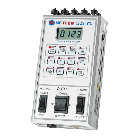
- Page 1 LKG 610 LKG 610 Electrical Safety Analyzer With 10 ECG Connectors INSTRUCTION MANUAL Netech Corporation 110 Toledo St, Farmingdale, NY 11735, http://www.NetechCorp.us http://www.PressureMeter.com...
-
Page 2: Table Of Contents
Controls & Indicators ..................11 Preparation for use ..................... 12 Operating Instructions ..................13 Performance check ..................... 16 Theory of Operation .................... 16 Maintenance and Storage .......... Maintenance ....................... 18 Calibration / Service ................... 18 Returning the LKG 610 for Calibration ..............19... -
Page 3: Warranty
Netech Corporation. Only serialized products are covered under this warranty. This warranty does not apply if the product has been damaged by accident or misuse or as the result of service or modification by other than Netech Corporation, or if its serial number is defaced or removed. -
Page 4: Notices (Patents / Copy Right, Trademarks)
Netech Corporation. Trademarks LKG 610 is trademarks of Netech Corporation. Any other trademark names used in this manual are only for editorial purposes and the benefit of the respective trademark owner with no intention of improperly using that trademark. -
Page 5: Returns & Credits
LKG 610 CAUTION The “CAUTION” sign denotes a hazard. It calls attention to a procedure, practice or the like, which, if not correctly performed or adhered to, could result in damage to or destruction of part or the entire instrument. Do not precede beyond a “CAUTION”... -
Page 6: Repair And Recalibration
Return Procedure All items being returned (including all warranty-claim shipments) must be sent freight- prepaid to our factory location. When you return an instrument to Netech Corporation, we recommend using United Parcel Service, Federal Express, DHL or Air Parcel Post. -
Page 7: Models And Part Numbers
LKG 610 Models and Part Numbers Part Number Description 535-110 10 Lead Electrical Safety Analyzer (110 V) 535-220 10 Lead Electrical Safety Analyzer (220 V) Standard Accessories Part Number Description Picture Test Lead for electrical analyzer 535-CASE Hard Carrying Case... -
Page 8: General Overview
AAMI ESI -1993 or the IEC 601-1 test load may be selected. Resistance measurements are made using the included model 503 single conductor test lead. A unique feature of the LKG 610 is its ability to verify the test readings with calibrated outputs of 200 µ Amps and 1 Ohm. -
Page 9: Specifications
LKG 610 Specifications Display: 3-1/2 Digit LCD Display LEAKAGE CURRENT: 0-1999 Micro Amps. All Current measurements are made through the AAMI/ANSI ES1-1985 or IEC 601-1 test load. The meter readings correspond to the true RMS value of the current. Accuracy: DC to 1 KHz: 1% FS + 1 LSD 1 Khz to 100 KHz: ±... -
Page 10: Instrument Familiarity
User Manual LKG 610 Instrument Familiarity... -
Page 11: Controls & Indicators
LKG 610 Controls & Indicators Item Name Description Universal connectors to connect ECG snaps or various sized posts Connectors Display A 3.5 digit LCD presents the result of the selected test measurement Load Selector A slide switch on the right side of the instrument to select either the Switch AAMI or the IEC 601-1 test load. -
Page 12: Preparation For Use
Preparation for Use The LKG 610 includes a test lead, part # 503, for measuring Cord Resistance and Case Leakage. Connect the LKG 610 to a 110 VAC outlet (or 220 VAC outlets for the 220 Volt Model). During the initial setup the last digit of the LCD will change gradually due to the time constant of the RMS to DC converter. -
Page 13: Operating Instructions
Operating Instructions 1. Line Voltage Measurement: The default measurement setting is line voltage (LINE VOLT). When the LKG 610 is plugged into an AC outlet, the LCD will display the measured line voltage in Volts. If the outlet polarity is reversed the display will indicate ‘- POL’ and line voltage will not be displayed. - Page 14 See Figure 2. Set the Polarity Switch to the OFF (center) position. Press the key marked “CHS RES”. Plug the DUT into the test receptacle. Using the 503 test lead, connect the chassis of the DUT to the CHASSIS jack on the LKG 610. The display will present the Cord Resistance in milliohms.
- Page 15 LKG 610 6. Leads Isolation Test: Plug the ECG device into the LKG 610. Connect the ECG leads. Press the “ISO TEST” key. The isolation leakage will be presented on the display in µAmps. After 30 seconds the LED will begin flashing to indicate that the applied isolation voltage has been removed.
-
Page 16: Performance Check
“EARTH LKG” key. The display will read 200 µA + 2%. Theory of Operation The LKG 610 circuitry can be divided into main functional blocks as shown in Figure 3. Each performs a key role in the operation of the instrument. - Page 17 LKG 610 Block Diagram Description Test Load: The input test load is user selectable to AAMI ESI –1993 or to IEC 601. RMS Converter and Amplifier: The input amplifier buffers the input. The RMS converter generates a DC voltage equal to the RMS value at its input. The gain Amplifier sets the gain for the measurements.
-
Page 18: Maintenance And Storage
Annual calibration is recommended. If the LKG 610 is returned to Netech for recalibration before the first year warranty expires, Netech will provide a second year warranty. The warranty is void if the LKG 610 is serviced by anyone other than Netech or if the warranty seal is broken. -
Page 19: Returning The Lkg 610 For Calibration
LKG 610 Returning the LKG 610 for Re-Calibration Products returned to Netech for repair or recalibration requires a RMA (Return Authorization Number) for speedy processing of the service required. To obtain a RMA number follow the link and fill in the required http://www.NetechCorp.us... - Page 20 User Manual LKG 610 Appendix This section is intentionally left blank for future use...
Need help?
Do you have a question about the LKG 610 and is the answer not in the manual?
Questions and answers