
Related Manuals for Netech UPM 2000


Summary of Contents for Netech UPM 2000
- Page 1 UPM 2000 Ultrasound Power Meter User Manual Manual P/N 1200-User-Manual Initial Release-3/12/2008...
- Page 2 UPM 2000 Netech Corporation 110 Toledo St, Farmingdale, NY 11735 http://www.Netech.org 1-800-547-6547...
-
Page 3: Table Of Contents
Chapter 4 Safety, Maintenance, and Storage ............39 Recommended Procedures and Precautions ................40 Calibration Check Procedures ....................... 40 Maintenance........................... 41 Service ............................41 Returning the UPM 2000 for Calibration ..................42 Battery Replacement........................42 Storage............................42 ....................Repackaging and Shipping Appendix Troubleshooting ........................ -
Page 4: Warranty
Netech Corporation, or if its serial number is defaced or removed. Netech reserves the right to discontinue the UPM 2000 at any time, and change its specifications, price, or design without notice and without incurring any obligation. -
Page 5: Notices
UPM 2000 Notices Copyright Copyright © 2008 by Netech Corporation. All rights reserved. No part of this publication may be reproduced or transmitted in any form other than for the purchaser’s personal use without written permission from Netech Corporation. Quality Assurance Netech is ISO 9001-2000 Certified. - Page 6 Netech Corporation, we recommend using United Parcel Service, Federal Express, or Air Parcel Post. We also recommend that you insure your shipment for its actual replacement cost. Netech Corporation will not be responsible for lost shipments or instruments that are received in damaged condition due to improper packaging or handling.
- Page 7 UPM 2000 Repair and Calibration Products returned for repair or recalibration must obtain the service form which can be down loaded from our website www.Netech.org/service or contact: Netech Corporation Service Dept. 110 Toledo Street New York, 11735 Tel: 1-631-531-0100 Email: Service@Netech.org WARNING Unauthorized user modifications or application beyond the ...
-
Page 8: Safety Considerations
UPM 2000 Safety Considerations Use of this instrument is restricted to qualified personnel who recognize shock hazards and are familiar with safety precautions used when operating electrical equipment. Read the manual carefully before operating the UPM2000. The following warning symbols may be found on the UPM2000:... -
Page 9: Hazard Warnings
UPM 2000 Hazard Warnings ∗ Warning! Power Rating. The UPM 2000’s mains power input must be connected to an external power transformer that provides voltage and current within the specified rating for the system. Use of an incompatible power transformer may produce electrical shock and fire hazards. -
Page 10: Electromagnetic Interference And Susceptibility
UPM 2000 Based on the testing standards below, this device bears the mark. Electromagnetic Interference and Susceptibility USA FCC CLASS A Warning: Changes or modifications to this unit not expressly approved by the manufacturer could void the user's authority to operate the equipment. This equipment has been tested and found to comply with the limits for a Class A digital device, pursuant to Part 15 of the FCC Rules. -
Page 11: Ec Directives
UPM 2000 Immunity The system has been type tested by an independent, accredited testing laboratory and found to meet the latest harmonized European emissions and immunity standard requirements of EN 61326 for commercial measurement equipment. Verification of compliance was conducted to the limits and methods of the... - Page 12 UPM 2000 Netech Corporation 110 Toledo St, Farmingdale, NY 11735 http://www.Netech.org 1-800-547-6547...
-
Page 13: Chapter 1 General Information
UPM 2000 Chapter 1: General Information Inside This Chapter • Summary of Features • Ultrasound and its Applications • Patient Treatment with Therapeutic Ultrasound Netech Corporation 110 Toledo St, Farmingdale, NY 11735 http://www.Netech.org 1-800-547-6547... -
Page 14: Summary Of Features
The instrument measures output through a strain gauge bridge transducer. After the initial output is verified, the UPM 2000 is used to accurately calibrate the ultrasound unit under test. In addition, the UPM 2000: •... -
Page 15: Ultrasound And Its Application
UPM 2000 Ultrasound and Its Applications Human perception of sound waves is limited to frequencies of fewer than 20,000 vibrations per second. Higher frequency vibrations — between 0.7 and 3.3 MHz — are used for ultrasound therapy. (Most ultrasound equipment produces an output of between 1 and 3.3 MHz.) -
Page 16: Patient Treatment With Therapeutic Ultrasound
The most essential assurance that the clinician can have is the verification that the ultrasound unit is producing the ultrasound energy for which it was designed. The Netech UPM 2000 digital power meter enables the clinician to accurately measure this output energy. -
Page 17: Chapter 2 Description
UPM 2000 Chapter 2: Description Inside This Chapter • Specifications • Overall Unit Layout • Front Panel Description • Back Panel Description • Standard Accessories • Optional Accessories Netech Corporation 110 Toledo St, Farmingdale, NY 11735 http://www.Netech.org 1-800-547-6547... -
Page 18: Upm 2000 Specifications
UPM 2000 UPM 2000 Specifications • Measurement range 0.1 to 30 Watts • Input Power Level 0 - 30 W • Input Frequency 0.5 - 10 MHz • Resolution 0.1 W • Accuracy, electrical +/- .15 W (+/-.01 grams) throughout range •... -
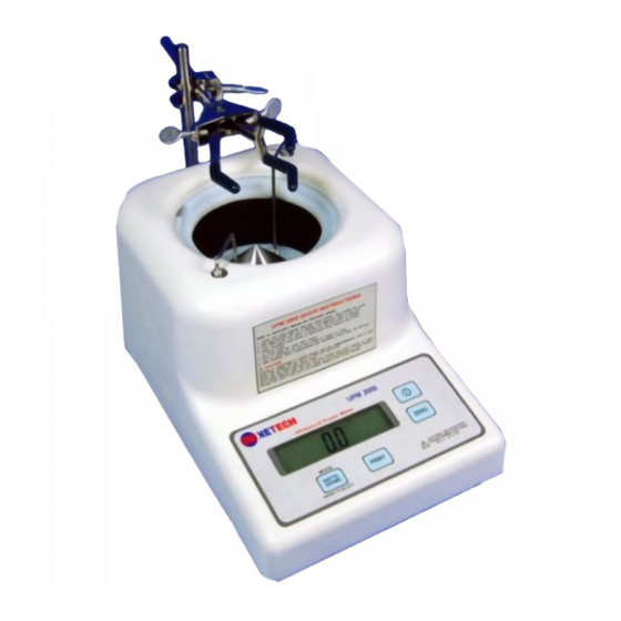
Page 19: Overall Unit Layout
Support Post Cone Hanger Leveling Bubble Figure 2-1: UPM 2000 General Layout The top of the UPM 2000 Ultrasound Power meter is shown in Figure 2-1. It includes the following components. • Front Panel: Includes LCD readout and keyboard. •... -
Page 20: Front Panel Description
UPM 2000 Front Panel Description Figure 2-2: UPM 2000 Front Panel Layout The front panel of the UPM 2000 ultrasound power meter is shown in Figure 2-2. It includes the following components: • LCD Display: Indicates the meter reading in watts or grams. -
Page 21: Back Panel Description
UPM 2000 Back Panel Description The back panel of the UPM 2000 is shown in Figure 2-3. It includes the following components: • Battery Compartment: Allows access to the instrument's 9 V dc battery. The hinged plastic battery cover opens to expose the battery compartment during battery replacement. -
Page 22: Bottom Panel Description
UPM 2000 Bottom Panel Description The bottom panel of the UPM 2000 is shown in Figure 2-4. It includes the following components: • Leveling Jacks: There are three support legs located on the bottom panel, two of which are threaded to be able to act as leveling jacks for the height adjustment to level the unit. -
Page 23: Standard Accessories
• Shipping Container: This box contains specifically designed foam inserts to ensure safe shipment of the UPM 2000 Power meter. Please save these for future shipment of the unit for service or calibration. The Carrying Case is an integral piece of the shipping container. Ship Note: with the carrying case in its original packing. -
Page 24: Optional Accessories
Optional Accessories • Dissolved Oxygen Test Kit: Tests the dissolved oxygen content of the degassed water. To order this kit, request Netech PN 1200-O2KIT. • RS-232 Cable: Used for hooking the unit up to a computer or a serial printer. PN 1200-B-232 •... -
Page 25: Chapter 3 Installation And The Operating Environment
Chapter 3: Installation & the Operating Environment Inside This Chapter • Unpacking and Inspection • Operation • UPM 2000 Systems Check • Beginning Ultrasound Power Measurements • Using the Universal Transducer Clamp Assembly and Centering Rings • Ultrasound Unit Testing •... -
Page 26: Unpacking And Inspection
Be sure to save the box and packing materials. They will be needed when you return the UPM 2000 to Netech for recalibration or future service. (Refer to Chapter 4 for shipping instructions.) If there is no shipping damage, continue removing the carrying case, with the UPM 2000 in it, from the shipping case. - Page 27 UPM 2000 • Cone Hanger • Clamp Support Post • Universal Transducer Clamp • Hook Clamp • 100 gram calibration ch k weight • Calibration weight adapter pedestal • Centering Rings (3) • 9 Volt Battery • Power Transformer • Carrying Case ...
-
Page 28: Operation
Operating Environment The UPM 2000 must be allowed to adjust to room temperature before the unit can be operated. The relative humidity in the room should not exceed 90%. Refer t o Chapter 4 for additional information on safety, storage and shipping requir ements for the UPM 2000. - Page 29 Distilled and degassed water must be used as the coupling medium to obtain stable and accurate readings with the UPM 2000. The water must also be allowed to reach room temperature before pouring into tank in order for unit to stabilize quickly.
-
Page 30: Upm 2000 Systems Check
Transformer Unit Power Jack 3. Allow sufficient time for the UPM 2000 to fully adjust to room temperature. If the unit is not at room temperature, the transducer will be slowly warming or cooling and will cause the readings to shift. - Page 31 Fill the tank with 600 ml ± 50 ml of fresh distilled and degassed water. Do not spill water on the panel of the UPM 2000. Fill until the water reaches slightly above the bottom lip of the well, as shown below.
-
Page 32: Beginning Ultrasound Power Measurements
45 minutes to 1 hour. 2. Tu rn on the UPM 2000 using the ON switch on the front panel. Ensure that the unit is in the Watts mode (displayed units will read 0). - Page 33 4. Turn on the ultrasound unit following the manufacturer’s instructions. Adjust it to the desired level. Never exceed thirty watts. 5. Read the actual output power in WATTS on the LCD of the UPM 2000. 6. After all of the readings are completed, shut off the ultrasound unit.
-
Page 34: Using The Universal Transducer Clamp Assembly And Centering Rings
UPM 2000 Using the Universal Transducer Clamp Assembly and Centering Rings The universal transducer clamp assembly frees the operator from ho lding the transducer treatment (radiating) head in the coupling water and prevents transducer movement, ensuring more accurate and stable readings. The centering rings help to properly center and aim the transducer head in the tank. - Page 35 UPM 2000 Figure A Figure B Clamp orientation Clamp orientation transducer without transducer with handle handle 5. Open the clamp by turning the clamp thumbscrews counterclockwise to fit the desired transducer head or handle. Tighten the clamp screw to effectively grab the transd ucer head or handle.
-
Page 36: Ultrasound Unit Testing
A serial printer or a computer may be connected to the UPM 2000 via this port. Printing with the UPM 2000 means that the LCD contents are sent to the printer whenever the Print key on the UPM 2000’s front panel is pressed. -
Page 37: Using The Rs232 Port
Commu nication with the UPM 2000 is full duplex. There are two commands that may be sent to the UPM 2000 in the form of two byte 7-bit ASCII strings: Escape P returns the current LCD contents as 22 characters including terminating return and linefeed characters. - Page 38 UPM 2000 Netech Corporation 110 Toledo St, Farmingdale, NY 11735 http://www.Netech.org 1-800-547-6547...
-
Page 39: Chapter 4 Safety, Maintenance, And Storage
Chapter 4: Safety, Maintenance & Storage Inside This Chapter • Recommended Procedures and Precautions • Calibration Check Procedures • Maintenance • Service • Returning the UPM 2000 for Calibration • Battery Replacement • Storage • Repackaging and Shipping Netech Corporation 110 Toledo St, Farmingdale, NY 11735 http://www.Netech.org... -
Page 40: Recommended Procedures And Precautions
Do not spill water on the front or rear panel. Do not apply more than 30 W of input power to the UPM 2000. Do not operate the UPM 2000 for more than 1 hour during testing. Change the water between extended tests. -
Page 41: Maintenance
Service The mechanical assembly of the UPM 2000 contains no parts that can be serviced by the user. The unit should be returned to Netech Biomedical for repair or calibration. The alignment and adjustment parameters are critical to the performance of the UPM 2000 and can be performed only at the factory or designated distributor. -
Page 42: Returning The Upm 2000 For Calibration
The storage environment should be fr ee of dust and other foreign particles. The UPM 2000 must have the cone removed and be fully drained for storage. Permanent damage may result if this is not done. The UPM 2000 can be stored under the following environmental... -
Page 43: Repackaging And Shipping
UPM 2000 Repackaging and Shipping When the UPM 2000 is shipped to Netech for service or repair, the unit must be shipped in the original packing and carrying case; other forms of commercially available packing are not recommended and can void the warranty. - Page 44 Carrying Case Operator’s Manual storage ring Figure 4-2 Place the gray foam padding insert around the UPM 2000 unit in the carrying bag as shown in Figure 4-2. Zip the canvas bag cover closed. Netech Corporation 110 Toledo St, Farmingdale, NY 11735 http://www.Netech.org...
- Page 45 UPM 2000 Pack the UPM 2000 in its original packing material and shipping box. FAILURE TO USE THE ORIGINAL PACKAGING MATERIAL MAY RESULT IN DAMAGE TO THE UNIT AND VOID THE WARRANTY! Proper placement of the foam inserts when re-using the original packaging...
- Page 46 UPM 2000 Netech Corporation 110 Toledo St, Farmingdale, NY 11735 http://www.Netech.org 1-800-547-6547...
-
Page 47: Appendix Troubleshooting
UPM 2000 Appendix A: Troubleshooting Guide Netech Corporation 110 Toledo St, Farmingdale, NY 11735 http://www.Netech.org 1-800-547-6547... - Page 48 UPM 2000 The UPM 2000 will display an error code if improper use or an abnormal condition is detected. Consult the following table for possible error codes, the probable cause, and corrective action. Error Description Corrective Action Code Indicates that an under-load is sensed.
- Page 49 RS-232 Port Communication failures between the UPM 2000 and a printer or a PC are usually caused by the serial cable or incorrect parameter settings. Troubleshoot as follows: 1. Verify that the correct serial cable is being used. The correct cable is Netech PN: 1200-B- 232 or equivalent 9-pin “straight-through”...
- Page 50 Netech Biomedical Service Cent er 631-53 1-0100 for how to get out of the Service Menu Codes without affect ing the opera tion of your UPM 2000 and voiding the warranty. Netech Corporation 110 Toledo St, Farmingdale, NY 11735 http://www.Netech.org...
Need help?
Do you have a question about the UPM 2000 and is the answer not in the manual?
Questions and answers