
Related Manuals for Netech LKG 601


Summary of Contents for Netech LKG 601
- Page 1 INSTRUCTION MANUAL LKG 601 Electrical Safety Analyzer 110 Toledo Street • Farmingdale, NY 11735 • USA http://www.Netech.org 510-USER-Manual Rev3 10/29/2007...
- Page 2 601 will deliver years of high performance and accuracy. This instruction manual has been designed as a tool to assist you in getting the most from your LKG 601. In order to properly use and to maintain this instrument, please read the manual carefully.
- Page 3 Netech Corporation. This warranty does not apply if the product has been damaged by accident or misuse, or as the result of service or modification by other than Netech Corporation, or if its serial number is defaced or removed.
- Page 4 Netech reserves the right to discontinue the LKG 601 at any time, and change its specifications, price, or design without notice and without incurring any obligation. Netech guarantees availability of service parts for 5 years after the manufacture of the unit is discontinued.
-
Page 5: Safety Considerations
Safety Considerations General Before operation, instrument related documentation must be reviewed for familiarization with all safety markings and instructions Safety Symbols WARNING The “WARNING” sign denotes a hazard. It calls attention to a procedure, practice or the like, which, if not correctly performed or adhered to, could result in personal injury. -
Page 6: Table Of Contents
General Description Controls and Indicators Preparation for use Operating Instructions Maintenance Theory of Operation Specifications Instructions for Return LIST OF FIGURES Figure 1 Front view-LKG 601 Figure 2 Block Diagram, Cord Resistance and Case Leakage Measurements Figure 3 Functional Block Diagram... -
Page 7: General Description
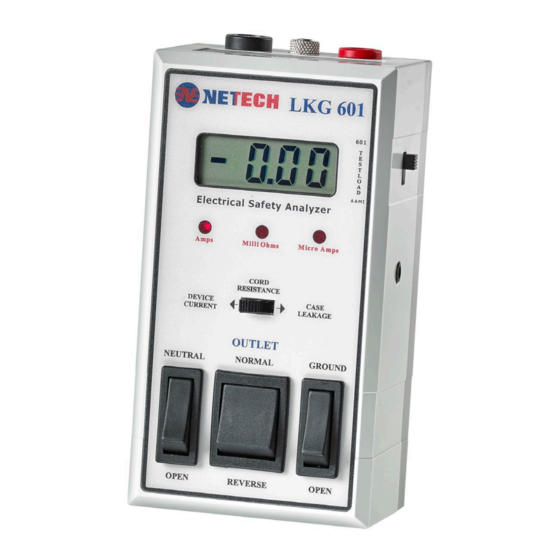
GENERAL DESCRIPTION The LKG 601 is a compact, low cost Electrical Safety Analyzer designed to evaluate the basic electrical safety of all electrical systems including medical devices physiological instrumentation. The LKG 601 measures Electrical Leakage Current, Power Cord Ground Resistance, and Device Current. - Page 8 Test Receptacle Power Cable Figure 1 Front view of the LKG 601...
-
Page 9: Controls And Indicators
CONTROLS AND INDICATORS 1. DISPLAY: A 3½ Digit LCD indicates the result of the measurement being made. 2. LEDS: 3 red LEDS indicate the selected test mode. 3. MODE SWITCH: Three-position slide switch to select the test measurement. A lit red LED indicates the selection. - Page 10 11. TEST JACKS: calibrated output provided at the test jack for resistance and current functions. This performs a self-check of the LKG 601. 12. ZERO ADJUSTMENT: This recessed adjustment allows for the zeroing of the display to eliminate test cable resistance variations.
-
Page 11: Preparation For Use
CAUTION Make sure that the power requirements of the Device Under Test are within the power ratings of the LKG 601, 15 amps at 110 volts and 10 amps at 230 volts. CAUTION leave... -
Page 12: Operating Instructions
• Using the test lead provided, connect the chassis of the Device Under Test to the Case Ground jack on the LKG 601. • The display will indicate the Power Cord Resistance in milliohms. Case Ground... - Page 13 CASE LEAKAGE CURRENT MEASUREMENTS: Move the Mode switch to CASE LEAKAGE. See Figure 2. The Earth Leakage (or Ground Leakage) Current is measured through the ground conductor of the Device Under Test. This is only applicable to devices with a three- conductor power cord.
- Page 14 Netech trained personnel. PERFORMANCE CHECK Connect the LKG 601 to a live 110 VAC (or 220 VAC for the LKG 601-220) outlet. Display will turn on and read 0 ± 1 when the Mode switch is in the Case Leakage position.
- Page 15 Connect the Test Lead to the TEST JACK. Move selector switch CORD RESISTANCE. The reading should be 1010 milliohms + 5%. Move the switch to CASE LEAKAGE. The display will indicate 200 Micro Amps + 2%. These tests will confirm that the LKG 601 is working properly.
-
Page 16: Maintenance
601 is returned to Netech for recalibration before the first year warranty expires Netech will provide a second year warranty. The warranty is void if the LKG 601 is serviced by anyone other than Netech or if the warranty seal is broken. -
Page 17: Theory Of Operation
THEORY OF OPERATION The LKG 601 circuitry can be divided into main functional blocks as shown in Figure 3. Each performs a key role in the operation of the instrument. AAMI or RMS TO IEC 601 LEDS CURRENT SOURCE TEST... - Page 18 Current Source and Amplifier: Resistance is measured by connecting the current source to the resistance to be measured and measuring the voltage with the input amplifier. Test Receptacle: This supplies power to the unit under test, 110 VAC rated at 15 Amps (220 VAC).
-
Page 19: Specifications
SPECIFICATION S METER: 3-1/2 Digit LED display. LEAKAGE CURRENT: 0-1999 Micro Amps. All Current measurements are made through the AAMI/ANSI ES1-1985 or IEC 601-1 test load. The meter readings correspond to the true RMS value of the current. Accuracy: ± 1% of reading, + 1 LSD DC to 1 KHz, ±... - Page 20 PHYSICAL DIMENSIONS: Size: 5.5x 3.25 x 2.5 Inches Weight: 1 lbs (.45kg) ENVIRONMENTAL: Operating range: 59 to 95 F (15 to 40 Storage Temperature: 0 to 122 F (-20 to 60 Relative Humidity: 90% (max) at temperatures STANDARD ACCESSORIES: Description Part Number User Manual 510-MANUAL...
-
Page 21: Instructions For Return
INSTRUCTIONS FOR RETURN Damaged in Transit: shipments carefully examined NETECH and carefully packaged for shipment. They are insured in the customer’s name with the carrier. On receipt, if the shipping container appears have been damaged during shipment, the instrument should be thoroughly inspected. - Page 22 5. Include the completed Service Form. 6. Ship the instrument to the following address: NETECH CORPORATION 110 Toledo Street Farmingdale, NY 11735 ATTN: SERVICE DEPT. For the latest Revisions and updates visit...
- Page 23 LKG 601 Quick check for Resistance and Leakge functions. TOP PANEL CONNECTORS 3 FUSE 2 TEST JACK (METAL) 1 CASE GROUND (RED) OUTLET GROUND OUTLET 1‐Connect 503 cable between CASE GROUND (RED) to TEST JACK (METAL).(Between 1 to 2).Select CASE LKG , Display will read between 197 to 203. 2‐Connect 503 cable between CASE GROUND and TEST JACK . (Between 1 to 2). Select CORD RESISTANCE . Display will read 1050‐1100 Approximately. This will include the total resistance of 1000 milliohms (internal resistor)+ Lead resistance which is typically 20 to 80 milliohms.. 3‐Connect 503 cable between CASE GROUND to Outlet GROUND.(Between 1 to OUTLET GROUND). CORD RESISTANCE selected. Display will read 0000.If not Zero it by using a small Phillips screwdriver. Turn the screw located on the RIGHT side of LKG601. It is Located next to the test load selector switch. ...
Need help?
Do you have a question about the LKG 601 and is the answer not in the manual?
Questions and answers