
Related Manuals for Netech LKG 610


Summary of Contents for Netech LKG 610
- Page 1 INSTRUCTION MANUAL LKG 610 Electrical Safety Analyzer With 10 ECG Connectors 110 Toledo Street • Farmingdale, NY 11735 • USA Homepage: www.netech.org...
- Page 2 This instruction manual has been designed as a tool to assist you in getting the most from your LKG 610. In order to properly use and to maintain this instrument, please read the manual carefully. Netech is recognized as an innovative designer and manufacturer of advanced biomedical and industrial test instruments.
- Page 3 Netech Corporation. This warranty does not apply if the product has been damaged by accident or misuse, or as the result of service or modification by other than Netech Corporation, or if its serial number is defaced or removed.
- Page 4 Netech reserves the right to discontinue the LKG 610 at any time, and change its specifications, price, or design without notice and without incurring any obligation. Netech guarantees availability of service parts for 5 ars after the manufacture of the unit is discontinued.
- Page 5 Safety Considerations General Before using the LKG 610 read the instruction manual and become familiar with all of the functions and controls. Safety Symbols WARNING The “WARNING” sign denotes a hazard. It calls attention to a procedure, practice or the like, which, if not correctly performed or adhered to, could result in personal injury.
-
Page 6: Table Of Contents
Preparation for use Operating Instructions Performance Check Maintenance Theory of Operation Specifications Appendix Instructions for Return LIST OF FIGURES Figure 1 Front View LKG 610 Figure 2 Block Diagram, Cord Resistance and Case Leakage Measurements Figure 3 Functional Block Diagram... -
Page 7: General Description
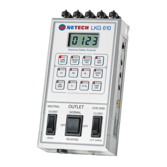
ESI -1993 or the IEC 601-1 test load may be selected. Resistance measurements are made using the included model 503 single conductor test lead. A unique feature of the LKG 610 is its ability to verify the test readings with calibrated outputs of µ Amps and 1 Ohm. - Page 8 Figure 1 Front view of the LKG 610...
-
Page 9: Controls And Indicators
CONTROLS AND INDICATORS 1. ECG CONNECTORS: Universal connectors to connect ECG snaps or various sized posts. 2. DISPLAY: A 3.5 digit LCD presents the result of the selected test measurement. 3. LOAD SELECTOR SWITCH: Slide switch selects the AAMI or the IEC 601-1 test load. 4. - Page 10 11. ZERO ADJUSTMENT: Recessed adjustment to zero any test cable resistance variations. 12. TEST RECEPTACLE: 20 Amp hospital grade receptacle for the Device Under Test. 13. POWER CORD: Power cord and hospital grade plug. 14. KEY PAD: Twelve push button function keys to select the test measurement.
-
Page 11: Preparation For Use
PREPARATION FOR USE The LKG 610 includes a test lead, part # 503, for measuring Cord Resistance and Case Leakage. Connect the LKG 610 to a 110 VAC outlet (or 220 VAC outlet for the 220 Volt Model). Before proceeding with any measurement become familiar with the measurements and the function selector keys. -
Page 12: Operating Instructions
OPERATING INSTRUCTIONS 1. LINE VOLTAGE MEASUREMENT: The default measurement setting is line voltage (LINE VOLT). When the LKG 610 is plugged into an AC outlet, the LCD will display the measured line voltage in Volts. If the outlet polarity is reversed the display will indicate ‘- POL’... - Page 13 “CHS RES”. Plug the DUT into the test receptacle. Using the 503 test lead, connect the chassis of the DUT to the CHASSIS jack on the LKG 610. The display will present the Cord Resistance in milliOhms. DUT Power Cord...
- Page 14 LKG 610 introduces line voltage into the patient leads. Even though it is current limited to 1milliAmp, it is potentially lethal. Plug the ECG device into the LKG 610. Connect the ECG leads. Press the “ISO TEST” key. The isolation leakage will be presented on the display in µAmps.
- Page 15 has been removed. The previous leakage measurement will be displayed. To perform another ISO test press the “ISO TEST” key again. 7. CASE LEAKAGE CURRENT: The Case Leakage Current is measured through the test lead cable. Connect the test Lead to the case of the DUT(Device under test).
-
Page 16: Performance Check
PERFORMANCE CHECK The following tests will confirm that the LKG 610 is performing properly. Connect the LKG 610 to a 110 VAC outlet (220 VAC for the LKG 610-220). The power on default function is “Line Volt”. The LCD display will present the line voltage in Volts. -
Page 17: Maintenance
Leakage and Cord Resistance functions. When making a resistance measurement with a Test Cable other than the one supplied with the LKG 610, the user can zero the leads with the zero adjustment potentiometer. This will not affect the internal calibration of the unit. -
Page 18: Theory Of Operation
THEORY OF OPERATION The LKG 610 circuitry can be divided into main functional blocks as shown in Figure 3. Each performs a key role in the operation of the instrument. AAMI or RMS TO IEC 601 LEDS CURRENT SOURCE TEST... - Page 19 INPUT AMPLIFIER, and the voltage developed across it from the leakage current is measured. Current Source and Amplifier: Resistance is measured by connecting the current source to the resistance to be measured and measuring the voltage with the input amplifier. Test Receptacle: This supplies power to the unit under test, 110 VAC rated at 15 Amps (220 VAC).
-
Page 20: Specifications
SPECIFICATIONS METER: 3-1/2 Digit LED display. LEAKAGE CURRENT: Current measurements are made through the AAMI/ANSI ES1-1985 or IEC 601-1 test load. Meter readings correspond to the true RMS value of the current. Range: 0 to 1999 microAmps Accuracy: DC to 1 KHz: 1% FS + 1 LSD 1 Khz to 100 KHz: ±... - Page 21 POWER REQUIREMENTS: 110 VAC 50-60Hz, 20 Amps (535 Model) 220 VAC, 10 Amps (535-220 Model) PHYSICAL DIMENSIONS: Size: 8.0 X 4.5 X 2.0 inches (20.3 X 11.4 X 5.0 cm) Weight: 2.5 lbs (1.1 kg) ENVIRONMENTAL: Operating range: 59 to 95 F (15 to 35 Storage Temperature: 0 to 122 F (-18 to 50...
Need help?
Do you have a question about the LKG 610 and is the answer not in the manual?
Questions and answers