Table of Contents
Advertisement
Advertisement
Table of Contents
Troubleshooting

Related Manuals for Enterasys Matrix E1 1H582-25


Summary of Contents for Enterasys Matrix E1 1H582-25
-
Page 1: Installation Guide
Matrix E1 Series (1H582-25 and 1H582-51) Installation Guide 9033680-05... - Page 3 Enterasys Networks reserves the right to make changes in specifications and other information contained in this document without prior notice. The reader should in all cases consult Enterasys Networks to determine whether any such changes have been made. The hardware, firmware, or software described in this manual is subject to change without notice.
-
Page 4: Fcc Notice
FCC NOTICE This device complies with Part 15 of the FCC rules. Operation is subject to the following two conditions: (1) this device may not cause harmful interference, and (2) this device must accept any interference received, including interference that may cause undesired operation. -
Page 5: Safety Compliance
Warning: Fiber Optic Port Safety When using a fiber optic media expansion module, never look at the transmit laser while it is powered on. Also, never look directly at the fiber TX port and fiber cable ends when they are powered on. -
Page 6: Safety Information
6. Bei der Aufstellung des Gerätes ist auf sicheren Stand zu achten. Ein Kippen oder Fallen könnte Beschädigungen hervorrufen. 7. Die Belüftungsöffnungen dienen der Luftzirkulation, die das Gerät vor Überhitzung schützt. Sorgen Sie dafür, daß diese Öffnungen nicht abgedeckt werden. 8. -
Page 7: Program License Agreement
CAREFULLY READ THIS LICENSE AGREEMENT. This document is an agreement (“Agreement”) between the end user (“You”) and Enterasys Networks, Inc. on behalf of itself and its Affiliates (as hereinafter defined) (“Enterasys”) that sets forth Your rights and obligations with respect to the Enterasys software program (including any accompanying documentation, hardware or media) (“Program”) in the... - Page 8 52.227-19 (a) through (d) of the Commercial Computer Software-Restricted Rights Clause and its successors, and (iii) in all respects is proprietary data belonging to Enterasys and/or its suppliers. For Department of Defense units, the Program is considered commercial computer software in accordance with DFARS section 227.7202-3 and its successors, and use, duplication, or disclosure by the Government is subject to restrictions set forth herein.
- Page 9 Enterasys and, accordingly, You hereby agree to maintain complete books, records and accounts showing (i) license fees due and paid, and (ii) the use, copying and deployment of the Program. You also grant to Enterasys and its authorized representatives, upon reasonable notice, the right to audit and examine during Your normal business hours,...
-
Page 10: Declaration Of Conformity
Manufacturer’s Address: European Representative Address: Conformance to Directive(s)/Product Standards: Equipment Type/Environment: Networking Equipment, for use in a Commercial Enterasys Networks, Inc. declares that the equipment packaged with this notice conforms to the above directives. 73/23/EEC 50 Minuteman Road Andover, MA 01810 Enterasys Networks Ltd. -
Page 11: Table Of Contents
Figures ... xiii Tables...xiv ABOUT THIS GUIDE Who Should Use This Guide...xv Structure of This Guide ...xvi How to Use This Guide ... xvii Related Documents... xvii Document Conventions... xviii INTRODUCTION Overview ... 1-1 Connectivity... 1-3 Standards Compatibility ... 1-5 Getting Help ... - Page 12 3.5.2 Installing Optional Mini-GBICs ... 3-13 Installing the Device ... 3-16 3.7.1 3.7.2 3.7.3 3.7.4 Connecting to the Network... 3-21 3.8.1 3.8.2 3.8.3 3.8.4 3.8.5 Connecting to Console Port for Local Management ... 3-30 3.9.1 3.9.2 3.9.3 3.9.4 3.9.5 3.10 Completing the Installation...
- Page 13 OPTIONAL INSTALLATIONS AND MODE SWITCH BANK SETTINGS Required Tools...B-1 Removing the Chassis Cover...B-2 Setting the Mode Switches...B-4 SIMM Replacement Procedure ...B-6 B.4.1 B.4.2 B.4.3 GBIC SPECIFICATIONS Gigabit Ethernet Specifications ... C-1 C.1.1 C.1.2 C.1.3 Physical and Environmental Specifications... C-4 Regulatory Compliance... C-4 INDEX Locating SIMMs ...B-6...
-
Page 15: Figures
Figure Matrix E1 1H582-xx Standalone Ethernet Switch Devices... 1-2 Optional Ethernet Expansion Modules (Port 1 identified)... 1-4 Removing the Front Panel Coverplate ... 3-5 Installing the Ethernet Expansion Module ... 3-6 Different Physical Styles of GBICs ... 3-8 Installing a Side Clip GBIC ... 3-9 GBIC Metal Locking Bar Positions ... - Page 16 Tables Table Optional Ethernet Expansion Modules, Compliance, and Physical Connection ...1-4 Contents of 1H582-51 Carton ...3-2 LANVIEW LEDs ...4-3 Troubleshooting Checklist...4-4 Device Specifications () ... A-2 Ethernet Expansion Module Input/Output Port Specifications ... A-3 GBIC Input/Output Port Specifications... A-4 Console Port Pin Assignments ... A-5 Compliance Standards...
-
Page 17: Important Notice
1H582-xx. For information about the Command Line Interface (CLI) set of commands used to configure and manage the 1H582-xx, refer to the Enterasys Networks™ Matrix E1 Series (1G582-xx and 1H582-xx) Configuration Guide. -
Page 18: Structure Of This Guide
STRUCTURE OF THIS GUIDE This guide is organized as follows: Chapter 1, Introduction, provides an overview of the 1H582-xx, the optional Ethernet expansion modules, and explains how to contact Enterasys Networks for technical support. Chapter 2, Network Requirements, outlines the network requirements that must be met before installing the 1H582-xx. -
Page 19: Hardware Installation
HOW TO USE THIS GUIDE For... An overview of the 1H582-xx features, and getting technical support from Enterasys Networks Network requirements that must be met before installing the device Installing the device hardware Diagnosing network/operational problems using the LANVIEW LEDs... -
Page 20: Document Conventions
Document Conventions DOCUMENT CONVENTIONS This guide uses the following conventions: NOTE: Calls the reader’s attention to any item of information that may be of special importance. TIP: Conveys helpful hints concerning procedures or actions. CAUTION: Contains information essential to avoid damage to the equipment. ELECTRICAL HAZARD: Warns against an action that could result in personal injury or death due to an electrical hazard. -
Page 21: Introduction
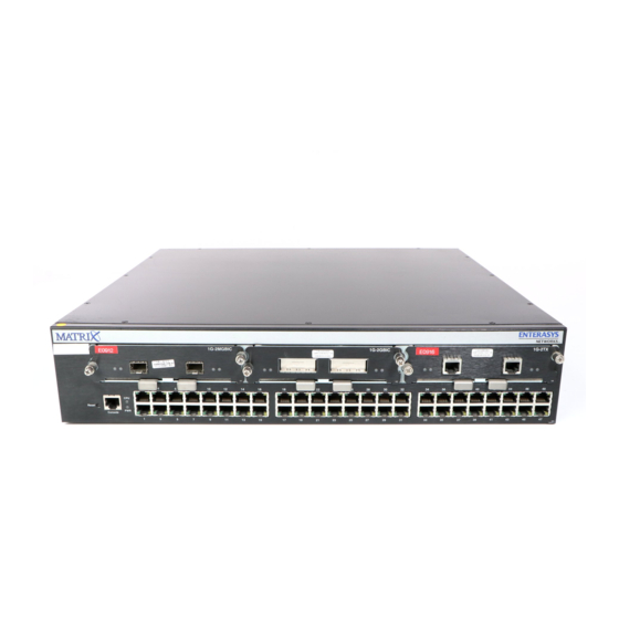
This chapter introduces the Matrix E1 1H582-xx standalone devices. Depending on the firmware version used in the device, some features described in this document may not be supported. Refer to the Release Notes shipped with the 1H582-xx to determine which features are supported. - Page 22 Each power supply module supports its own ac input connection, which enables each power supply to be connected to a different ac power circuit for power source redundancy. Figure 1-1 Matrix E1 1H582-xx Standalone Ethernet Switch Devices à Â...
-
Page 23: Connectivity
CAUTION: The expansion modules are NOT hot-swappable. The switch must be powered down before the expansion modules are installed or removed. Hot-swapping the expansion modules while the switch is powered on could cause the device to stop forwarding frames. Table 1-1... - Page 24 Connectivity Figure 1-2 Optional Ethernet Expansion Modules (Port 1 identified) Table 1-1 Optional Ethernet Expansion Modules, Compliance, and Physical Connection Ethernet Expansion Module... 1H-16TX 1G-2TX 1G-2GBIC 1G-2MGBIC 1H-8FX Introduction Compliant to... With... 10/100BASE-TX Sixteen, fixed RJ45 connectors 1000BASE-TX Two fixed RJ45 connectors 1000BASE-SX/LX Two slots for optional GBICs (GBICs have one SC connector)
-
Page 25: Standards Compatibility
A description of any action(s) already taken to resolve the problem (e.g., changing mode switches, rebooting the unit, etc.) • The serial and revision numbers of all involved Enterasys Networks products in the network • A description of your network environment (layout, cable type, etc.) •... -
Page 27: Network Requirements
NOTE: The Matrix E1 Series (1G582-xx and 1H582-xx) Configuration Guide and Cabling Guide referred to in the following sections can be found on the Enterasys Networks World Wide Web site: PORT TRUNKING FEATURE Before connecting the device to a network so it can take advantage of the Port Trunking feature, there are certain rules concerning port connections and configurations that must be followed for proper operation. -
Page 28: 10Base-T Network
10BASE-T Network 10BASE-T NETWORK When connecting a 10BASE-T segment to one of the RJ45 fixed front-panel ports, or to an optional Ethernet expansion module, ensure that the network meets the Ethernet network requirements of the IEEE 802.3 standard for 10BASE-T. Refer to the Cabling Guide for details. NOTE: If a port is to operate at 100 or 1000 Mbps, Category 5 cabling must be used. -
Page 29: Hardware Installation
ELECTRICAL HAZARD: Only qualified personnel should install the 1H582-xx. NOTE: Read the Release Notes shipped with the device to check for any exceptions to the supported features and operation documented in this guide. This chapter provides the instructions required to install the 1H582-xx. Follow the order of the sections as listed below to correctly install the device. -
Page 30: Unpacking The Device
3. Remove the tape seal on the non-conductive bag to remove the device. 4. Perform a visual inspection of the device for any signs of physical damage. Contact Enterasys Networks if there are any signs of damage. Refer to Hardware Installation Table 3-1. -
Page 31: Installing Options
CAUTION: The expansion modules are NOT hot-swappable. The switch must be powered down before the expansion modules are installed or removed. Hot-swapping the expansion modules while the switch is powered on could cause the device to stop forwarding frames. The 1H582-51 has three expansion slots for optional Ethernet expansion modules. At the time of this printing, five Ethernet expansion module options were available for the 1H582-51. -
Page 32: Installing An Optional Ethernet Expansion Module
Installing an Optional Ethernet Expansion Module INSTALLING AN OPTIONAL ETHERNET EXPANSION MODULE NOTE: Install any optional equipment before proceeding to CAUTION: An antistatic wrist strap is required to perform the following procedures to minimize ESD damage to the devices involved. Installing an Ethernet expansion module involves the following: •... -
Page 33: Installing An Ethernet Expansion Module
CAUTION: The expansion modules are NOT hot-swappable. The switch must be powered down before the expansion modules are installed or removed. Hot-swapping the expansion modules while the switch is powered on could cause the device to stop forwarding frames. Refer to... -
Page 34: Removing The Ethernet Expansion Module
CAUTION: The expansion modules are NOT hot-swappable. The switch must be powered down before the expansion modules are installed or removed. Hot-swapping the expansion modules while the switch is powered on could cause the device to stop forwarding frames. Hardware Installation Æ... -
Page 35: Installing Optional Gbics
This completes the removal procedure. INSTALLING OPTIONAL GBICs The optional Enterasys Networks GBICs (models GPIM-01, GPIM-08, and GPIM-09) are hot-swappable and may be installed into the Ethernet expansion module whether or not the device is powered up. In either case, use the following installation instructions to prevent damaging either the GBIC or the host Ethernet expansion module. -
Page 36: Side Clip Gbics
Installing Optional GBICs Figure 3-3 Different Physical Styles of GBICs Side Clip After installing a GBIC, refer to 3.5.1 Side Clip GBICs This section applies only to side clip GBICs. CAUTION: Damage can result to the GBIC and host 1G-2GBIC if the directions in this section are not followed carefully. - Page 37 3. Hold the GBIC with the network port the 1G-2GBIC . The 20-pin connector wide part of the 20-pin connector oriented upward as shown 4. Insert the GBIC (20-pin connector side) into the port slot to the door hinge of the slot. CAUTION: If the GBIC does not insert easily in this step, do not force it (check the orientation against port engages with the connector in the port slot...
-
Page 38: Removing The Side Clip Gbic
Installing Optional GBICs 3.5.1.2 Removing the Side Clip GBIC CAUTION: Do NOT remove a GBIC from a slot without unlocking the tabs. This can damage the GBIC. CAUTION: The GBIC, 1G-2GBIC, and 1H582-xx are sensitive to static discharges. Use an antistatic wrist strap and observe all static precautions during this procedure. Failure to do so could result in damage to the GBIC, 1G-2GBIC, and the host device. -
Page 39: Installing The Locking Bar Gbic
3.5.2.1 Installing the Locking Bar GBIC Prepare and install the GBIC into the 1G-2GBIC as follows: Preparation Before installing the GBIC, proceed as follows: 1. Attach the antistatic wrist strap (refer to the instructions in the antistatic wrist strap package) before removing the GBIC from the antistatic packaging. - Page 40 If there is significant resistance while attempting to close the locking bar, remove the GBIC. Inspect it for any problems with the connectors. If there are any problems, contact Enterasys Networks for technical support (refer to Section 1.4).
-
Page 41: Removing The Locking Bar Gbic
3.5.2.2 Removing the Locking Bar GBIC CAUTION: Do NOT remove a GBIC from a slot without unlocking the metal locking bar. This can damage the GBIC. The GBIC, 1G-2GBIC, and 1H582-xx are sensitive to static discharges. Use an antistatic wrist strap and observe all static precautions during this procedure. Failure to do so could result in damage to the GBIC, 1G-2GBIC, and the host device. - Page 42 Installing Optional Mini-GBICs To prepare and install a Mini-GBIC into the 1G-2MGBIC, proceed as follows: Preparation Before installing the Mini-GBIC, proceed as follows: 1. Attach the antistatic wrist strap (refer to the instructions in the antistatic wrist strap package) before removing the Mini-GBIC from the antistatic packaging. 2.
-
Page 43: Removing The Mini-Gbic
Removing the Mini-GBIC CAUTION: Do NOT remove a Mini-GBIC from a slot without releasing the locking tab located under the front bottom end of the Mini-GBIC The Mini-GBIC, 1G-2MGBIC, and 1H582-51 are sensitive to static discharges. Use an antistatic wrist strap and observe all static precautions during this procedure. Failure to do so could result in damage to the Mini-GBIC, 1G-2MGBIC, or 1H582-51. -
Page 44: Installing The Device
Installing the Device INSTALLING THE DEVICE For a tabletop or shelf installation, locate the device within seven feet of its power source and on an unrestricted free surface area as shown in connection instructions. CAUTION: To ensure proper ventilation and prevent overheating, leave a minimum clearance space of 5.1 cm (2.0 in) at the left, right, and rear of the device. -
Page 45: Guidelines For Rackmount Installation
3.7.1.1 Guidelines for Rackmount Installation The installation site must be within reach of the network cabling and meet the requirements listed below: • Appropriate grounded power receptacles must be located within seven feet of the location. • A temperature of between 5 C (41 F) and 40 C (104 F) must be maintained at the installation site with fluctuations of less than 10 C (18 F) per hour. -
Page 46: Rack Mounting The Device
Installing the Device 2. Place the device upside down (as shown in strain-relief bracket to the bottom of the device using the four M4 x 6 mm pan-head screws Figure 3-8 Attaching the Strain-Relief Bracket Strain-Relief Bracket 3.7.3 Rack Mounting the Device Proceed as follows to install the device into a 19-inch rack: 1. - Page 47 Figure 3-9 Attaching the Rackmount Brackets Rackmount Brackets 2. With the mounting brackets attached, position the device between the vertical frame members of the 19-inch rack as shown in using four mounting screws Figure 3-10 Fastening the 1H582-51 to the Rack Rails of 19-inch Rack À...
-
Page 48: Connecting Power
To connect the device to the power sources, refer to 1. Plug a power cord into each switch ac power receptacle capabilities, each power cord must be plugged into a separate dedicated ac outlet 2. Plug the other end of each power cord Figure 3-11. -
Page 49: Connecting To The Network
3. Observe the LANVIEW LEDs. The Power (PWR) LED (not shown), located on the front panel, turns ON (green) and the CPU turns red until the device is initialized. It takes under 30 seconds for the device to boot up. NOTE: If the power-up sequence is interrupted on this device, or if optional hardware has been installed or removed, this device may run an extended diagnostics sequence that may take up to two minutes to complete. - Page 50 Connecting to the Network Figure 3-12 Connecting a Twisted Pair Segment to the 1H582-25 or 1H582-51 Á RJ45 Connector Link LED 3. Verify that a link exists by checking that the Link LED is OFF, and the RX/TX LED a. Verify that the cabling used is Category 5 or better with an impedance between 85 and 111 ohms with a maximum length of 100 m (328 ft).
- Page 51 4. If a link is not established, contact Enterasys Networks. Refer to details. Repeat all the steps above until all connections have been made. Figure 3-13 Four-Wire Crossover Cable RJ45 Pinouts for 10BASE-T/100BASE-TX Ã Device Port Other Device Port Figure 3-14 Four-Wire Straight-Through Cable RJ45 Pinouts for 10BASE-T/100BASE-TX Ã...
- Page 52 Connecting to the Network Figure 3-15 Eight-Wire Crossover Cable RJ45 Pinouts for 10BASE-T/100BASE-TX/1000BASE-T RJ45 Device Port Other Device Port Figure 3-16 Eight-Wire Straight-Through Cable RJ45 Pinouts for 10BASE-T/100BASE-TX/1000BASE-T RJ45 Device Port Other Device Port 3-24 Hardware Installation À Â RJ45-to-RJ45 Crossover Cable À...
-
Page 53: Connecting Fiber Optic Cables To Gbics
The Enterasys Networks GBICs (Models GPIM-01, GPIM-08, and GPIM-09) have SC style connectors to connect cables from the Gigabit Ethernet network. Enterasys Networks offers fiber optic cables that use SC style connectors, which are keyed to ensure proper crossover of the transmit and receive fibers. -
Page 54: Network Connection Using Fiber Optic Cable
Connecting to the Network Figure 3-17 GPIM-09 Launch Mode Conditioning Cable Connection À Â Launch Mode Conditioning Cable Multimode Fiber Optic Cables 2. Once the Launch Mode Conditioning cable optic cable , proceed to 3.8.4 Network Connection Using Fiber Optic Cable To connect the device using fiber optic cable to the network, perform the following steps: NOTE: If connecting the device with a GPIM-09 to the network using multimode fiber optic cables, refer to... - Page 55 2. Refer to Figure 3-18 and insert one end of the SC cable connector GPIM-01, GPIM-08, or GPIM-09 application of the GBIC. Refer to be used in the installation. Figure 3-18 Fiber GBIC Connections SC Cable Connector Latch Keys (bottom of SC connector) GPIM-01, GPIM-08, or GPIM-09 3.
-
Page 56: Connecting Fiber Optic Cables To Mt-Rj Ports
The receive strand of the applicable MT-RJ port connects to the transmit port of the fiber optic Fast Ethernet device. Enterasys Networks recommends labeling fiber optic cables to indicate receive and transmit ends. Many cables are pre-labeled, providing matching labels or tapes at both ends of each strand of cable. - Page 57 2. Insert the MT-RJ cable connector NOTE: To remove the MT-RJ cable connector out of the MT-RJ connector. Figure 3-19 Cable Connection to MT-RJ Multimode Fiber Optic Connectors MT-RJ Port Connector MT-RJ Cable Connector Release Tab 3. Plug the other end of the cable into the appropriate port on the other device. Some cables may be terminated at the other end with two separate connectors, one for each fiber optic strand.
-
Page 58: Connecting To Console Port For Local Management
This section describes how to install a UTP cable with RJ45 connectors and optional adapters to connect a PC, a VT series terminal, or a modem to an Enterasys Networks module to access CLI commands. This section also provides the pinout assignments of the adapters. - Page 59 2. Plug the RJ45 connector at the other end of the cable into the RJ45-to-DB9 adapter (supplied with the device). 3. Connect the RJ45-to-DB9 adapter to the communications port on the PC. 4. Turn on the PC and configure your VT emulation package with the following parameters: Parameter Mode Transmit...
-
Page 60: Connecting To A Vt Series Terminal
Connecting to Console Port for Local Management 3.9.3 Connecting to a VT Series Terminal To connect a VT Series terminal to an Enterasys Networks device Console port a UTP cable with RJ45 connectors and an optional RJ45-to-DB25 female adapter (PN 9372110), and proceed as follows: 1. -
Page 61: Connecting To A Modem
3.9.4 Connecting to a Modem To connect a modem to an Enterasys Networks device modem port with RJ45 connectors and an optional RJ45-to-DB25 male adapter (PN 9372112), and proceed as follows: 1. Connect the RJ45 connector at one end of the cable to the modem port on the Enterasys Networks device. -
Page 62: Adapter Wiring And Signal Assignments
Connecting to Console Port for Local Management 3.9.5 Adapter Wiring and Signal Assignments Console Port Adapter Wiring and Signal Diagram RJ45 VT Series Port Adapter Wiring and Signal Diagram RJ45 3-34 Hardware Installation Conductor Blue Green Orange Yellow DB25 Conductor Blue Yellow Green... -
Page 63: 3.10 Completing The Installation
Matrix E1 (1G582-09 and 1H582-51) Configuration Guide. The CLI commands enable you to initially set up and perform more involved switch management configurations. After the initial configuration, you can also use WebView (Enterasys Networks’ embedded web server) for configuration and management tasks, refer to the Matrix E1 (1G582-09 and 1H582-51) WebView User’s Guide. - Page 64 Completing the Installation The guides are available online at: http://www.enterasys.com/support/manuals If you require assistance, contact Enterasys Networks using one of the methods described in “Getting Help” in Chapter 3-36 Hardware Installation...
-
Page 65: Troubleshooting
This chapter provides information concerning the following: • Using LANVIEW (Section • Troubleshooting checklist • Using the Reset button (Section 4.1) (Section 4.2) 4.3) Troubleshooting Troubleshooting... -
Page 66: Using Lanview
Using LANVIEW USING LANVIEW The 1H582-xx uses the Enterasys Networks built-in visual diagnostic and status monitoring system called LANVIEW. The LANVIEW LEDs network status for diagnosing network problems. Figure 4-1 LANVIEW LEDs PWR LED Link LED Table 4-1 describes the LED indications and provides recommended actions as appropriate. - Page 67 Solid. Port is linked. Recommended Action If the LED remains red for several minutes, the system may have a fatal error. Contact Enterasys Networks for technical support. If the LED remains amber for more than several minutes, contact Enterasys Networks for technical support.
-
Page 68: Troubleshooting Checklist
Corrupt firmware image, or hardware fault. Troubleshooting Recommended Action 1. Ensure that the STA is enabled and that there is a valid link. 2. Contact Enterasys Networks for technical support. None. Table 4-2 for a checklist of problems, possible Recommended Action... - Page 69 Enable port. Refer to the Matrix E1 (1G582-09 and 1H582-51) Configuration Guide for instructions to enable/disable ports. Verify that all network connections between the network management station and the device are valid and operating. If the problem continues, contact Enterasys Networks for technical support. Troubleshooting...
- Page 70 STA. Review the network design and delete unnecessary loops. If the problem continues, contact Enterasys Networks for technical support. Reenter the lost parameters as necessary. Refer to Matrix E1 (1G582-09 and 1H582-51) Configuration Guide for the instructions to configure the device using CLI commands.
-
Page 71: Using The Reset Button
USING THE RESET BUTTON The Reset button shown in CAUTION: Pressing the Reset button resets the device, and all current switching being performed by the module is halted. A network downtime of up to two minutes could result from this action for any devices connected to the device. Figure 4-2 Reset Button Reset Button To reset the device processor, press and release the Reset button... -
Page 73: Specifications
Optional Ethernet expansion module input/output port specifications • Optional GBIC input/output port specifications • Console port pinout assignment • Regulatory compliance Enterasys Networks reserves the right to change the specifications at any time without notice. (Section (Section (Section A.4) (Section A.5) Specifications A.1) -
Page 74: Specifications For 1H582-25 And 1H582-51
Specification Fast Ethernet 10/100 Mbps (10BASE-T/100BASE-TX compliant) with 24, RJ45 front panel connectors One slot that supports the Enterasys Networks Ethernet expansion modules. Refer to description of those modules supported. All option slots can be populated with the same type, or a mix, of different Ethernet expansion modules. -
Page 75: Ethernet Expansion Module Specifications
Operating Relative Humidity ETHERNET EXPANSION MODULE SPECIFICATIONS At the time of this printing, five Ethernet expansion modules were available from Enterasys Networks. The following sections describe their input/output port specifications: Table A-2 Ethernet Expansion Module Input/Output Port Specifications Item Specification... -
Page 76: Ports (Gbic Options
Ports (GBIC Options) PORTS (GBIC OPTIONS) Each GBIC provides a different media connection as described in NOTE: For the GBIC (GPIM-01, GPIM-08, and GPIM-09) fiber optic port transmission and operating range specifications, refer to Table A-3 GBIC Input/Output Port Specifications Item Specification GPIM-01... -
Page 77: A.5 Regulatory Compliance
Table A-4 Console Port Pin Assignments Signal Name Transmit Data (XMT) Data Carrier Detect (DCD) Data Set Ready (DSR) Receive Data (RCV) Signal Ground (GND) Data Terminal Ready (DTR) Request to Send (RTS) Clear to Send (CTS) REGULATORY COMPLIANCE The 1H582-51 meets the safety and electromagnetic compatibility (EMC) requirements listed in Table A-5: Table A-5 Compliance Standards... -
Page 79: B.1 Required Tools
REQUIRED TOOLS Use the following tools to perform the procedures provided in this appendix: • Antistatic wrist strap • Phillips screwdriver Optional Installations and Mode Switch Bank Settings B.1) (Section B.2) B.4) Optional Installations and Mode Switch Bank Settings (Section B.3) -
Page 80: Removing The Chassis Cover
To remove the chassis cover, refer to 1. Disconnect the 1H582-xx from the network as follows: a. Unplug both power cords from the rear of the chassis. Optional Installations and Mode Switch Bank Settings Figure B-1 and proceed as follows:... - Page 81 3. Use a Phillips screwdriver to remove the 12 screws (See Figure B-1.) Figure B-1 Removing the Chassis Cover À Â 12 Cover Screws attaching the cover Coverplate Optional Installations and Mode Switch Bank Settings Removing the Chassis Cover Chapter to the chassis Á 1H582-51 Device (shown)
-
Page 82: Setting The Mode Switches
Once the 1H582-xx resets, you can either use the factory default settings or reenter your own passwords. NOTE: Do not change the position of switch 8 unless it is necessary to reset the module super-user configured passwords to their factory default settings. - Page 83 Setting the Mode Switches Figure B-2 Mode Switch Location (Chassis, Top View) À Mode Switch Bank Optional Installations and Mode Switch Bank Settings...
-
Page 84: B.4.1 Locating Simms
2. Locate the DRAM SIMM Figure B-3 SIMM Connector Location (Chassis, Top View) DRAM SIMM Connector Optional Installations and Mode Switch Bank Settings Section 1.4 for details on how to contact Enterasys Networks. connector on the main PC board. See À Section Figure B-3. -
Page 85: Installing The Dram Simm
Figure B-4 Â Á DRAM SIMM Figure B-5 and proceed as follows: oriented as shown in Optional Installations and Mode Switch Bank Settings SIMM Replacement Procedure , as shown in Figure B-4 and remove it from the À Connector Figure... - Page 86 Reconnect the network cables to the device. d. Reconnect both power cords from the rear of the chassis to the ac power outlets. This completes the replacement of the DRAM SIMM. Optional Installations and Mode Switch Bank Settings align with the two SIMM alignment Â...
-
Page 87: Gbic Specifications
This appendix lists the specifications and regulatory requirements for the Gigabit Interface Cards (GBICs) and the media that they use. Enterasys Networks reserves the right to change these specifications at any time without notice. The available GBIC models are the GPIM-01, GPIM-08, and GPIM-09. -
Page 88: Gpim-08 Specifications (1000Base-Sx
Gigabit Ethernet Specifications Table C-2 GPIM-01 Operating Range Item 62.5 µm MMF 62.5 µm MMF 50 µm MMF 50 µm MMF C.1.2 GPIM-08 Specifications (1000BASE-SX) Table C-3 GPIM-08 Optical Specifications Item Transmit Power (minimum) Receive Sensitivity Link Power Budget Table C-4 GPIM-08 Operating Range Item 10 µm SMF (1550 nm Wavelength) GBIC Specifications... -
Page 89: Gpim-09 Specifications (1000Base-Sx/Lx
C.1.3 GPIM-09 Specifications (1000BASE-SX/LX) Table C-5 GPIM-09 Optical Specifications Item Transmit Power (minimum) Receive Sensitivity Link Power Budget Table C-6 GPIM-09 Operating Range Item 62.5 µm MMF 50 µm MMF 50 µm MMF 10 µm SMF * To obtain the distance of 550 m for the GPIM-09 using multimode fiber, Launch Mode Conditioning cable must be used. -
Page 90: C.3 Regulatory Compliance
Physical and Environmental Specifications PHYSICAL AND ENVIRONMENTAL SPECIFICATIONS Physical Dimensions Weight Environmental Operating Temperature Storage Temperature Operating Humidity REGULATORY COMPLIANCE The GBICs meet the following safety and electromagnetic compatibility (EMC) requirements: Safety Electromagnetic Compatibility (EMC) FCC Part 15, CSA C108.8, 89/336/EEC, EN 55022, GBIC Specifications 1.2 H x 3.4 W x 6.5 D (cm) 0.47 H x 1.34 W x 2.56 D (in.) - Page 91 Numerics 1000BASE-T requirements for 100BASE-T requirements 10BASE-T connection 3-21 requirements 1G-2GBIC port specifications for 1G-2MGBIC port specifications for 1G-2TX port specifications for 1H-16TX port specifications for 1H-8FX port specifications for Cable connections 1H582-51 3-21 GBICs 3-21 Cable specifications 1000BASE network 100BASE-FX network 100BASE-T network 10BASE-T network...
- Page 92 GBICs LANVIEW LEDs Launch Mode Conditioning Cable Link LEDs viewing of Memory upgrading Mini-GBIC connecting to the network 3-13 Mode Switch setting Optional Ethernet Expansion Modules installation of Options installation of installation of GBICs styles of GBICs Physical properties Pinouts...
Need help?
Do you have a question about the Matrix E1 1H582-25 and is the answer not in the manual?
Questions and answers