
Subscribe to Our Youtube Channel
Related Manuals for Enterasys C5G124-24


Summary of Contents for Enterasys C5G124-24
- Page 1 Enterasys ® Fixed Switching Configuration Guide Firmware 6.61.xx and Higher P/N 9034662-02...
- Page 3 Enterasys Networks reserves the right to make changes in specifications and other information contained in this document and its web site without prior notice. The reader should in all cases consult Enterasys Networks to determine whether any such changes have been made.
- Page 4 CAREFULLY READ THIS LICENSE AGREEMENT. This document is an agreement (“Agreement”) between the end user (“You”) and Enterasys Networks, Inc., on behalf of itself and its Affiliates (as hereinafter defined) (“Enterasys”) that sets forth Your rights and obligations with respect to the Enterasys software program/firmware (including any accompanying documentation, hardware or media) (“Program”) in the package...
- Page 5 Agreement. 12. WAIVER. A waiver by Enterasys of a breach of any of the terms and conditions of this Agreement must be in writing and will not be construed as a waiver of any subsequent breach of such term or condition. Enterasys’ failure to enforce a term upon...
- Page 6 14. TERMINATION. Enterasys may terminate this Agreement immediately upon Your breach of any of the terms and conditions of this Agreement. Upon any such termination, You shall immediately cease all use of the Program and shall return...
-
Page 7: Table Of Contents
Contents Chapter 1: Setting Up a Switch for the First Time Before You Begin ............................1-1 Connecting to the Switch ..........................1-2 Downloading New Firmware ........................... 1-3 Deleting a Backup Image File ........................1-5 Additional Configuration Tasks ........................1-5 Setting User Accounts and Passwords ....................1-5 Controlling In-band Access to the Switch .................... - Page 8 CLI Properties Display Commands ......................3-7 Chapter 4: System Configuration Factory Default Settings ..........................4-1 Initial Configuration Overview ......................... 4-5 Advanced Configuration Overview ......................... 4-6 Licensing Advanced Features ........................4-8 License Implementation Differences ......................4-8 Node-Locked Licensing ........................4-9 Non-Node-Locked Licensing ......................4-9 Licensing in a Stack Environment ......................
- Page 9 Password Management Overview ........................5-6 System Level Password Settings ......................5-6 Defaults .............................. 5-7 System Password Settings Configuration ....................5-8 Password Reset Button Functionality ......................5-9 Management Authentication Notification MIB Functionality ................5-9 Chapter 6: Firmware Image and File Management Managing the Firmware Image ........................
- Page 10 VLAN Assignment and Forwarding ......................9-4 Receiving Frames from VLAN Ports....................9-4 Forwarding Decisions ......................... 9-5 Example of a VLAN Switch in Operation ....................9-5 VLAN Support on Enterasys Switches ......................9-6 Maximum Active VLANs ........................... 9-6 Configurable Range ..........................9-6 VLAN Types ............................. 9-6 Static and Dynamic VLANs ........................9-6...
- Page 11 Remote Authentication Dial-In Service (RADIUS) ................. 10-7 How RADIUS Data Is Used ......................10-8 The RADIUS Filter-ID ........................10-8 RFC 3580 — VLAN Authorization ....................10-8 Policy Maptable Response ......................10-10 Configuring Authentication ......................... 10-12 Configuring IEEE 802.1x ........................10-14 Configuring MAC-based Authentication ....................
- Page 12 Trap Versus Inform Messages ......................12-3 Access to MIB Objects ........................... 12-3 Community Name Strings......................... 12-3 User-Based............................12-3 SNMP Support on Enterasys Switches ......................12-3 Versions Supported ..........................12-4 SNMPv1 andv2c Network Management Components ..............12-4 SNMPv3 User-Based Security Model (USM) Enhancements ............12-4 Terms and Definitions ..........................
- Page 13 Spanning Tree on Enterasys Platforms ....................15-2 STP Operation .............................. 15-3 Rapid Spanning Tree Operation ......................15-4 Multiple Spanning Tree Operation ......................15-4 Functions and Features Supported on Enterasys Devices ................15-6 Spanning Tree Versions ......................... 15-6 Maximum SID Capacities ........................15-6 Network Diameter ..........................15-6 Port Forwarding ............................
- Page 14 Terms and Definitions ..........................15-36 Chapter 16: Configuring Policy Using Policy in Your Network ........................16-1 Standard and Enhanced Policy on Enterasys Platforms ................ 16-2 Implementing Policy ..........................16-2 Policy Configuration Overview ........................16-2 Using the Enterasys NetSight Policy Manager ..................16-2 Understanding Roles in a Secure Network ....................
- Page 15 Basic Edge ............................. 16-13 Standard Edge..........................16-14 Premium Edge..........................16-14 Premium Distribution ........................16-14 Platform Configuration ......................... 16-14 Configuring Guest Policy on Edge Platforms ................. 16-15 Configuring Policy for the Edge Student Fixed Switch ..............16-15 Configuring PhoneFS Policy for the Edge Fixed Switch..............16-16 Configuring Policy for the Edge Faculty Fixed Switch ..............
- Page 16 Implementing Multicast .......................... 19-1 Multicast Operation ..........................19-2 Internet Group Management Protocol (IGMP) ..................19-2 Overview............................19-2 IGMP Support on Enterasys Devices ....................19-3 Example: Sending a Multicast Stream....................19-4 Distance Vector Multicast Routing Protocol (DVMRP) ................19-5 Overview............................19-5 DVMRP Support on Enterasys Devices ...................
- Page 17 Chapter 20: IP Configuration Enabling the Switch for Routing ........................20-1 Router Configuration Modes ........................20-1 Entering Router Configuration Modes ....................20-2 Example ..............................20-3 Routing Interfaces ............................20-3 IPv4 Interface Addresses ........................20-3 IP Static Routes ............................20-4 Configuring Static Routes ........................20-5 Testing Network Connectivity ........................
- Page 18 Configuring Area Virtual-Link Authentication .................. 22-14 Configuring Area Virtual-Link Timers....................22-14 Configuring Route Redistribution ......................22-14 Configuring Passive Interfaces ......................22-14 Configuring OSPF Interfaces ........................22-15 Configuring Interface Cost ........................22-15 Configuring Interface Priority ........................ 22-15 Configuring Authentication ........................22-15 Configuring OSPF Interface Timers .....................
- Page 19 Extended IPv4 ACL Configuration ....................24-12 MAC ACL Configuration ......................... 24-13 Chapter 25: Configuring and Managing IPv6 Managing IPv6 .............................. 25-1 Configuring IPv6 Management ....................... 25-2 Example............................25-2 Monitoring Network Connections ......................25-3 IPv6 Routing Configuration ........................... 25-3 Overview ..............................25-3 Defaults ..............................
- Page 20 Disabling and Enabling Ports ......................... 26-9 MAC Locking Defaults ..........................26-9 MAC Locking Configuration ......................... 26-10 TACACS+ ..............................26-11 TACACS+ Client Functionality ......................26-12 Session Authorization and Accounting ...................26-12 Command Authorization and Accounting ..................26-12 Configuring the Source Address..................... 26-13 Default Settings ............................
- Page 21 11-3 Link Aggregation Example......................11-12 13-1 Communication between LLDP-enabled Devices ................13-3 13-2 LLDP-MED ............................13-5 13-3 Frame Format........................... 13-6 14-1 Basic System Scenario........................14-5 15-1 Redundant Link Causes a Loop in a Non-STP Network ..............15-2 15-2 Loop Avoided When STP Blocks a Duplicate Path ................15-2 15-3 Multiple Spanning Tree Overview.....................
- Page 22 User Account and Password Parameter Defaults by Security Mode ..........5-7 File Management Commands ......................6-8 PoE Powered Device Classes ......................7-2 PoE Settings Supported on Enterasys Devices ................. 7-4 PoE Show Commands ........................7-10 Displaying Port Status ........................8-7 Linkflap Default Parameters .......................
- Page 23 16-6 Policy Configuration Terms and Definitions..................16-18 17-1 CoS Configuration Terminology ....................... 17-3 18-1 RMON Monitoring Group Functions and Commands ............... 18-3 18-2 Default RMON Parameters....................... 18-5 18-3 Managing RMON ..........................18-9 18-4 Displaying RMON Information and Statistics..................18-9 18-5 sFlow Definitions ..........................
- Page 24 xxii...
-
Page 25: About This Guide
Read through this guide completely to familiarize yourself with its contents and to gain an understanding of the features and capabilities of the Enterasys Networks Fixed Switches. A general working knowledge of data communications networks is helpful when setting up these switches. - Page 26 Precaución: Contiene información esencial para prevenir dañar el equipo. Achtung: Verweißt auf wichtige Informationen zum Schutz gegen Beschädigungen. Getting Help For additional support related to the product or this document, contact Enterasys Networks using one of the following methods: World Wide Web www.enterasys.com/support...
-
Page 27: Before You Begin
Setting Up a Switch for the First Time This chapter describes how to configure an Enterasys stackable or standalone Fixed Switch received from the factory that has not been previously configured. Most of the procedures assume that you are configuring a single switch that has not been connected to a network, and they require that you have physical access to the console port on the switch. -
Page 28: Connecting To The Switch
In particular, you must configure the upload/download directory used by the TFTP server. • You have downloaded the latest firmware for the switch from the Enterasys web site to your computer, unzipped/uncompressed the firmware, and copied the firmware to the upload/ download directory configured for your TFTP server (see previous bullet). -
Page 29: Downloading New Firmware
C5(su)-> Note the firmware version displayed in the Welcome screen — it is most likely earlier than the latest version you downloaded from the Enterasys web site, so you will need to upgrade the firmware on the switch. Set a static system IP address on the switch to be used to download the new firmware. For example: C5(su)->set ip address 192.168.1.1 mask 255.255.255.0... - Page 30 Filename: c5-series_06.42.06.0008 Version: 06.42.06.0008 Size: 6862848 (bytes) Date: Thu Apr 14 18:46:53 2011 CheckSum: 120a983d5fe5d1514553b585557b32cd Compatibility: C5G124-24, C5G124-24P2, C5G124-48, C5G124-48P2, C5K125-24 C5K125-24P2, C5K125-48, C5K125-48P2, C5K175-24 Filename: c5-series_06.61.01.0031 (Active) (Boot) Version: 06.61.01.0031 Size: 7213056 (bytes) Date: Thu Dec 22 18:19:16 2011...
-
Page 31: Deleting A Backup Image File
Filename: c5-series_06.42.06.0008 Version: 06.42.06.0008 Size: 6862848 (bytes) Date: Thu Apr 14 18:46:53 2011 CheckSum: 120a983d5fe5d1514553b585557b32cd Compatibility: C5G124-24, C5G124-24P2, C5G124-48, C5G124-48P2, C5K125-24 C5K125-24P2, C5K125-48, C5K125-48P2, C5K175-24 Filename: c5-series_06.42.10.0016 (Active) (Boot) Version: 06.42.10.0016 Size: 7213056 (bytes) Date: Thu Dec 15 18:19:16 2011... -
Page 32: Setting User Accounts And Passwords
• A read-only access account with a username of ro and no password Enterasys recommends that, for security purposes, you set up one or more unique user accounts with passwords and disable the default login accounts. Create a new super-user account. This example uses username “NewAdmin”: C5(su)->set system login NewAdmin super-user enable... -
Page 33: Changing Snmp Defaults
Logout currently set to: 20 minutes. Changing SNMP Defaults By default, SNMP Version 1 (SNMPv1) is configured on Enterasys switches. The default configuration includes a single community name “public” which grants read-write access to the whole MIB tree for both SNMPv1 and SNMPv2c. -
Page 34: Configuring A Stack Of New Switches
Configuring a Stack of New Switches Save the running configuration. C5(su)save config Saving Configuration to stacking members Configuration saved C5(su)-> Optionally, save the configuration to a backup file named “myconfig” in the configs directory and copy the file to your computer using TFTP. You can use this backup configuration file to quickly restore the configuration if you need to replace the switch or change to a different firmware version. -
Page 35: Where To Go Next
Where to Go Next Where to Go Next For information about... Refer to ... Configuring switches in a stack Chapter Configuring Switches in a Stack User accounts and passwords Chapter User Account and Password Management Setting up authentication Chapter Configuring User Authentication Configuring system services, including licensing of advanced Chapter... -
Page 36: Getting Help
TFTP. This procedure assumes that you are using either HyperTerminal or TeraTerm (which support XMODEM transfer) as your terminal emulation software and that you have downloaded the latest firmware for the switch from the Enterasys web site to your computer, and unzipped/uncompressed the firmware. - Page 37 Ready to RECEIVE File xcode.bin in binary mode Send several Control-X characters to cCKCKCKCKCKCKCK XMODEM transfer complete, checking CRC..Verified operational code CRC. The following Enterasys Header is in the image: MD5 Checksum....fe967970996c4c8c43a10cd1cd7be99a Boot File Identifier....0x0517 Fixed Switch Configuration Guide 1-11...
- Page 38 Downloading Firmware via the Serial Port Header Version....0x0100 Image Type......0x82 Image Offset....0x004d Image length....0x006053b3 Ident Strings Length....0x0028 Ident Strings....<platform specific> Image Version Length....0x8 Image Version Bytes.....0x30 0x2e 0x35 0x2e 0x30 0x2e 0x34 (x.xx.xx) The following secondary header is in the image: CRC..........0xe6aa (59050) Target Device........0x00a08245 Size...........0x58f210 (5829136)
-
Page 39: About Switch Operation In A Stack
Configuring Standalone A4 Stack Ports About Switch Operation in a Stack Enterasys stackable switches can be adapted and scaled to help meet your network needs. These switches provide a management platform and uplink to a network backbone for a stacked group of up to eight switches. -
Page 40: Configuration Management
Removing Units from an Existing Stack • The hierarchy of the switches that will assume the function of backup manager is also determined in case the current manager malfunctions, is powered down, or is disconnected from the stack. • The console port on the manager switch remains active for out-of-band (local) switch management, but the console port on each member switch is deactivated. -
Page 41: Installing Previously-Configured Systems In A Stack
Considerations About Using “clear config” in a Stack (Optional) If desired, change the management unit using the set switch movemanagement command, and/or change the unit numbering with the set switch member command. Once the desired master unit has been selected, reset the system using the reset command. After the stack has been configured, you can use the show switch unit command to physically identify each unit. -
Page 42: Removing Units From An Existing Stack
Removing Units from an Existing Stack – If the running stack uses a daisy chain topology, make the stack cable connections from the bottom of the stack to the new unit (that is, STACK DOWN port from the bottom unit of the running stack to the STACK UP port on the new unit). -
Page 43: Example
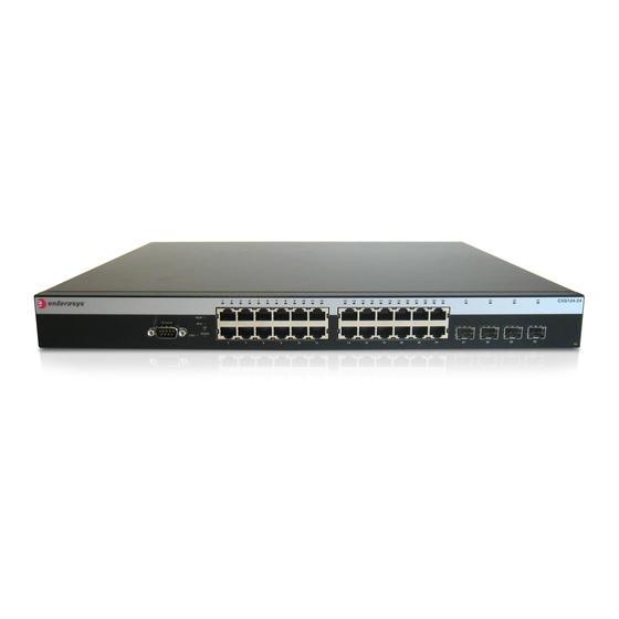
The following example adds a virtual switch configuration to a stack of C5 switches. The switch type being added is a C5G124-24 (SID 1), and it is being added as member unit 4. Port number 1 of the virtual switch (ge.4.1) is then configured in the same way that a physically present port would be configured. -
Page 44: Configuring Standalone A4 Stack Ports
Removing Units from an Existing Stack • Use clear ip address to remove the IP address of the stack. • Use clear license to remove an applied license from a switch. Configuration parameters and stacking information can also be cleared on the master unit only by selecting the “restore configuration to factory defaults”... -
Page 45: Chapter 3: Cli Basics
Using the Command Line Interface Configuring CLI Properties Switch Management Methods The Enterasys fixed switches can be managed using the following methods: • Locally using a VT type terminal or computer running a terminal emulation program connected to the switch’s console port. See... -
Page 46: Connecting Using The Console Port
Command Line Interface Enterasys Networks, Inc. 50 Minuteman Rd. Andover, MA 01810-1008 U.S.A. Phone: +1 978 684 1000 E-mail: support@enterasys.com WWW: http://www.enterasys.com (c) Copyright Enterasys Networks, Inc. 2012 Chassis Serial Number: 041800249041 Chassis Firmware Revision: x.xx.xx C5(su)-> 3-2 CLI Basics... -
Page 47: Logging In
Using the Command Line Interface Logging In By default, the switch is configured with three user login accounts—ro for Read-Only access, rw for Read-Write access, and admin for super-user access to all modifiable parameters. The default password is set to a blank string. For information on changing these default settings, refer to Chapter User Account and Password Management. -
Page 48: Cli Command Modes
Using the Command Line Interface commands without optional parameters, the defaults section lists “None”. For commands with optional parameters, this section describes how the CLI responds if the user opts to enter only the keywords of the command syntax. Figure 3-2 provides an example. -
Page 49: Displaying Scrolling Screens
Using the Command Line Interface Note: At the end of the lookup display, the system will repeat the command you entered without the Displaying Scrolling Screens If the CLI screen length has been set using the set length command, CLI output requiring more than one screen will display --More-- to indicate continuing screens. -
Page 50: Basic Line Editing Commands
Configuring CLI Properties Basic Line Editing Commands The CLI supports EMACs-like line editing commands. Table 3-1 lists some commonly used commands. Table 3-1 Basic Line Editing Commands Key Sequence Command Ctrl+A Move cursor to beginning of line. Ctrl+B Move cursor back one character. Ctrl+D Delete a character. -
Page 51: Example Cli Properties Configuration
Configuring CLI Properties Table 3-2 CLI Properties Configuration Commands (continued) Task Command Set the time (in minutes) an idle console or Telnet set logout timeout CLI session will remain connected before timing out. Refer to the CLI Reference for your switch model for more information about each command. Example CLI Properties Configuration In this example, the prompt is changed and a login banner is added. - Page 52 Configuring CLI Properties 3-8 CLI Basics...
-
Page 53: Factory Default Settings
MAC Address Settings 4-24 Configuring Node Aliases 4-26 Factory Default Settings The following tables list factory default settings available on the Enterasys fixed switches. Table 4-1 Default Settings for Basic Switch Operation Feature Default Setting Switch Mode Defaults CDP discovery protocol Auto enabled on all ports. -
Page 54: Factory Default Settings
Factory Default Settings Table 4-1 Default Settings for Basic Switch Operation (continued) Feature Default Setting Console (serial) port Baud rate: 9600 required settings Data bits: 8 Flow control: disabled Stop bits: 1 Parity: none DHCP server Disabled. Diffserv Disabled. (B3 platforms only) EAPOL Disabled. - Page 55 Factory Default Settings Table 4-1 Default Settings for Basic Switch Operation (continued) Feature Default Setting Password history No passwords are checked for duplication. Policy classification Classification rules are automatically enabled when created. Port auto-negotiation Enabled on all ports. Port advertised ability Maximum ability advertised on all ports.
-
Page 56: Default Settings For Router Operation
Factory Default Settings Table 4-1 Default Settings for Basic Switch Operation (continued) Feature Default Setting Spanning Tree topology Enabled. change trap suppression Spanning Tree version Set to mstp (Multiple Spanning Tree Protocol). Disabled. System baud rate Set to 9600 baud. System contact Set to empty string. -
Page 57: Initial Configuration Overview
Initial Configuration Overview Table 4-2 Default Settings for Router Operation (continued) Feature Default Setting Hello interval (OSPF) Set to 10 seconds for broadcast and point-to-point networks. Set to 30 seconds for non-broadcast networks. ICMP Enabled for echo-reply and mask-reply modes. IP-directed broadcasts Disabled. -
Page 58: Advanced Configuration Overview
Table 4-3 provides an overview of configuring the switch for each area. Note: Though it is possible to configure policy by using the CLI, Enterasys Networks recommends that you use NetSight instead. Table 4-3 Advanced Configuration Task Refer to ... - Page 59 Advanced Configuration Overview Table 4-3 Advanced Configuration (continued) Task Refer to ... Configure the Telnet client and server. (Telnet client is enabled by default.) “Telnet Overview” on Note: For security, you may wish to disable Telnet and only use SSH. page 4-23 Configure the Secure Shell V2 (SSHv2) client and server.
-
Page 60: Licensing Advanced Features
In order to enable certain advanced features on some of the Fixed Switching platforms, you must purchase and activate a license key. If you have purchased a license, follow the instructions on Licensed Product Entitlement ID sheet to obtain the license activation key from the Enterasys customer site. -
Page 61: Node-Locked Licensing
Therefore, you must know the serial number of the switch to be licensed when you activate the license on the Enterasys customer site, and also when you apply the license to the switch as described below. Each switch to be licensed must have its own license and key and all members of a stack must be licensed in order to support licensed features in a stack environment. -
Page 62: Applying Node-Locked Licenses In A Stack
Obtain valid license keys for all members of the stack from the Enterasys customer site. Activate one or more licenses on the stack. -
Page 63: Adding A New Member To A Licensed Stack
14" unit 1 Validating license on unit 1 License successfully validated and set on unit 1 C5(su)->set license advrouter "0001:C5L3-LIC:2:4a76f2c8:A: Enterasys Networks:A00E0C0973D9:150a9501:098749e9ec095844 d727a2db88a31514" unit 2 Validating license on unit 2 License successfully validated and set on unit 2 Adding a New Member to a Licensed Stack... -
Page 64: Unicast Polling Mode
SNTP Configuration Unicast Polling Mode When an SNTP client is operating in unicast mode, SNTP update requests are made directly to a server, configured using the set sntp server command. The client queries these configured SNTP servers at a fixed poll-interval configured using the set sntp poll-interval command. The order in which servers are queried is based on a precedence value optionally specified when you configure the server. -
Page 65: Sntp Defaults
SNTP Configuration Use the set sntp authentication key command to configure an authentication key instance. The SNTP authentication key is associated with an SNTP server using the set sntp server command. An authentication key has to be trusted to be used with an SNTP server. Use the set sntp trusted- key command to add an authentication key to the trusted key list. -
Page 66: Managing And Displaying Sntp
SNTP Configuration Procedure 4-2 Configuring SNTP (continued) Step Task Command(s) When operating in unicast mode, optionally set sntp poll-interval value change the poll interval between SNTP unicast requests. The poll interval is 2 to the power of value in seconds, where value can range from 6 to 10. When operating in unicast mode, optionally set sntp poll-retry retry change the number of poll retries to a unicast... -
Page 67: Sntp Configuration Example
SNTP Configuration Table 4-5 Managing and Displaying SNTP (continued) Task Command(s) To reset the poll interval between unicast SNTP requests clear sntp poll-interval to its default value: To reset the number of poll retries to a unicast SNTP clear sntp poll-retry server to its default value: To reset the SNTP poll timeout to its default value: clear sntp poll-timeout... -
Page 68: Dhcp Configuration
DHCP Configuration 192.168.10.10 Active DHCP Configuration Dynamic Host Configuration Protocol (DHCP) for IPv4 is a network layer protocol that implements automatic or manual assignment of IP addresses and other configuration information to client devices by servers. A DHCP server manages a user-configured pool of IP addresses from which it can make assignments upon client requests. -
Page 69: Ip Address Pools
DHCP Configuration IP Address Pools IP address pools must be configured for both automatic and manual IP address allocation by a DHCP server. Automatic IP Address Pools When configuring an IP address pool for dynamic IP address assignment, the only required steps are to name the pool and define the network number and mask for the pool using the set dhcp pool network command. -
Page 70: Dhcp Configuration On A Non-Routing System
DHCP Configuration DHCP Configuration on a Non-Routing System The following procedure provides basic DHCP server functionality when the DHCP pool is associated with the system’s host IP address. This procedure would typically be used when the system is NOT configured for routing. Refer to the CLI Reference for your platform for details about the commands listed below. - Page 71 DHCP Configuration Procedure 4-5 DHCP Server Configuration on a Routing System Step Task Command(s) Create a VLAN and add ports to the VLAN. Only set vlan create vlan-id DHCP clients associated with this VLAN will be set port vlan port-string vlan-id served IP addresses from the DHCP address pool associated with this routed interface (VLAN).
-
Page 72: Managing And Displaying Dhcp Server Parameters
DHCP Configuration C5(su)->router(Config)#exit C5(su)->router#exit C5(su)->router>exit C5(su)->set dhcp enable C5(su)->set dhcp pool autopool2 network 6.6.0.0 255.255.0.0 Managing and Displaying DHCP Server Parameters Table 4-6 lists additional DHCP server tasks. Refer to Table 4-7 on page 4-20 for default DHCP server settings. Table 4-6 Managing and Displaying DHCP Server Task Commands... -
Page 73: Configuring Dhcp Ip Address Pools
DHCP Configuration Table 4-7 Default DHCP Server Parameters Parameter Description Default Value Number of ping packets Specifies the number of ping packets the 2 packets DHCP server sends to an IP address before assigning the address to a requesting client Configuring DHCP IP Address Pools This section provides procedures for the basic configuration of automatic (dynamic) and manual (static) IP address pools, as well as a list of the commands to configure other optional pool... - Page 74 DHCP Configuration • The subnet of the IP address being issued should be on the same subnet as the ingress interface (that is, the subnet of the host IP address of the switch, or if routing interfaces are configured, the subnet of the routing interface). •...
-
Page 75: Configuring Additional Pool Parameters
By default, Telnet is enabled both inbound and outbound. Use the show telnet command to display whether Telnet is currently enabled or disabled. The Enterasys fixed switches allow a total of four inbound and / or outbound Telnet session to run simultaneously. -
Page 76: Configuring Telnet
SSH Overview Configuring Telnet Procedure 4-8 Configuring Telnet Step Task Command(s) Enable or disable Telnet services, inbound, set telnet {enable | disable} outbound, or all. [inbound | outbound | all] Inbound = Telnet to the switch from a remote device Outbound = Telnet to other devices from the switch Display Telnet status... -
Page 77: Limiting Mac Addresses To Specific Vlans
MAC Address Settings Aging time: 600 seconds Limiting MAC Addresses to Specific VLANs Use the set mac multicast command to define on what ports within a VLAN a multicast address can be dynamically learned on, or on what ports a frame with the specified MAC address can be flooded. -
Page 78: Configuring Node Aliases
Configuring Node Aliases Procedure 4-10 Configuring MAC Address Settings Step Task Command(s) Display the MAC addresses in the switch’s show mac [address mac-address] filtering database (FID). [fid fid] [port port-string] [type {other | learned | self | mgmt | mcast}] Display the current timeout period for aging show mac agetime learned MAC entries/... - Page 79 Configuring Node Aliases C5(su)->show nodealias config ge.1.1 Port Number Max Entries Used Entries Status ----------- ----------- ------------ ---------- ge.1.1 Enable The following command disables the node alias agent on port ge.1.8: C5(su)->set nodealias disable ge.1.8 Fixed Switch Configuration Guide 4-27...
- Page 80 Configuring Node Aliases 4-28 System Configuration...
-
Page 81: Chapter 5: User Account And Password Management
Passwords are created and changed with the set password command. User accounts are deleted with the clear system login command. The Enterasys Fixed Switch platforms support up to 16 user accounts. When creating a new or editing an existing login account, use the following syntax:... -
Page 82: Emergency Access User Account
User Account Overview • The start and end hour and minute time period for which access will be allowed for this user based upon 24 hour time. (Not applicable for super user accounts.) • The days of the week for which access will be allowed for this user. (Not applicable for super user accounts.) •... -
Page 83: Account Lockout
User Account Overview • The emergency access user is still subject to the system lockout interval even on the console port. Account Lockout User accounts can be locked out based on the number of failed login attempts or a period of inactivity. - Page 84 User Account Overview Procedure 5-2 on page 5-4 shows how a super-user creates a new super-user account and assigns it as the emergency access account. Refer to the CLI Reference for your platform for details about the commands listed below. Procedure 5-1 Creating a New Read-Write or Read-Only User Account Step Task...
- Page 85 User Account Overview Procedure 5-2 Configuring a New Super-User / Emergency Access User Account Step Task Command(s) Assign the new super-user account as the set system lockout emergency-access emergency access account. username Display the system lockout settings show system lockout Disable the default super-user account, admin set system login admin super-user disable...
-
Page 86: Password Management Overview
Password Management Overview guest read-only enabled 00:00 24:00 mon tue wed Password Management Overview Individual user account passwords are configured with the set password command. Configured passwords are transmitted and stored in a one-way encrypted form, using a FIPS 140-2 compliant algorithm. -
Page 87: Defaults
Password Management Overview – Special characters (default 0) The set of special characters recognized is: ! @ # $ % ^ & * () ? = [ ] \ ; ? , ./ `. • Whether the switch enforces aging of system passwords. –... -
Page 88: System Password Settings Configuration
Password Management Overview Table 5-1 User Account and Password Parameter Defaults by Security Mode (continued) Parameter Normal Mode Default C2 Mode Default Minimum number of characters in password Allow consecutively repeating characters in 2 characters password Aging of system passwords disabled 90 days Password required at time of new user account... -
Page 89: Password Reset Button Functionality
SNMP, for more information about SNMP. Use the set mgmt-auth-notify command to enable or disable notifications for the authentication notification types specified in the Enterasys Management Authentication Notification MIB. You can specifically enable or disable a single authentication notification type, multiple authentication notification types or all the authentication notification types. - Page 90 Management Authentication Notification MIB Functionality Refer to the CLI Reference for your platform for detailed information about the commands listed below in Procedure 5-4. Procedure 5-4 Configuring Management Authentication Notification MIB Settings Step Task Command(s) Display the current settings for the Management show mgmt-auth-notify Authentication Notification MIB.
-
Page 91: Chapter 6: Firmware Image And File Management
Firmware Image and File Management This chapter describes how to download and install a firmware image file and how to save and display the system configuration as well as manage files on the switch. For information about... Refer to page... Managing the Firmware Image Managing Switch Configuration and Files Managing the Firmware Image... -
Page 92: Downloading From A Tftp Or Sftp Server
To perform a TFTP or SFTP download: Download to your computer the latest firmware for the switch from the Enterasys web site Unzip/uncompress the firmware, and copy the firmware to the upload/download directory configured for your TFTP server. The firmware is available at this Enterasys location: https://extranet.enterasys.com/downloads... -
Page 93: Setting The Boot Firmware
Managing the Firmware Image Setting the Boot Firmware Use the show boot system command to display the image file currently configured to be loaded at startup. For example: A4(su)->show boot system Current system image to boot: a4-series_06.61.00.0026 Use the set boot system command to set the firmware image to be loaded at startup. You can choose to reset the system to use the new firmware image immediately, or you can choose to only specify the new image to be loaded the next time the switch is rebooted. -
Page 94: Setting Tftp Parameters
Managing Switch Configuration and Files Caution: If you do not follow the steps above, you may lose remote connectivity to the switch. Setting TFTP Parameters You can configure some of the settings used by the switch during data transfers using TFTP. Use the show tftp settings command to display current settings. -
Page 95: Using An I-Series Memory Card
Managing Switch Configuration and Files Using an I-Series Memory Card The I3H-4FX-MEM and I3H-6TX-MEM IOMs provide a memory card slot where a small, separately-purchased memory card (I3H-MEM) may be inserted. The memory card provides a removable, non-volatile means for storing the system configuration and IP address only, and may be used to move the system’s configuration to another switch. -
Page 96: Displaying The Configuration
Managing Switch Configuration and Files Displaying the Configuration Executing show config without any parameters will display all the non-default configuration settings. Using the all parameter will display all default and non-default configuration settings. To display non-default information about a particular section of the configuration, such as port or system configuration, use the name of the section (or facility) with the command. -
Page 97: Applying A Saved Configuration
Managing Switch Configuration and Files Images: ================================================================== Filename: b5-series_06.42.03.0001 Version: 06.42.03.0001 Size: 6856704 (bytes) Date: Tue Dec 14 14:12:21 2010 CheckSum: 043637a2fb61d8303273e16050308927 Compatibility: B5G124-24, B5G124-24P2, B5G124-48, B5G124-48P2, B5K125-24 B5K125-24P2, B5K125-48, B5K125-48P2 Filename: b5-series_06.61.01.0032 (Active) (Boot) Version: 06.61.01.0032 Size: 7314432 (bytes) Date: Fri Jan 6 11:20:00 2012... -
Page 98: Managing Files
Managing Switch Configuration and Files Managing Files Table 6-1 lists the tasks and commands used to manage files. Table 6-1 File Management Commands Task Command List all the files stored on the system, dir [filename] or only a specific file. Display the system configuration. -
Page 99: Chapter 7: Configuring System Power And Poe
Configuring System Power and PoE This chapter describes how to configure Redundant Power Supply mode on the C5 and G-Series switches, and how to configure Power over Ethernet (PoE) on platforms that support PoE. The information about Power over Ethernet (PoE) applies only to fixed switching platforms that provide PoE support. -
Page 100: Implementing Poe
If a power state occurs on a PD (for example, when a PD is powered up or unplugged) If insufficient power is available for an attached PD, the corresponding port LED on the Enterasys device turns amber. The LED also turns amber if a PoE fault occurs (for example, a short in the Ethernet cable). -
Page 101: When Manual Mode Is Configured
Power over Ethernet Overview balance of power available for PoE. When any change is made to the hardware configuration, power supply status, or redundancy mode, the firmware recalculates the power available for PoE. On the S-Series, N-Series, and K-Series switches, you can also manually configure the maximum percentage of PoE power available to the chassis as a percentage of the total installed PoE power with the set inlinepower available command. -
Page 102: Configuring Poe
• Standalone G-Series: Procedure 7-3 on page 7-7 Note: You must be logged on to the Enterasys device with read-write access rights to use the commands shown in the procedures in the following sections. 7-4 Configuring System Power and PoE... -
Page 103: Stackable A4, B3, And C3 Devices
If that fails, the device uses the proprietary capacitor-based detection method. • ieee — The Enterasys device uses only the IEEE 802.3af/at standards resistor-based detection method. Refer to the switch’s CLI Reference Guide for more information about each command. -
Page 104: Stackable B5 And C5 Devices
IEEE 802.3af/st standards resistor- based detection method. If that fails, the device uses the proprietary capacitor-based detection method. • ieee — The Enterasys device uses only the IEEE 802.3af/at standards resistor-based detection method. (Optional) Set the PoE management mode on a set inlinepower management {realtime | specified module. -
Page 105: G-Series Devices
Configuring PoE Procedure 7-2 PoE Configuration for Stackable B5 and C5 Devices (continued) Step Task Command(s) (Optional on C5 only) Set the power set system power {redundant | non- redundancy mode on the system if two power redundant} supplies are installed. •... - Page 106 IEEE 802.3af/at standards resistor- based detection method. If that fails, the device uses the proprietary capacitor-based detection method. • ieee — The Enterasys device uses only the IEEE 802.3af/at standards resistor-based detection method. (Optional) Set the power redundancy mode on set system power {redundant | non- the system if two power supplies are installed.
- Page 107 The sum of the wattage configured for each module cannot exceed the total power available for PoE on the Enterasys device. If a G-Series device is configured for non- redundant mode (set system power) and manual mode (set inlinepower mode) and a...
-
Page 108: Example Poe Configuration
150W, or some portion of the 150W to the PoE modules to power the attached PDs. G3(su)->set inlinepower assign 100 2 PoE Display Commands Table 7-3 lists PoE show commands for Enterasys devices. Table 7-3 PoE Show Commands Task Command... -
Page 109: Chapter 8: Port Configuration
8-12 Port Configuration Overview The Enterasys stackable and standalone switches have fixed front panel switch ports. The I-Series and G-Series standalone switches also have expansion slots where optional I/O modules can be installed. Refer to the data sheet and/or the Installation Guide for the standalone switches for information about available optional I/O modules. -
Page 110: Examples
*.*.* Console Port Settings Each Enterasys switch includes a console port through which local management of the switch can be accessed using a PC, terminal, or modem. When switches are stacked, only the console port on the master unit is active. The console ports on the member units of the stack are deactivated. -
Page 111: Vt100 Terminal Mode
Port Configuration Overview C5(su)->show console vt100 terminal mode disabled Baud Flow Bits StopBits Parity ------ ------- ---- ---------- ------ 9600 Disable 8 none Use the set console baud command to change the baud rate of the console port. For example, to set the console port baud rate to 19200: C5(su)->set console baud 19200 VT100 Terminal Mode... -
Page 112: Auto-Negotiation And Advertised Ability
Port Configuration Overview Auto-Negotiation and Advertised Ability Auto-negotiation is an Ethernet feature that facilitates the selection of port speed, duplex, and flow control between the two members of a link, by first sharing these capabilities and then selecting the fastest transmission mode that both ends of the link support. Auto-negotiation is enabled by default. -
Page 113: Port Flow Control
Port Configuration Overview By default, Enterasys switch devices are configured to automatically detect the cable type connection, straight through (MDI) or cross-over (MDIX), required by the cable connected to the port. You can configure ports to only use MDI or MDIX connections with the set port mdix command. -
Page 114: Protected Port Mode
Port Configuration Overview maximum number of packets which can be received per second with the set port broadcast command: Maximum packet per second values are: • 148810 for Fast Ethernet ports • 1488100 for 1-Gigabit ports. • 14881000 for 10- Gigabit ports Use the show port broadcast command to display current threshold settings. -
Page 115: Displaying Cable Status
Port Configuration Overview Table 8-1 Displaying Port Status Task Command Display whether or not one or more ports are enabled for show port [port-string] switching. Display operating and admin status, speed, duplex mode show port status [port-string] and port type for one or more ports on the device. Display port counter statistics detailing traffic through the show port counters [port-string] [switch | device and through all MIB2 network devices. -
Page 116: Example
Link flapping indicates a Layer 1 (physical layer) problem, such as a faulty cable or GBIC. If link flapping occurs, your Enterasys switch can react by disabling the affected port and generating a syslog entry and an SNMP trap to notify you of the event. -
Page 117: Basic Link Flap Detection Configuration
You can enable link flap detection globally on your Enterasys switch or on specific ports, such as uplink ports. The link flap detection feature allows you to specify the action that occurs when a certain number of link flapping instances occur within a certain period of time. -
Page 118: Example
If the link flap threshold is exceeded within the link flap interval (eight link flap conditions within 20 seconds, as configured above), the Enterasys device will, by default, disable the port (for 600 seconds, as configured above) and generate both a syslog entry and an SNMP trap. These default actions can be changed by using the set linkflap action command. -
Page 119: Link Flap Detection Display Commands
Transmit Queue Monitoring If no additional power losses occur on the PoE devices and no additional link flapping conditions occur, the network administrator disables link flap detection on the PoE ports. C5(rw)->set linkflap portstate disable ge.1.1-12 Link Flap Detection Display Commands Table 8-3 lists link flap detection show commands. -
Page 120: Port Mirroring
Port Mirroring Table 8-4 Transmit Queue Monitoring Tasks Task Command Configure the time interval, in seconds, that ports set txqmonitor downtime seconds disabled by the transmit queue monitoring feature remain disabled. The default value is 0, meaning that disabled ports will remain disabled until cleared manually or until their next link state transition. -
Page 121: Configuring Port Mirroring
Port Mirroring • LAG ports can be a mirror source port, but not a mirror destination port. If a LAG port is a mirror source port, no other ports can be configured as source ports. • Both transmit and receive traffic will be mirrored. •... -
Page 122: Configuring Remote Port Mirroring
Port Mirroring Remote port mirroring is an extension to port mirroring which facilitates simultaneous mirroring of multiple source ports on multiple switches across a network to one or more remote destination ports. Remote port mirroring involves configuration of the following port mirroring related parameters: Configuration of normal port mirroring source ports and one destination port on all switches, as described above. -
Page 123: Configuring Smon Mib Port Mirroring
Port Mirroring Configuring SMON MIB Port Mirroring SMON port mirroring support allows you to redirect traffic on ports remotely using SMON MIBs. This is useful for troubleshooting or problem solving when network management through the console port, telnet, or SSH is not feasible. Procedures Perform the following steps to configure and monitor port mirroring using SMON MIB objects. - Page 124 Port Mirroring Enter MIB option 6 (destroy) and perform an SNMP Set operation. (Optional) Use the CLI to verify the port mirroring instance has been deleted as shown in the following example: C5(su)->show port mirroring No Port Mirrors configured. 8-16 Port Configuration...
-
Page 125: Vlan Overview
Configuring VLANs This chapter describes how to configure VLANs on Enterasys fixed stackable and standalone switches. For information about... Refer to page... VLAN Overview Implementing VLANs Understanding How VLANs Operate VLAN Support on Enterasys Switches Configuring VLANs Terms and Definitions... -
Page 126: Implementing Vlans
By default, all Enterasys switches run in 802.1Q VLAN operational mode. All ports on all Enterasys switches are assigned to a default VLAN (VLAN ID 1), which is enabled to operate and assigns all ports an egress status of untagged. This means that all ports will be allowed to transmit frames from the switch without a VLAN tag in their header. -
Page 127: Preparing For Vlan Configuration
(such as servers) with NICs that share a common MAC address. One FID is assigned per VLAN. The FID value is the same as the VID it is assigned to. This is the default mode on Enterasys switches. Fixed Switch Configuration Guide 9-3... -
Page 128: Vlan Assignment And Forwarding
VLAN Assignment and Forwarding Receiving Frames from VLAN Ports By default, Enterasys switches run in 802.1Q operational mode, which means that every frame received by the switch must belong to, or be assigned to, a VLAN. The type of frame under consideration and the filter setting of the switch determines how it forwards VLAN frames. -
Page 129: Forwarding Decisions
Understanding How VLANs Operate Forwarding Decisions VLAN forwarding decisions for transmitting frames is determined by whether or not the traffic being classified is or is not in the VLAN’s forwarding database as follows: • Unlearned traffic: When a frame’s destination MAC address is not in the VLAN’s forwarding database (FDB), it will be forwarded out of every port on the VLAN’s egress list with the frame format that is specified. -
Page 130: Vlan Support On Enterasys Switches
• VID 4095 is reserved by IEEE for implementation use. Notes: Each VLAN ID in a network must be unique. If you enter a duplicate VLAN ID, the Enterasys switch assumes you intend to modify the existing VLAN. VLAN Types Enterasys switches support traffic classification for the following VLAN types. -
Page 131: Policy-Based Vlans
VLANs that currently have active members. By default, GVRP is globally enabled but disabled at the port level on all Enterasys devices except the N-Series. On the N-Series, GVRP is enabled globally and at the port level. To allow GVRP to... -
Page 132: Configuring Vlans
Configuring VLANs Figure 9-3 Example of VLAN Propagation Using GVRP Note: If a port is set to “forbidden” for the egress list of a VLAN, then the VLAN’s egress list will not be dynamically updated with that port. Administratively configuring a VLAN on an 802.1Q switch creates a static VLAN entry that will always remain registered and will not time out. -
Page 133: Default Settings
Configuring VLANs Default Settings Table 9-1 lists VLAN parameters and their default values. Table 9-1 Default VLAN Parameters Parameter Description Default Value garp timers Configures the three GARP timers. • Join timer: 20 centiseconds The setting is critical and should only •... - Page 134 Configuring VLANs Procedure 9-1 Static VLAN Configuration (continued) Step Task Command(s) Assign switch ports to the VLAN. set port vlan port-string vlan-id This sets the port VLAN ID (PVID). The PVID [modify-egress | no-modify-egress] determines the VLAN to which all untagged frames received on the port will be classified.
-
Page 135: Example Configuration
C5(su)->set port discard ge.1.2-4 tagged Creating a Secure Management VLAN If you are configuring an Enterasys device for multiple VLANs, it may be desirable to configure a management-only VLAN. This allows a station connected to the management VLAN to manage... -
Page 136: Configuring Dynamic Vlans
Configuring VLANs the device. It also makes management secure by preventing configuration through ports assigned to other VLANs. Procedure 9-2 provides an example of how to create a secure management VLAN. This example, which sets the new VLAN as VLAN 2, assumes the management station is attached to ge.1.1, and wants untagged frames. -
Page 137: Configuring Protocol-Based Vlan Classification
Configuring VLANs Procedure 9-3 Dynamic VLAN Configuration (continued) Step Task Command(s) Optionally, set the GARP join, leave, and set garp timer {[join timer-value] leaveall timer values. Each timer value is in [leave timer-value] centiseconds. [leaveall timer-value]} port-string Caution: The setting of GARP timers is critical and should only be changed by personnel familiar with 802.1Q standards. -
Page 138: Monitoring Vlans
Terms and Definitions Ports 1 through 5 on the switch unit 4 are configured as egress ports for the VLANs while ports 8 through 10 on the switch unit 5 are configured as ingress ports that will do the policy classification. - Page 139 Terms and Definitions Table 9-3 VLAN Terms and Definitions (continued) Term Definition Forwarding List A list of the ports on a particular device that are eligible to transmit frames for a selected VLAN. GARP Multicast A GARP application that functions in a similar fashion as GVRP, except that GMRP Registration registers multicast addresses on ports to control the flooding of multicast frames.
- Page 140 Terms and Definitions 9-16 Configuring VLANs...
-
Page 141: Chapter 10: Configuring User Authentication
(supplicant) attempting to gain access to the network. Enterasys authentication uses the RADIUS protocol to control access to switch ports from an authentication server and to manage the message exchange between the authenticating device and the server. -
Page 142: Implementing User Authentication
X-509 certificate using a TLS tunnel, after which the client authentication credentials are exchanged. All Enterasys platforms support IEEE 802.1x, which protects against unauthorized access to a network, DoS attacks, theft of services and defacement of corporate web pages. -
Page 143: Port Web Authentication (Pwa)
User Authentication Overview devices that do not support 802.1x or web authentication. Since MAC-based authentication authenticates the device, not the user, and is subject to MAC address spoofing attacks, it should not be considered a secure authentication method. However, it does provide a level of authentication for a device where otherwise none would be possible. - Page 144 User Authentication Overview Multi-User Authentication Multi-user authentication provides for the per-user or per-device provisioning of network resources when authenticating. It supports the ability to receive from the authentication server: • A policy traffic profile, based on the user account’s RADIUS Filter-ID configuration •...
-
Page 145: Applying Policy To Multiple Users On A Single Port
User Authentication Overview Figure 10-1 Applying Policy to Multiple Users on a Single Port Authentication Request Switch Authentication Response Radius Server User 1 SMAC 00-00-00-11-11-11 Authentication Credentials User 1 Authentication Credentials User 2 Authentication Request Authentication Credentials User 3 Authentication Dynamic Admin Rule User1 Filter ID -->... -
Page 146: Authenticating Multiple Users With Different Methods On A Single Port
User Authentication Overview credentials sent to the RADIUS server. RADIUS looks up the user account for that user based upon the SMAC. The Filter-ID for that user is returned to the switch in the authentication response, and the authentication is validated for that user. Figure 10-2 Authenticating Multiple Users With Different Methods on a Single Port Authentication... -
Page 147: Remote Authentication Dial-In Service (Radius)
User Authentication Overview Figure 10-3 Selecting Authentication Method When Multiple Methods are Validated SMAC=User 2 SMAC=User 1 SMAC=User 3 Switch MultiAuth Sessions Auth. Agent <User 1, 802.1x, Authenticated, PID=Credit, Applied> 802.1X Credit Policy Role <User 2, PWA, Authenticated, PID=Sales, Applied> <User 1, PWA, Authenticated, PID=Credit, Applied>... -
Page 148: How Radius Data Is Used
Accept or Reject message back to the switch. How RADIUS Data Is Used The Enterasys switch bases its decision to open the port and apply a policy or close the port based on the RADIUS message, the port's default policy, and unauthenticated behavior configuration. - Page 149 When disabled per port or globally, the device will not process Tunnel attributes. By default, all policy-capable Enterasys platforms will dynamically assign a policy profile to the port of an authenticating user based on the receipt of the Filter-ID RADIUS attribute. This is not the case for RADIUS tunnel attributes in that, by default, VLAN authorization is disabled.
-
Page 150: Policy Maptable Response
User Authentication Overview • Value: Indicates the type of tunnel. A value of 0x06 indicates that the tunneling medium pertains to 802 media (including Ethernet) Tunnel-Private-Group-ID attribute indicates the group ID for a particular tunneled session. Set the Tunnel-Private-Group-ID attribute parameters as follows: •... - Page 151 User Authentication Overview When the maptable response is set to tunnel mode, the system will use the tunnel attributes in the RADIUS reply to apply a VLAN to the authenticating user and will ignore any Filter-ID attributes in the RADIUS reply. When tunnel mode is configured, VLAN-to-policy mapping will not occur on a stackable fixed switch or standalone fixed switch platform.
-
Page 152: Configuring Authentication
Configuring Authentication If VLAN authorization is not enabled, the tunnel attributes are ignored. When Policy Maptable Response is “Profile” When the switch is configured to use only Filter-ID attributes, by setting the set policy maptable command response parameter to policy: •... - Page 153 Configuring Authentication Table 10-1 Default Authentication Parameters (continued) Parameter Description Default Value macauthentication Globally enables or disables MAC Disabled. authentication on a device. macauthentication port Enables or disables MAC Disabled. authentication on a port MultiAuth idle-timeout Specifies the period length for which 300 seconds.
-
Page 154: Configuring Ieee 802.1X
Configuring Authentication Table 10-1 Default Authentication Parameters (continued) Parameter Description Default Value realm Specifies authentication server Both: management-access and configuration scope. network-access. VLAN authorization Enables or disables globally and per Globally: Disabled. status port VLAN authorization. Per Port: Enabled. VLAN authorization Determines whether dynamic VLAN Untagged. -
Page 155: Configuring Mac-Based Authentication
Configuring Authentication Procedure 10-1 IEEE 802.1x Configuration (continued) Step Task Command(s) Display the access entity index values. Ports show dot1x auth-session-stats used to authenticate and authorize supplicants utilize access entities that maintain entity state, counters, and statistics for an individual supplicant. -
Page 156: Configuring Port Web Authentication (Pwa)
Configuring Authentication Procedure 10-2 MAC-Based Authentication Configuration (continued) Step Task Command(s) Enable or disable MAC authentication globally set macauthentication {enable | disable} on the device. By default, MAC authentication is globally disabled on the device. Set the MultiAuth mode. set multiauth mode multi Display MAC authentication configuration or show macauthentication status of active sessions. -
Page 157: Optionally Enable Guest Network Privileges
Configuring Authentication Optionally Enable Guest Network Privileges With PWA enhanced mode enabled, you can optionally configure guest networking privileges. Guest networking allows an administrator to specify a set of credentials that will, by default, appear on the PWA login page of an end station when a user attempts to access the network. When enhanced mode is enabled, PWA will use a guest password and guest user name to grant network access with default policy privileges to users without established login names and passwords. -
Page 158: Setting Multiauth Authentication Precedence
Configuring Authentication Procedure 10-4 MultiAuth Authentication Configuration Step Task Command(s) For a single user, single authentication 802.1x set multiauth mode strict port configuration, set MultiAuth mode to strict. For multiple user 802.1x authentication or any set multiauth mode multi non-802.1x authentication, set the system authentication mode to use multiple authenticators simultaneously. -
Page 159: Setting Multiauth Authentication Timers
Configuring Authentication • Authentication Required – Authentication methods are active on the port, based on the global and per port authentication method configured. Before authentication succeeds, no traffic is forwarded onto the network. After authentication succeeds, the user or device gains access to the network based upon the policy information returned by the authentication server in the form of the RADIUS Filter-ID attribute, or the static configuration on the switch. -
Page 160: Displaying Multiauth Configuration Information
Configuring Authentication Procedure 10-7 MultiAuth Authentication Timers Configuration Step Task Command(s) Optionally set the MultiAuth authentication idle set multiauth idle-timeout auth-method timeout value for the specified authentication timeout method. Reset the MultiAuth authentication idle timeout clear multiauth idle-timeout auth-method value to its default value for the specified authentication method. -
Page 161: Configuring Radius
Configuring Authentication • dynamic – Egress formatting will be based upon information contained in the authentication response. The VLAN authorization table will always list any tunnel attribute’s VIDs that have been received for authenticated end systems, but a VID will not actually be assigned unless VLAN authorization is enabled both globally and on the authenticating port. -
Page 162: Configuring User + Ip Phone Authentication
Configuring Authentication • Server identification provides for the configuration of the server IP address and index value. The index determines the order in which the switch will attempt to establish a session with an authentication server. After setting the index and IP address you are prompted to enter a secret value for this authentication server. -
Page 163: Example
Configuring Authentication Note: User + IP Phone authentication is not supported on the I-Series With “User + IP Phone” authentication, the policy role for the IP phone is statically mapped using a policy admin rule which assigns any frames received with a VLAN tag set to a specific VID (for example, Voice VLAN) to a specified policy role (for example, IP Phone policy role). - Page 164 Configuring Authentication The following code example: • Creates and names two VLANS, one for the users and one for the phones. • Creates a CoS setting of index 55. • Sets the number of users to 2 on all the user ports. •...
-
Page 165: Authentication Configuration Example
Authentication Configuration Example Authentication Configuration Example Our example covers the three supported stackable and fixed switch authentication types being used in an engineering group: end-user stations, an IP phone, a printer cluster, and public internet access. Figure 10-4 provides an overview of the fixed switch authentication configuration. Figure 10-4 Stackable Fixed Switch Authentication Configuration Example Overview Engineering end-user stations... -
Page 166: Configuring Multiauth Authentication
Authentication Configuration Example Configuring MultiAuth Authentication MultiAuth authentication must be set to multi whenever multiple users of 802.1x need to be authenticated or whenever any MAC-based or PWA authentication is present. For ports where no authentication is present, such as switch to switch, or switch to router connections, you should also set MultiAuth port mode to force authenticate to assure that traffic is not blocked by a failed authentication. -
Page 167: Configuring The Printer Cluster For Mac-Based Authentication
CoS and rate limit. • Enable MAC authentication globally on the switch. • Enter the MAC authentication password as enterasys on the switch. • Set the MAC authentication significant-bits to 24. • Enable MAC authentication on the ports used by the printer cluster: ge.1.3-4... -
Page 168: Configuring The Public Area Pwa Station
Once the policy and RADIUS account are configured, enter the following CLI input on the switch: System(rw)->set pwa enable System(rw)->set pwa ipaddress 10.10.10.101 System(rw)->set pwa banner ”Enterasys Networks Public Internet Access Station” System(rw)->set pwa enhancedmode enable System(rw)->set pwa guestatus authradius System(rw)->set pwa guestname guest... - Page 169 (PWA) RADIUS Filter-ID An Enterasys proprietary string formatted in the RADIUS Access-Accept packet sent back from the authentication server to the switch containing either the policy to apply to the supplicant, the management type for the port, or both.
- Page 170 Terms and Definitions 10-30 Configuring User Authentication...
-
Page 171: Chapter 11: Configuring Link Aggregation
Configuring Link Aggregation This chapter describes how to configure link aggregation on the fixed switch platforms. For information about... Refer to page... Link Aggregation Overview 11-1 Configuring Link Aggregation 11-9 Link Aggregation Configuration Example 11-11 Terms and Definitions 11-15 Link Aggregation Overview IEEE 802.3ad link aggregation provides a standardized means of grouping multiple parallel Ethernet interfaces into a single logical Layer 2 link. -
Page 172: Implementing Link Aggregation
Link Aggregation Overview problems if they also wanted, or needed, to use a different brand of networking hardware. Link aggregation is standards based allowing for interoperability between multiple vendors in the network. Older implementations required manual configuration. With LACP, if a set of links can aggregate, they will aggregate. -
Page 173: How A Lag Forms
Link Aggregation Overview Note: A given link is allocated to, at most, one LAG at a time. The allocation mechanism attempts to maximize aggregation, subject to management controls. • Attaches the port to the aggregator used by the LAG, and detaches the port from the aggregator when it is no longer used by the LAG. -
Page 174: Lag Formation
Link Aggregation Overview Figure 11-1 LAG Formation PARTNER Device Port Admin Speed 100M 100M 100M ACTOR Device Admin Port Speed LAG 1 100M 100M 100M LAG 2 100M Device 100M 100M 100M 100M 100M 100M Actor ports 1 - 3 on device A directly connect to partner ports 1 - 3 on device B: •... -
Page 175: Attached Ports
Link Aggregation Overview • Investigating port admin keys, we see that ports 4 - 6 on device A are set to 100 (the same setting as all LAG ports on the device), while ports 7 and 8 on device A are set to 300 and 400, respectively. -
Page 176: Lags Moved To Attached State
Link Aggregation Overview Because port 6 has both a different speed and a higher priority than the port with the lowest priority in the LAG, it is not moved to the attached state. If LAG members with different port speeds should tie for the lowest port priority, the LAG member with the lowest port number breaks the tie. -
Page 177: Single Port Attached State Rules
Link Aggregation Overview Single Port Attached State Rules By default, a LAG must contain two or more actor and partner port pairs for the LAG to be initiated by this device. A feature exists to allow the creation of a single port LAG that is disabled by default. -
Page 178: Static Port Assignment
• lacpexpire - Transition to expired state is allowed. It is recommended that these default states not be changed unless you know what you are doing. Contact Enterasys customer support should you need assistance modifying port level administrative states. Partner Default A default partner system ID can be set. -
Page 179: Configuring Link Aggregation
Configuring Link Aggregation The virtual link aggregation ports continue to be designated as lag.0.x, where x can range from 1 to 24, depending on the maximum number of LAGs configured. Configuring Link Aggregation This section provides details for the configuration of link aggregation on the N-Series, S-Series, stackable, and standalone switch products. -
Page 180: Managing Link Aggregation
Configuring Link Aggregation Procedure 11-1 Configuring Link Aggregation (continued) Step Task Command(s) Optionally, change the administratively assigned set lacp aadminkey port-string value key for each aggregation on the device. Optionally, enable single port LAGs on the set lacp singleportlag {enable | disable} device. -
Page 181: Link Aggregation Configuration Example
Link Aggregation Configuration Example Table 11-4 Managing Link Aggregation (continued) Task Command Reset the maximum number of LACP clear lacp groups groups to the default of 6. If the number of LACP groups has been changed from the default, executing this command will result in a system reset and LACP configuration settings will be returned to their default values, including the group limit. -
Page 182: Link Aggregation Example
Link Aggregation Configuration Example on each device is to ensure that LAGs form only where we configure them. Since the admin key for the LAG and its associated ports must agree for the LAG to form, an easy way to ensure that LAGs do not automatically form is to set the admin key for all LAGS on all devices to a non- default value. -
Page 183: Lag And Physical Port Admin Key Assignments
Link Aggregation Configuration Example Table 11-6 LAG and Physical Port Admin Key Assignments Physical Port Device LAG Admin Key Physical Port Admin Key S8 Distribution Switch ge.1.1 ge.2.1 ge.3.1 ge.4.1 ge.1.2 ge.2.2 ge.3.2 ge.4.2 Fixed Switch Stack 1 ge.1.21 ge.1.22 ge.2.23 ge.3.24 Fixed Switch Stack 2... -
Page 184: Configuring The S8 Distribution Switch
Link Aggregation Configuration Example The output algorithm defaults to selecting the output port based upon the destination and source IP address. This setting will not be changed in our example. In any case, note that the stackable switch does not support the output algorithm feature. Configuring the S8 Distribution Switch The first thing we want to do is set the admin key for all LAGs to the non-default value of 65535 so that no LAGs will automatically form:... -
Page 185: Configuring The Server
Terms and Definitions LACP port state is disabled by default on the B5s and C5s, so we will enable LACP port state here. We next want to set the admin keys for the stackable switch physical ports: Stack2(rw)->set port lacp port ge.1.21 aadminkey 200 enable Stack2(rw)->set port lacp port ge.1.22 aadminkey 200 enable Stack2(rw)->set port lacp port ge.1.23 aadminkey 200 enable Stack2(rw)->set port lacp port ge.1.24 aadminkey 200 enable... - Page 186 Terms and Definitions Table 11-7 Link Aggregation Configuration Terms and Definitions (continued) Term Definition Port Priority Port priority determines which physical ports are moved to the attached state when physical ports of differing speeds form a LAG. Port priority also determines which ports will join a LAG when the number of supported ports for a LAG is exceeded.
-
Page 187: Chapter 12: Configuring Snmp
Configuring SNMP This chapter describes basic SNMP concepts, the SNMP support provided on Enterasys fixed stackable and standalone switches, and how to configure SNMP on the switches using CLI commands. For information about... Refer to page... SNMP Overview 12-1 SNMP Concepts... -
Page 188: Snmp Concepts
SNMP provides a message format for communication between managers and agents, which use a MIB and a relatively small set of commands to exchange information. The SNMP manager can be ® part of a network management system, such as Enterasys NetSight , while the agent and MIB reside on the switch. -
Page 189: Trap Versus Inform Messages
Levels” on page 12-6 for more information. SNMP Support on Enterasys Switches By default, SNMP Version 1 (SNMPv1) is configured on Enterasys switches. The default configuration includes a single community name - public - which grants read-write access to the whole MIB tree for both SNMPv1 and SNMPv2c. -
Page 190: Versions Supported
SNMPv3 is fully described in RFC 2571, RFC 2572, RFC 2573, RFC 2574, and RFC 2575. SNMPv1 andv2c Network Management Components The Enterasys implementation of SNMPv1 and v2c network management components fall into the following three categories: •... -
Page 191: Terms And Definitions
SNMP Support on Enterasys Switches Terms and Definitions Table 12-2 lists common SNMP terms and defines their use on Enterasys devices. Table 12-2 SNMP Terms and Definitions Term Definition community A name string used to authenticate SNMPv1 and v2c users. -
Page 192: Security Models And Levels
An SNMP security model is an authentication strategy that is set up for a user and the group in which the user resides. A security level is the permitted level of security within a security model. The three levels of SNMP security on Enterasys devices are: No authentication required (NoAuthNoPriv); authentication required (AuthNoPriv); and privacy (authPriv). A combination of a security model and a security level determines which security mechanism is employed when handling an SNMP frame. -
Page 193: Configuring Snmp
12-15 Configuration Basics Completing an SNMP configuration on an Enterasys device involves defining users who will be authorized to receive SNMP notifications about network events, associating security (target) parameters, access rights and MIB views to those users, and specifying an IP address where they will receive notifications. -
Page 194: Snmp Defaults
Modifying the Default Configuration” on page 12-10. To take advantage of the advanced security and other features available in SNMPv3, it is recommended that you add to the Enterasys default configuration by configuring SNMPv3 as described in “Configuring SNMPv3” on page 12-10. -
Page 195: Configuring Snmpv1/Snmpv2C
TVTrapTag. enterasys(su)->set snmp community public enterasys(su)->set snmp group groupRW user public security model v1 enterasys(su)->set snmp access groupRW security-model v1 read RW write RW notify RW enterasys(su)->set snmp view viewname RW subtree 1... -
Page 196: Adding To Or Modifying The Default Configuration
TVTrap tag TVTrapTag Adding to or Modifying the Default Configuration By default, SNMPv1 is configured on Enterasys switches. A single community name - public - is configured, which grants read-write access to the whole MIB tree for both SNMPv1 and SNMPv2c. - Page 197 Configuring SNMP Procedure 12-2 SNMPv3 Configuration Step Task Command(s) Create an SNMPv3 user and specify set snmp user user [remote remoteid] authentication, encryption, and security [privacy privpassword] credentials. [authentication {md5 | sha}] [authpassword] • If remote is not specified, the user will be registered for the local SNMP engine.
- Page 198 Create the user Enterasys_user, specifying authentication, encryption, and security credentials. • Assign Enterasys_user to the Enterasys group and associate it to the SNMPv3 security model, usm. • Specify that, if SNMP messages are received with authentication and encryption, the view, readView for read requests, and the view writeView for write requests will be applied to this user group based on the USM security model.
-
Page 199: Configuring An Snmpv3 Inform Or Trap Engine Id
EngineID on the sender as shown in the example in Procedure 12-3. This example assumes that NetSight Console is the receiver, and an Enterasys switch is the sender. Note: The following file location and EngineID are provided as examples. Your settings will vary. Procedure 12-3 adds to the configuration example shown in “Configuring an SNMPv3 Inform or... -
Page 200: Configuring An Snmp View
Configuring SNMP Procedure 12-3 Configuring an EngineID (continued) Step Task Command(s) On the Enterasys switch, define the same user set snmp user v3user remote as in the above example (v3user) with this 800007e5804f190000d232aa40 privacy EngineID and with the same Auth/Priv despasswd authentication md5 passwords you used previously. -
Page 201: Configuring Secure Snmp Community Names
CLI login passwords, and SNMP security names. Enterasys recommends that you “secure” all SNMP community names. You do this by creating a configuration that hides, through the use of “views” sensitive information from SNMP v1/v2c... - Page 202 Configuring SNMP Procedure 12-4 Configuring Secure Community Names Step Task Command(s) Create the following SNMP view group set snmp access admin-groupname configurations. security-model usm privacy exact read secured-viewname write secure- • An admin (v3) view group with secure read, viewname notify secured-viewname write, and notify access set snmp access read-only-groupname •...
-
Page 203: Example
The following example shows an SNMP community names configuration using the steps in Procedure 12-4 on page 12-16. enterasys(su)->set snmp access gAdmin security-model usm privacy exact read vSecured write vSecured notify vSecured enterasys(su)->set snmp access gReadOnlyV1V2C security-model v1 exact read vUnsecured enterasys(su)->set snmp access gReadOnlyV1V2C security-model v2c... -
Page 204: Reviewing Snmp Settings
Reviewing SNMP Settings Reviewing SNMP Settings Table 12-5 Commands to Review SNMP Settings Task Command Display SNMPv1/SNMPv2c community names and show snmp community name status. Display the context list configuration for SNMP view- show snmp context based access control. Display SNMP traffic counter values. show snmp counters Display SNMP engine properties. -
Page 205: Chapter 13: Configuring Neighbor Discovery
Configuring Neighbor Discovery This chapter describes how to configure the Link Layer Discovery Protocol (LLDP), the Enterasys Discovery Protocol, and the Cisco Discovery Protocol on Enterasys fixed stackable and standalone switches. For information about... Refer to page... Neighbor Discovery Overview... - Page 206 Neighbor Discovery Overview connected neighbors. While Enterasys Discovery Protocol and Cisco Discovery Protocol are vendor-specific protocols, LLDP is an industry standard (IEEE 802.1AB), vendor-neutral protocol. The LLDP-enabled device periodically advertises information about itself (such as management address, capabilities, media-specific configuration information) in an LLDPDU (Link Layer Discovery Protocol Data Unit), which is sent in a single 802.3 Ethernet frame (see...
-
Page 207: Communication Between Lldp-Enabled Devices
Neighbor Discovery Overview Figure 13-1 Communication between LLDP-enabled Devices Discovery MIB Discovery MIB Port Device Info Port Device Info ge. 1.1 IP phone x.x.x.x ge. 1.1 IP switch x.x.x.x ge. 1.2 x.x.x.x ge. 1.2 IP phone x.x.x.x ge. 1.4 IP switch x.x.x.x ge. - Page 208 Neighbor Discovery Overview There are two primary LLDP-MED device types (as shown in Figure 13-2 on page 13-5): • Network connectivity devices, which are LAN access devices such as LAN switch/routers, bridges, repeaters, wireless access points, or any device that supports the IEEE 802.1AB and MED extensions defined by the standard and can relay IEEE 802 frames via any method.
-
Page 209: Lldpdu Frames
Neighbor Discovery Overview Figure 13-2 LLDP-MED LLDP-MED Network Connectivity Devices: Provide IEEE 802 network access to LLDP-MED endpoints (for example, L2/L3 switch) LLDP-MED Generic Endpoints (Class I): Basic participant endpoints in LLDP-MED (for example, IP communications controller) IP Network Infrastructure (IEEE 802 LAN) LLDP-MED Media Endpoints (Class ll): Supports IP media streams... - Page 210 Neighbor Discovery Overview Figure 13-3 Frame Format IEEE 802.3 LLDP frame format LLDP Data + pad Ethertype LLDP_Multicast 88-CC LLDPDU address address 6 octets 6 octets 2 octets 1500 octets 4 octets LLDPDU format Chassis ID TLV Time to Live End of LLDPDU Port ID TLV (M) Optional TLV...
-
Page 211: Configuring Lldp
Some TLVs support multiple subtypes. For example, Port ID is sent as an ifName (for example, ge.1.1) between Enterasys devices, but when an LLDP-MED endpoint is detected on a port, that TLV subtype changes to a network address (MAC address), and other MED TLVs are sent, as defined by the MED spec. - Page 212 Configuring LLDP Table 13-1 LLDP Configuration Commands (continued) Task Command Enable or disable transmitting and processing set lldp port status {tx-enable | rx- received LLDPDUs on a port or range of ports. enable | both | disable} port-string Enable or disable sending LLDP traps when a set lldp port trap {enable | disable} remote system change is detected.
-
Page 213: Basic Lldp Configuration
[med-poe]} port-string Refer to your device’s CLI Reference Guide for more information about each command. Basic LLDP Configuration Procedure 13-1 describes the basic steps to configure LLDP on all Enterasys switch devices. Procedure 13-1 Configuring LLDP Step Task Command(s) Configure global system LLDP parameters. -
Page 214: Lldp Display Commands
Set the message interval frequency (in seconds) of set cdp interval frequency the Enterasys Discovery Protocol. Set the hold time value for Enterasys Discovery set cdp hold-time hold-time Protocol configuration messages. 13-10 Configuring Neighbor Discovery... -
Page 215: Example Enterasys Discovery Protocol Configuration
Configuring Cisco Discovery Protocol Table 13-3 Enterasys Discovery Protocol Configuration Commands (continued) Task Command Reset Enterasys Discovery Protocol settings to clear cdp {[state] [port-state port- defaults. string] [interval] [hold-time] [auth- code]} Refer to your device’s CLI Reference Guide for more information about each command. -
Page 216: Cisco Discovery Protocol Configuration Commands
Configuring Cisco Discovery Protocol • There is a one-to-one correlation between the value set with the cos parameter and the 802.1p value assigned to ingressed traffic by the Cisco IP phone. A value of 0 equates to an 802.1p priority of 0. Therefore, a value of 7 is given the highest priority. Note: The Cisco Discovery Protocol must be globally enabled using the set ciscodp status command before operational status can be set on individual ports. - Page 217 Configuring Cisco Discovery Protocol Refer to your device’s CLI Reference Guide for a description of the output of each command. Fixed Switch Configuration Guide 13-13...
- Page 218 Configuring Cisco Discovery Protocol 13-14 Configuring Neighbor Discovery...
-
Page 219: System Logging Overview
Configuring Syslog This chapter describes how System Logging, or Syslog, operates on Enterasys fixed stackable and standalone switches, and how to configure Syslog. For information about... Refer to page... System Logging Overview 14-1 Syslog Operation 14-2 Syslog Components and Their Use... -
Page 220: Syslog Operation
Syslog Operation on Enterasys Devices The Syslog implementation on Enterasys devices uses a series of system logging messages to track device activity and status. These messages inform users about simple changes in operational status or warn of more severe issues that may affect system operations. -
Page 221: Syslog Components And Their Use
Syslog servers) to log messages at a severity level of 8. Note: Numerical values used in Enterasys syslog CLI and the feature's configuration MIB range from 1-8. These map to the RFC 3164 levels of 0-7 respectively. Syslog messages generated report the RFC 3164 specified level values. - Page 222 Definition Enterays Usage Syslog server A remote server configured to Enterasys devices allow up to 8 server IP addresses to be collect and store Syslog configured as destinations for Syslog messages. By messages. default, Syslog server is globally enabled, with no IP addresses configured, at a severity level of 8.
-
Page 223: Basic Syslog Scenario
Basic Syslog Scenario Figure 14-1 shows a basic scenario of how Syslog components operate on an Enterasys switch. By default, all applications running on the Enterasys switch are allowed to forward Syslog messages generated at severity levels 6 through 1. In the configuration shown, these default settings have not been changed. -
Page 224: Interpreting Messages
“Configuration Examples” on page 14-12. Interpreting Messages Every system message generated by the Enterasys switch platforms follows the same basic format: <facility/severity> time stamp address application [unit] message text Example This example shows Syslog informational messages, displayed with the show logging buffer command. -
Page 225: Security Events Logged
All successive occurrences of reaching 80% of the log file will generate an additional trap. The trap generation is done using the Enterasys Syslog Client MIB notification etsysSyslogSecureLogArchiveNotification. Fixed Switch Configuration Guide 14-7... -
Page 226: Format Examples
If, for any reason, an event that is to be sent to the secure log gets dropped, resulting in the failure to record the event, an SNMP trap will be generated. The trap generation will be done using the Enterasys Syslog Client MIB notification etsysSyslogSecureLogDroppedMsgNotification. Format Examples The following examples illustrate secure log entry formats for different types of events. -
Page 227: About Server And Application Severity Levels
Configuring Syslog Table 14-3 Syslog Command Precedence (continued) Syslog Component Command Function Server settings During or after new server setup, specifies a server set logging server index, IP address, and operational state for a Syslog index ip-addr ip- server. Optionally, this command specifies a facility addr [facility code, severity level at which messages will be accepted, facility] [severity... -
Page 228: Modifying Syslog Server Defaults
Switch1(rw)->set logging default facility local2 severity 4 Reviewing and Configuring Logging for Applications By default, all applications running on Enterasys switch devices are allowed to forward messages at severity levels 6 through 1 to all configured destinations (Syslog servers, the console, or the file system). -
Page 229: Displaying Current Application Severity Levels
Configuring Syslog Displaying Current Application Severity Levels To display logging severity levels for one or all applications currently running on your device: show logging application {mnemonic|all} Example This example shows output from the show logging application all command. A numeric and mnemonic value for each application is listed with the severity level at which logging has been configured and the server(s) to which messages will be sent. -
Page 230: Configuration Examples
Configuring Syslog Note: The set logging local command requires that you specify both console and file settings. For example, set logging local console enable would not execute without also specifying file enable or disable. Configuration Examples Enabling a Server and Console Logging Procedure 14-1 shows how you would complete a basic Syslog configuration. -
Page 231: Configuring Spanning Tree
Configuring Spanning Tree This chapter provides the following information about configuring and monitoring the Spanning Tree protocol on Enterasys stackable and standalone fixed switches. For information about... Refer to page... Spanning Tree Protocol Overview 15-1 STP Operation 15-3 Functions and Features Supported on Enterasys Devices... -
Page 232: Why Use Spanning Trees
Station 2 Station 1 Spanning Tree on Enterasys Platforms By default, Spanning Tree is enabled globally on stackable, and standalone fixed switch devices and is enabled on all ports. The design of the Spanning Tree protocol and the default configuration values on these devices make user configuration unnecessary in order to add redundant ports to your network. -
Page 233: Stp Operation
STP Operation STP Operation Enterasys switch devices support the Spanning Tree Protocol (STP), Rapid Spanning Tree Protocol (RSTP), and Multiple Spanning Tree Protocol (MSTP) as defined in the following standards and described in IEEE 802.1Q: • IEEE 802.1D (Spanning Tree Protocol) •... -
Page 234: Rapid Spanning Tree Operation
STP Operation Rapid Spanning Tree Operation Rapid Spanning Tree (RSTP) optimizes convergence in a properly configured network by significantly reducing the time to reconfigure the network’s active topology when physical topology or configuration parameter changes occur. RSTP is defined in the IEEE 802.1w standard. Spanning Tree’s primary goal is to ensure a fully connected, loop-free topology. -
Page 235: Multiple Spanning Tree Overview
STP Operation Figure 15-3 Multiple Spanning Tree Overview Common and Internal Spanning Tree (CIST) ROOT Bridge MST Region MSTCentral MST Region Root S1 Root Non-Regional Bridge KEY: CIST SID 0 Region SID 1 Blocked Port SID 0 is the default Spanning Tree and interconnects all bridges to the Root Bridge. SID 0 within the MST is the Internal Spanning Tree (IST) and provides connectivity out to the CST as well as functioning as another Spanning Tree instance within the MST region. -
Page 236: Functions And Features Supported On Enterasys Devices
Maximum SID Capacities By default, Multiple Spanning Tree mode is globally enabled on Enterasys switching devices and a single Spanning Tree is configured as SID 0. Maximum device SID capacities are (specified values are in addition to SID 0):... -
Page 237: Disabling Spanning Tree
15-8 SpanGuard The Enterasys SpanGuard feature helps protect your network from two situations that can cause a Denial of Service (DoS) condition: repeated topology change notifications and an unwanted bridge being inserted into and forcing traffic through the topology. SpanGuard increases security and reliability by preventing Spanning Tree respans that can occur when BPDUs are received on user ports and notifies network management that they were attempted. -
Page 238: Updated 802.1T
By default, the Loop Protect feature is globally disabled on Enterasys switch devices and must be globally enabled to operate on all ports. For configuration information, refer “Understanding and Configuring Loop... -
Page 239: Spanning Tree Basics
Spanning Tree Basics Spanning Tree Basics This section provides you with a more detailed understanding of how the Spanning Tree operates in a typical network environment. For information about... Refer to page... Spanning Tree Bridge Protocol Data Units 15-9 Electing the Root Bridge 15-9 Assigning Path Costs 15-9... -
Page 240: Paths To Root
Spanning Tree Basics underlying physical ports. The port cost value may also be administratively assigned using the set spantree adminpathcost command. This may be done to choose a particular path. Paths to Root If the bridge is not elected as root, one or more ports provide a path back to the root bridge. The port with the best path is selected as the root port. -
Page 241: Root Port Selection Based On Lowest Port Id
Spanning Tree Basics that port will be selected as root. In the case of no single port having a lowest port priority, the root port is selected based upon the overall port ID value. Figure 15-5 on page 15-11 presents a root port configuration for Bridge B determined by the port priority setting. -
Page 242: Identifying Designated, Alternate, And Backup Port Roles
Spanning Tree Basics Identifying Designated, Alternate, and Backup Port Roles Ports in a Spanning Tree configuration are assigned one of four roles: root, designated, alternate, or backup. Figure 15-6 presents an overview of Spanning Tree port roles. Figure 15-6 Spanning Tree Port Role Overview ROOT Bridge Cost 10 Cost 5... -
Page 243: Assigning Port States
Spanning Tree Basics designated port (Figure 15-6, call out 6), takes the role of backup port. In the shared LAN example it may take over as designated port if the original designated port is disabled. All operational ports which are not root, alternate or backup are designated ports. These ports provide a path to the root for attached devices. -
Page 244: Rstp Operation
The operational values from these timers are derived from the root bridge. The current IEEE standard for Spanning Tree fixes hello time at 2 seconds. The Enterasys switches covered in this document do not enforce this restriction to allow existing configurations to remain compatible. It is not recommended that a value other than 2 seconds be used. -
Page 245: Mst Region
Spanning Tree Basics The MSTP enabled network may contain any combination of Single Spanning Tree (SST) regions and Multiple Spanning Tree (MST) regions. A typical network may contain multiple MST regions as well as separate LAN segments running legacy STP and RSTP Spanning Tree protocols. The CIST contains a root bridge, which is the root of the Spanning Tree for the network. -
Page 246: Multiple Spanning Tree Instances (Msti)
C5 stackable) C5 stackable The Enterasys switch device by default maps VLAN IDs (VIDs) to Filtering IDs (FIDs) in a one-to-one correlation for bridges with the VLAN learning mode set to individual VLAN learning (IVL). The Enterasys fixed switches only support IVL. - Page 247 For the configuration digest to match, the mapping of VIDs to SIDs must match. Use these commands to configure the SIDs, map the FIDs to the SIDs and display the VID-SID and FID-SID mappings: Enterasys->set spantree msti sid 3 create Enterasys->set spantree msti sid 4 create Enterasys->set spantree mstmap 3 sid 3 Enterasys->set spantree mstmap 4 sid 4...
-
Page 248: Msti 1 In A Region
Spanning Tree Basics Figure 15-8 MSTI 1 in a Region Figure 15-9 MSTI2 in the Same Region Figure 15-10 on page 15-19 shows 3 regions with five MSTIs. Table 15-5 on page 15-19 defines the characteristics of each MSTI. Ports connected to PCs from devices 1, 3, 9, and 11 will be automatically detected as edge ports. -
Page 249: Configuring Stp And Rstp
Configuring STP and RSTP Figure 15-10 Example of Multiple Regions and MSTIs Table 15-5 MSTI Characteristics for Figure 15-10 MSTI / Region Characteristics MSTI 1 in Region 1 Root is switching device 4, which is also the CIST regional root MSTI 2 in Region 1 Root is switching device 5 MSTI 1 in Region 2... -
Page 250: Reviewing And Enabling Spanning Tree
Configuring STP and RSTP Reviewing and Enabling Spanning Tree By default, Spanning Tree is enabled globally on Enterasys switch devices and enabled on all ports. On all switching devices, the default Spanning Tree version is set to MSTP (802.1s) mode. -
Page 251: Setting Bridge Priority Mode And Priority
Configuring STP and RSTP variations of the global bridge configuration commands. Interface-specific parameters are configured with variations of the Spanning Tree port configuration commands. Default settings are listed in Table 15-6: Table 15-6 Spanning Tree Port Default Settings Setting Default Value Bridge priority mode 802.1t Bridge priority... -
Page 252: Assigning Port Costs
Configuring STP and RSTP set spantree portpri port-string priority [sid sid] Valid priority values are 0 240 (in increments of 16) with 0 indicating high priority. – Valid sid values are 0 4094. If not specified, SID 0 will be assumed. –... -
Page 253: Enabling The Backup Root Function
Spanning Tree topology. By adjusting this value, you can configure support for a maximum diameter from the STP root of up to 40 bridges. By default, Enterasys switching devices are set with a maximum age time of 20 seconds, supporting a 20-bridge span from the root bridge. -
Page 254: Defining Edge Port Status
Configuring MSTP Defining Edge Port Status By default, edge port status is disabled on all ports. When enabled, this indicates that a port is on the edge of a bridged LAN. You can use the following commands to review and, if necessary, change the edge port detection status on the device and the edge port status of Spanning Tree ports. -
Page 255: Example 1: Configuring Mstp For Traffic Segregation
Configuring MSTP For information about... Refer to page... Monitoring MSTP 15-29 Example 1: Configuring MSTP for Traffic Segregation This example illustrates the use of MSTP for traffic segregation by VLAN and SID. Bridges A, B, C and D participate in VLAN 10. Bridges A, B, E and F participate in VLAN 20. Figure 15-11 shows the problem that arises when using a single Spanning Tree configuration for traffic segregation... -
Page 256: Traffic Segregation In An Mstp Network Configuration
Configuring MSTP Figure 15-12 Traffic Segregation in an MSTP Network Configuration Bridge C ge.1.2 ge.1.1 VLAN 10 VLAN 10 MAC Address: 00-00-00-00-00-03 All Priority = 32768 SID 1 Port Path Cost = 1 Bridge D ge.1.1 VLAN 10 ge.1.2 VLAN 10 MAC Address: 00-00-00-00-00-04 All Priority = 32768... -
Page 257: Example 2: Configuring Mstp For Maximum Bandwidth Utilization
Configuring MSTP Example 2: Configuring MSTP for Maximum Bandwidth Utilization This example illustrates the use of MSTP for maximum bandwidth utilization. Maximum bandwidth utilization takes place when all bridges participate on all VLANs. Figure 15-13 shows that with a single Spanning Tree configuration, only a single link towards the root forwards on a bridge. -
Page 258: Adjusting Mstp Parameters
Configuring MSTP Figure 15-14 Maximum Bandwidth in an MSTP Network Configuration Bridge A Bridge B SID 86 Priority = 4096 SID 86 Priority = 32768 SID 99 Priority = 32768 SID 99 Priority = 4096 ge.1.3 ge.1.3 ge.1.1 ge.1.2 ge.1.1 ge.1.2 ge.1.2 ge.1.2... -
Page 259: Monitoring Mstp
As described previously in the overview of “SpanGuard” on page 15-7, this feature enables Enterasys switching devices to detect unauthorized bridges in your network, resolving the threat of repeated topology change notifications or new root bridge announcements causing a Denial of Service (DoS) condition. -
Page 260: How Does It Operate
Understanding and Configuring SpanGuard How Does It Operate? SpanGuard helps protect against Spanning Tree Denial of Service (DoS) SpanGuard attacks as well as unintentional or unauthorized connected bridges, by intercepting received BPDUs on configured ports and locking these ports so they do not process any received packets. When enabled, reception of a BPDU on a port that is administratively configured as a Spanning Tree edge port (adminedge = True) will cause the port to become locked and the state set to blocking. -
Page 261: Monitoring Spanguard Status And Settings
Understanding and Configuring Loop Protect Valid values are 0 65535 seconds. Default is 300 seconds. Setting the value to 0 will set the – timeout to forever. Use this command to manually unlock a port that was locked by the SpanGuard function. This overrides the specified timeout variable: set spantree spanguardlock port-string Monitoring SpanGuard Status and Settings... -
Page 262: Port Modes And Event Triggers
Understanding and Configuring Loop Protect • Communicating port non-forwarding status through traps and syslog messages • Disabling a port based on frequency of failure events Port Modes and Event Triggers Ports work in two Loop Protect operational modes. If the port is configured so that it is connected to a switching device known to implement Loop Protect, it uses full functional (enhanced) mode. -
Page 263: Configuring Loop Protect
Understanding and Configuring Loop Protect Figure 15-15 Basic Loop Protect Scenario Figure 15-16 shows that, without Loop Protect, a failure could be as simple as someone accidentally disabling Spanning Tree on the port between Switch 2 and 3. Switch 3’s blocking port eventually transitions to a forwarding state which leads to a looped condition. -
Page 264: Enabling Or Disabling Loop Protect
Understanding and Configuring Loop Protect For information about... Refer to page... Setting the Loop Protect Event Threshold and Window 15-34 Enabling or Disabling Loop Protect Event Notifications 15-35 Setting the Disputed BPDU Threshold 15-35 Monitoring Loop Protect Status and Settings 15-35 Enabling or Disabling Loop Protect By default, Loop Protect is disabled on all ports. -
Page 265: Enabling Or Disabling Loop Protect Event Notifications
[sid sid] Example The following example shows a switching device with Loop Protect enabled on port lag.0.2, SID Enterasys->show spantree lp port lag.0.2 sid 56 LoopProtect is enabled on port lag.0.2, SID 56 Enterasys->show spantree lplock port lag.0.2 sid 56... -
Page 266: Terms And Definitions
Terms and Definitions LoopProtect Lock status for port lag.0.2, SID 56_ is UNLOCKED Enterasys->show spantree lpcapablepartner port lag.0.2 Link partner of port lag.0.2_is LoopProtect-capable. Enterasys->show spantree nonforwardingreason port lag.0.2 Port lag.0.2 has been placed in listening or blocking state on SID 0 by the LoopProtect feature. - Page 267 Terms and Definitions Table 15-11 Spanning Tree Terms and Definitions (continued) Term Definition Max age Maximum time (in seconds) the bridge can wait without receiving a configuration message (bridge “hello”) before attempting to reconfigure. MST region An MSTP group of devices configured together to form a logical region. The MST region presents itself to the rest of the network as a single device, which simplifies administration.
- Page 268 Terms and Definitions 15-38 Configuring Spanning Tree...
-
Page 269: Chapter 16: Configuring Policy
Class of Service, VLAN assignment, or default behavior based upon L2, L3, and L4 packet fields. The three primary benefits of using Enterasys Secure Networks policy in your network are provisioning and control of network resources, security, and centralized operational efficiency using the Enterasys NetSight Policy Manager. -
Page 270: Standard And Enhanced Policy On Enterasys Platforms
Enterasys NetSight Policy Manager provides a centralized point and click configuration, and one click pushing of defined policies out to all network elements. Use the Enterasys NetSight Policy Manager for ease of initial configuration and faster response to security and provisioning issues that may come up during real-time network operation. -
Page 271: Understanding Roles In A Secure Network
Understanding Roles in a Secure Network The capacity to define roles is directly derived from the ability of supported Enterasys devices to inspect Layer 2, Layer 3, and Layer 4 packet fields while maintaining line rate. This capability allows for the granular application of a policy. -
Page 272: Setting A Default Vlan For A Role
ID override is disabled by default. Note: Enterasys supports the assignment of port VLAN-IDs 1 - 4094. VLAN-IDs 0 and 4095 can not be assigned as port VLAN-IDs, but do have special meanings within a policy context and can be assigned to the pvid parameter. -
Page 273: Defining Policy Rules
Policy Configuration Overview QoS configuration details are beyond the scope of this chapter. See Chapter Configuring Quality of Service in this book for a complete discussion of QoS configuration. The following example creates a policy profile with a profile-index value of 1, enables CoS overwrite, and associates with the profile a user configured CoS 8: System(rw)->set policy profile 1 cos-status enable cos 8 Defining Policy Rules... -
Page 274: Policy Rule Traffic Descriptions/Classifications
Policy Configuration Overview Table 16-2 Policy Rule Traffic Descriptions/Classifications Traffic Precedence Classification Description Level macsource Classifies based on MAC source address. macdest Classifies based on MAC destination address. ipsourcesocket Classifies based on source IP address and optional post-fixed L4 TCP/UDP port. ipdestsocket Classifies based on destination IP address and optional post-fixed L4 TCP/UDPport. -
Page 275: Applying Policy
Policy Configuration Overview Examples This example assigns a rule to policy profile 3 that will filter Ethernet II Type 1526 frames to VLAN 7: C5(su)->set policy rule 3 ether 1526 vlan 7 This example assigns a rule to policy profile 5 that will forward UDP packets from source port 45: C5(su)->set policy rule 5 udpsourceport 45 forward This example assigns a rule to policy profile 1 that will drop IP source traffic from IP address 1.2.3.4, UDP port 123. -
Page 276: Applying A Default Policy
Policy Configuration Overview Applying a Default Policy The following example assigns a default policy with index 100 to all user ports (ge.1.1 through ge.1.22) on a switch: System(su)-> set policy port ge.1.1-22 100 Applying Policies Dynamically Dynamic policy assignment requires that users authenticate through a RADIUS server. Information is returned in the RADIUS Access-Accept response message that tells the switch that the user has successfully authenticated and what policy profile to assign to the user. -
Page 277: Configuring Policy
Configuring Policy Table 16-4 Non-Edge Protocols (continued) Protocol Policy Effect Web Server Protocol Stop malicious proxies and application-layer attacks by ensuring only the right Web servers can connect from the right location at the right time, by blocking HTTP on the source port for this device. Legacy Protocols If IPX, AppleTalk, DECnet or other protocols should no longer be running on your network, prevent clients from using them. - Page 278 Configuring Policy Procedure 16-1 Configuring Policy Roles (continued) Step Task Command • egress-vlans – (Optional) Specifies the port [egress-vlans egressvlans] to which this policy profile is applied should be added to the egress list of the VLANs defined with this parameter. Frames will egress as tagged.
-
Page 279: Displaying Policy Configuration And Statistics
Configuring Policy Table 16-5 on page 16-11 describes how to display policy information and statistics. Table 16-5 Displaying Policy Configuration and Statistics Task Command(s) Display policy role information. show policy profile {all | profile-index [consecutive-pids] [-verbose]} Display policy classification and admin rule show policy rule [all | admin-profile | profile-index ] information. -
Page 280: Policy Configuration Example
Although the illustration shows an installation that includes Enterasys S-Series switches (as a distribution switch/router and as a services edge switch), and the following discussion describes the roles and policy domains applied to the complete infrastructure, the CLI platform examples will include only the fixed switch configurations. -
Page 281: Roles
Policy Configuration Example Roles The example defines the following roles: • guest Used as the default policy for all unauthenticated ports. Connects a PC to the network – providing internet only access to the network. Provides guest access to a limited number of the edge switch ports to be used specifically for internet only access. -
Page 282: Standard Edge
QoS configuration. Note: CLI command prompts used in this configuration example have the following meaning: • Enterasys(rw)-> – Input on all platforms used in this example. • Fixed Switch(rw)-> – Input on all Fixed Switches. • StudentFS-> – Input on the student Fixed Switch. -
Page 283: Configuring Guest Policy On Edge Platforms
• A CoS set to 4 (note that CoS has previously been configured) Create the guest policy profile on all platforms: Enterasys(rw)->set policy profile 1 name guest pvid-status enable pvid 0 cos-status enable cos 4 Assigning Traffic Classification Rules For cases where discovery must take place to assign an IP address, DNS and DHCP traffic must be allowed. -
Page 284: Configuring Phonefs Policy For The Edge Fixed Switch
Policy Configuration Example • A CoS of 8 Create a policy role that applies a CoS 8 to data VLAN 10 and configures it to rate-limit traffic to 200,000 kbps with a moderate priority of 5. StudentFS(rw)->set policy profile 2 name student pvid-status enable pvid 10 cos-status enable cos 8 Assigning Traffic Classification Rules Forward traffic on UDP source port for IP address request (68), and UDP destination ports for... -
Page 285: Configuring Policy For The Edge Faculty Fixed Switch
Policy Configuration Example destination ports for protocols DHCP (67) and DNS (53) on the phone VLAN, to facilitate phone auto configuration and IP address assignment. Fixed Switch(rw)->set policy rule 3 udpdestport 161 mask 16 drop Fixed Switch(rw)->set policy rule 3 tcpdestport 22 mask 16 drop Fixed Switch(rw)->set policy rule 3 tcpdestport 23 mask 16 drop Fixed Switch(rw)->set policy rule 3 tcpdestport 20 mask 16 drop Fixed Switch(rw)->set policy rule 3 tcpdestport 21 mask 16 drop... -
Page 286: Terms And Definitions
A string that is formatted in the RADIUS Access-Accept packet sent back from the authentication server to the switch during the authentication process. In the Enterasys policy context, the string contains the name of the policy role to be applied to the authenticating user or device. -
Page 287: Chapter 17: Configuring Quality Of Service
Packet preference and forwarding treatment for a given flow can be applied to roles configured in Enterasys policy. Without QoS, all packets are treated as though the delivery requirements and characteristics of any given packet are equal to any other packet. -
Page 288: Quality Of Service Operation
Quality of Service Overview secondly, you must identify these flows in a way that QoS can recognize. In this sense, QoS is the third step in a three step process. The three-steps Enterasys recommends for configuring QoS are: • Understand your network flows using NetFlow •... -
Page 289: Cos Settings
Quality of Service Overview There are up to four areas of CoS configuration depending on what type of hardware resource you want to configure. The terminology associated with CoS configuration is introduced in Table 17-1. Table 17-1 CoS Configuration Terminology Term Description CoS Setting... -
Page 290: Cos Reference
Quality of Service Overview • Is propagated through the network in the protocol packet header Figure 17-1 Assigning and Marking Traffic with a Priority The ICMP protocol, used for error messaging, has a low bandwidth requirement, with a high tolerance for delay and jitter, and is appropriate for a low priority setting. HTTP and FTP protocols, used respectively for browser-generated and file transfer traffic, have a medium to high bandwidth requirement, with a medium to high tolerance for delay and jitter, and are appropriate for a medium priority level. -
Page 291: Cos Settings Reference To Port Resource Mapping
Quality of Service Overview Additional port groups, up to eight (0 through 7) total, may be created by changing the port group value. Ports assigned to a new port group cannot belong to another non-default port group entry and must be comprised of the same port type as defined by the port group you are associating it with. -
Page 292: Preferential Queue Treatment For Packet Forwarding
Quality of Service Overview Preferential Queue Treatment for Packet Forwarding There are three types of preferential queue treatments for packet forwarding: strict priority, weighted fair, and hybrid. Strict Priority Queuing With Strict Priority Queuing, a higher priority queue must be empty before a lower priority queue can transmit any packets. -
Page 293: Hybrid Queuing
Quality of Service Overview queue 2 has access to its percentage of time slices, and so on round robin. Weighted fair queuing assures that each queue will get at least the configured percentage of bandwidth time slices. The value of weighted fair queuing is in its assurance that no queue is starved for bandwidth. The downside of weighted fair queuing is that packets in a high priority queue, with low tolerance for delay, will wait until all other queues have used the time slices available to them before forwarding. -
Page 294: Rate Limiting
Quality of Service Overview Figure 17-4 Hybrid Queuing Packet Behavior Rate Limiting Rate limiting is used to control the rate of traffic entering (inbound) a switch per CoS. Rate limiting allows for the throttling of traffic flows that consume available bandwidth, in the process providing room for other flows. -
Page 295: Flood Control
CoS Hardware Resource Configuration Figure 17-5 Rate Limiting Clipping Behavior Flood Control CoS-based flood control is a form of rate limiting that prevents configured ports from being disrupted by a traffic storm, by rate limiting specific types of packets through those ports. When flood control is enabled on a port, incoming traffic is monitored over one second intervals. -
Page 296: Cos Port Resource Layer
CoS Hardware Resource Configuration System(su)->set cos port-config irl 1.0 ports ge.1.3-5 CoS Port Resource Layer For the CoS port resource layer, use the set cos port-resource irl command to set the kilobits per second rate to 1000 and enable Syslog for this IRL port group 1.0 mapped to IRL resource 0: System(su)->set cos port-resource irl 1.0 0 unit kbps rate 1000 syslog enable CoS Reference Layer For the CoS reference layer, using the set cos reference irl command, map IRL reference 0 to rate-... - Page 297 CoS Hardware Resource Configuration none none none none none none none none none none none none Use the show cos port-resource irl command to display the data rate and unit of the rate limiter for port 1.0: System(su)->show cos port-resource irl 1.0 '?' after the rate value indicates an invalid rate value Group Index Resource Type Unit Rate...
-
Page 298: Flood Control Configuration
CoS Hardware Resource Configuration Inbound Rate Limiting Port Configuration Entries ---------------------------------------------------------------------- Port Group Name Port Group Port Type Assigned Ports :ge.1.3-5 ---------------------------------------------------------------------- Flood Control Configuration Flood control (flood-ctrl) provides for the configuration of a rate limiter to limit the amount of unknown unicast, multicast or broadcast packets a port receives from egressing all other ports. -
Page 299: Enabling Cos State
CoS Hardware Resource Configuration enabled enabled enabled enabled Use the show cos port-resource flood-ctrl command to display the flood control unit and rate to flood control resource mapping: System(su)->show cos port-resource flood-ctrl 1.0 '?' after the rate value indicates an invalid rate value Group Resource Type... -
Page 300: The Qos Cli Command Flow
The QoS CLI Command Flow The QoS CLI Command Flow Procedure 17-1 provides a CLI flow summary of each step in the configuration flow along with the show commands to verify the configuration. Procedure 17-1 Class of Service CLI Configuration Command Summary Step Task Command(s) -
Page 301: Port Priority And Transmit Queue Configuration
Port Priority and Transmit Queue Configuration Port Priority and Transmit Queue Configuration The fixed switch devices allow you to assign mission-critical data to higher priority through the device by delaying less critical traffic during periods of congestion. The higher priority traffic through the device is serviced first before lower priority traffic. -
Page 302: Example
Port Priority and Transmit Queue Configuration The default mappings are shown in the following example: System(su)->show port priority-queue ge.1.1 Port P0 P1 P2 P3 P4 P5 P6 P7 --------- -- -- -- -- -- -- -- -- ge.1.1 The following table describes the default mappings shown in the output above: Frames with priority ... -
Page 303: Port Traffic Rate Limiting
Port Traffic Rate Limiting You can mix WRR and SP by assigning SP to the higher numbered queues and assigning WRR to the lower numbered queues, making sure that the values assigned to the WRR queues totals 100 percent. For example, you could assign WRR to queues 0 through 4 by assigning 20 percent to each of those queues, and then setting queue 5 to SP. - Page 304 Port Traffic Rate Limiting When a CoS is configured with an inbound rate limiter (IRL), and that IRL CoS is configured as part of a policy profile using the set policy profile command, CoS-based inbound rate limiting will take precedence over port rate limits set with set port ratelimit. Examples This example displays the current ratelimit configuration on port fe.1.1.
-
Page 305: Chapter 18: Configuring Network Monitoring
Configuring Network Monitoring This chapter describes network monitoring features on the Fixed Switches and their configuration. For information about... Refer to page... Basic Network Monitoring Features 18-1 RMON 18-5 sFlow 18-9 Basic Network Monitoring Features Console/Telnet History Buffer The history buffer lets you recall your previous CLI input. The size of the history buffer determines how many lines of previous CLI input are available for recall. -
Page 306: Network Diagnostics
Basic Network Monitoring Features Network Diagnostics Fixed Switch network diagnostics provide for: • Pinging another node on the network to determine its availability • Performing a traceroute through the IP network to display a hop-by-hop path from the device to a specific destination host Use the ping command, in switch mode or in router privileged exec mode, to determine whether the specified node is available. -
Page 307: Users
RMON Users You can display information about the active console port or Telnet session(s) logged in to the switch. You can also close an active console port or Telnet session form the switch CLI. Use the show users command to display information for active console port or Telnet sessions on the switch. -
Page 308: Rmon Design Considerations
RMON Table 18-1 RMON Monitoring Group Functions and Commands (continued) RMON Group What It Does... What It Monitors... CLI Command(s) Event Controls the generation and Event type, description, last show rmon event notification of events from the time event was sent. set rmon event properties device. -
Page 309: Configuring Rmon
RMON – There are only three Filter Entries available, and a user can associate all three Filter Entries with the Channel Entry. • Configured channel, filter, and buffer information will be saved across resets, but not frames within the capture buffer. Configuring RMON This section provides details for the configuration of RMON on the Fixed Switch products. - Page 310 RMON Table 18-2 Default RMON Parameters (continued) Parameter Description Default Value capture asksize The RMON capture requested -1 (request as many octets as maximum octets to save in the buffer. possible) capture slice The RMON capture maximum number 1518 of octets from each packet to be saved to the buffer.
- Page 311 RMON Procedure 18-1 Configuring Remote Network Monitoring (continued) Step Task Command(s) • startup - (Optional) Specifies the alarm type generated when this event is first enabled • rthresh - (Optional) Specifies the minimum threshold that will cause a rising alarm •...
- Page 312 RMON Procedure 18-1 Configuring Remote Network Monitoring (continued) Step Task Command(s) Configure an RMON filter entry. set rmon filter index channel_index [offset offset] • index - Specifies the entry value for this filter [status status] [smask smask] entry [snotmask snotmask] [data data] •...
-
Page 313: Sflow
sFlow Table 18-3 describes how to manage remote network monitoring. Table 18-3 Managing RMON Task Command To delete one or more RMON statistics entries: clear rmon stats {index | to-defaults} To delete one or more RMON statistics entries: clear rmon stats {index-list | to-defaults} To delete one or more RMON history entries: clear rmon history {index-list | to-defaults} To delete an RMON alarm entry:... -
Page 314: Using Sflow In Your Network
sFlow Using sFlow in Your Network The advantages of using sFlow include: • sFlow makes it possible to monitor ports of a switch, with no impact on the distributed switching performance. (See “Overview” on page 18-12 for more information.) • sFlow requires very little memory or CPU usage. -
Page 315: Sflow Agent Functionality
sFlow sFlow Agent Functionality Packet flow sampling and counter sampling are performed by sFlow Instances associated with individual Data Sources within the sFlow Agent. Packet flow sampling and counter sampling are designed as part of an integrated system. Both types of samples are combined in sFlow datagrams. Packet flow sampling will cause a steady, but random, stream of sFlow datagrams to be sent to the sFlow Collector. -
Page 316: Sampling Implementation Notes
sFlow When a Packet Flow Sample is generated, the sFlow Agent examines the list of counter sources and adds counters to the sample datagram, least recently sampled first. Counters are only added to the datagram if the sources are within a short period, 5 seconds say, of failing to meet the required sampling interval. -
Page 317: Default Sflow Parameters
sFlow Configuring Poller and Sampler Instances A poller instance performs counter sampling on the data source to which it is configured. You must first associate a receiver/Collector in the sFlow Receivers Table with the poller instance, before configuring the polling interval with the set sflow port poller command. A sampler instance performs packet flow sampling on the data source to which it is configured. -
Page 318: Procedure
UDP port. The example then configures packet sampling instances and counter poller instances on ports 1 through 12, assigning them to sFlow Collector 1. C5(su)->set sflow receiver 1 owner enterasys timeout 180000 C5(su)->set sflow receiver 1 ip 192.168.16.91 C5(su)->set sflow port ge.1.1-12 sampler 1... -
Page 319: Displaying Sflow Information
sFlow Table 18-7 lists the commands to display sFlow information and statistics. Refer to the CLI Reference for your platform for command details. Table 18-7 Displaying sFlow Information Task Command to display the contents of the sFlow Receivers Table, or to show sflow receivers [index] display information about a specific sFlow Collector listed in the table... - Page 320 sFlow 18-16 Configuring Network Monitoring...
-
Page 321: Chapter 19: Configuring Multicast
Thus, unwanted streams are not sent to the pruned routers, saving bandwidth and preventing unwanted packets from being sent. Implementing Multicast You can implement the IGMP, DVMRP, and PIM-SM multicast protocols on Enterasys devices using simple CLI commands as described in this document. A basic configuration process involves the following tasks: Configuring the VLANs and IP interfaces on which you want to transmit multicast. -
Page 322: Multicast Operation
Using Multicast in Your Network Enabling the multicast protocol(s) on configured interfaces. – For PIM, you must also configure a unicast routing protocol, such as OSPF. – For both DVMRP and PIM-SM for IPv4 to operate, IGMP must be enabled. Multicast Operation Multicast allows a source to send a single copy of data using a single IP address from a well- defined range for an entire group of recipients (a multicast group). -
Page 323: Igmp Support On Enterasys Devices
IGMP Support on Enterasys Devices Enterasys devices implement IGMP version 2 (RFC 2236) and IGMP version 3 (RFC 3376), which includes interoperability with version 1 hosts. IGMP version 1 is defined in RFC 1112. -
Page 324: Example: Sending A Multicast Stream
Using Multicast in Your Network IGMP snooping is disabled by default on Enterasys devices. You can enable it using the set igmpsnooping adminmode command on Enterasys stackable and standalone devices as described in “Configuring IGMP” on page 19-15. • Actively sending IGMP query messages to learn locations of multicast switches and member hosts in multicast groups within each VLAN. -
Page 325: Distance Vector Multicast Routing Protocol (Dvmrp)
Reverse Path Broadcasting (TRPB) algorithm to route multicast packets between sources and receivers DVMRP Support on Enterasys Devices Note: DVMRP is supported on Enterasys fixed switches on which advanced routing has been enabled. Refer to “Licensing Advanced Features” on page 4-8 for more information. - Page 326 Using Multicast in Your Network DVMRP routing is implemented on Enterasys devices as specified in RFC 1075 and draft-ietf-idmr- dvmrp-v3-10.txt. Enterasys devices support the following DVMRP components: • Probe Messages for neighbor discovery • Route Table for maintaining routes to all DVRMP networks •...
- Page 327 Using Multicast in Your Network Generation ID gen id: 1331801871 10.5.40.0/255.255.255.0 [2] Uptime: 66704 , expires: 0 via neighbor: 10.5.50.1 version: 3 Generation ID gen id: 1331805217 10.5.50.0/255.255.255.0 [0] Uptime: 66704 , expires: 0 via neighbor: direct version: 3 10.5.51.0/255.255.255.0 [0] Uptime: 66714 , expires: 0 via neighbor: direct...
- Page 328 Using Multicast in Your Network A DVMRP device forwards multicast packets first by determining the upstream interface, and then by building the downstream interface list. If a downstream router has no hosts for a multicast stream, it sends a prune message to the upstream router. If the upstream router’s outbound list is now empty, it may send a prune message to its upstream router.
- Page 329 Using Multicast in Your Network Decides if the upstream neighbor is capable of receiving prunes. • If it is not, then the sending device proceeds no further. • If it is, then the sending device proceeds as follows. Stops any pending grafts awaiting acknowledgments. Determines the prune lifetime.
- Page 330 Using Multicast in Your Network • A new dependent downstream device appears on a pruned branch. • A dependent downstream device on a pruned branch restarts. • A graft retransmission timer expires before a graft ACK is received. Graft messages are sent upstream hop-by-hop until the multicast tree is reached. Since there is no way to tell whether a graft message was lost or the source has stopped sending, each graft message is acknowledged hop-by-hop.
-
Page 331: Protocol Independent Multicast (Pim)
Using Multicast in Your Network Figure 19-3 DVMRP Pruning and Grafting Source DVMRP Multicast Multicast Traffic Graft Prune Prune* IGMP Join Prune before new host was added New Host Existing Host Protocol Independent Multicast (PIM) Overview PIM dynamically builds a distribution tree for forwarding multicast data on a network. It is designed for use where there may be many devices communicating at the same time, and any one of the devices could be the sender at any particular time. -
Page 332: Pim Traffic Flow
Using Multicast in Your Network Figure 19-4 PIM Traffic Flow Source Last Hop Router Receiver The source’s DR registers (that is, encapsulates) and sends multicast data from the source directly to the RP via a unicast routing protocol (number 1 in figure). The RP de-encapsulates each register message and sends the resulting multicast packet down the shared tree. -
Page 333: Pim Support On Enterasys Devices
“Licensing Advanced Features” on page 4-8 for more information. Enterasys devices support version 2 of the PIM protocol as described in RFC 4601 and draft-ietf- pim-sm-v2-new-09. The PIM specifications define several modes or methods by which a PIM router can build the distribution tree. -
Page 334: Pim Terms And Definitions
Using Multicast in Your Network Table 19-1 PIM-SM Message Types (continued) Message Type Description Join/Prune (J/P) These messages contain information on group membership received from downstream routers. PIM-SM adopts RPF technology in the join/prune process. When a multicast packet arrives, the router first judges the correctness of the arriving interfaces: •... -
Page 335: Configuring Igmp
Configuring IGMP Table 19-2 PIM Terms and Definitions (continued) Term Definition Rendezvous Point (RP) The root of a group-specific distribution tree whose branches extend to all nodes in the PIM domain that want to receive traffic sent to the group. RPs provide a place for receivers and senders to meet. -
Page 336: Layer 2 Igmp Configuration Commands
Configuring IGMP Table 19-3 Layer 2 IGMP Configuration Commands Task Command Enable or disable IGMP on the system. set igmpsnooping adminmode {enable | disable} Enable or disable IGMP on one or all ports. set igmpsnooping interfacemode port-string {enable | disable} Configure the IGMP group membership interval time set igmpsnooping groupmembershipinterval for the system. -
Page 337: Basic Igmp Configuration
Basic IGMP Configuration Procedure 19-1 describes the basic steps to configure Layer 2 IGMP snooping on Enterasys stackable and standalone devices. This procedure assumes that the VLANs on which IGMP will run have been configured and enabled with IP interfaces. -
Page 338: Igmp Display Commands
System(su)->router(Config)#interface vlan 2 System(su)->router(Config-if(Vlan 2))#ip igmp enable System(su)->router(Config-if(Vlan 2))#exit IGMP Display Commands Table 19-5 lists Layer 2 IGMP show commands for Enterasys stackable and standalone devices. Table 19-5 Layer 2 IGMP Show Commands Task Command Display IGMP snooping information. show igmpsnooping... -
Page 339: Basic Dvmrp Configuration
VLAN interface on which DVMRP will run. Example DVMRP Configuration Figure 19-5 on page 19-19 illustrates the DVMRP configuration of two Enterasys devices shown in the example below. This example assumes the following: • VLANs have been configured and enabled with IP interfaces •... -
Page 340: Displaying Dvmrp Information
Configuring DVMRP System1(su)->router#configure Enter configuration commands: System1(su)->router(Config)#ip igmp System1(su)->router(Config)#ip dvmrp System1(su)->router(Config)#interface vlan 1 System1(su)->router(Config-if(Vlan 1))#ip address 192.0.1.2 255.255.255.0 System1(su)->router(Config-if(Vlan 1))#ip igmp enable System1(su)->router(Config-if(Vlan 1))#ip dvmrp enable System1(su)->router(Config-if(Vlan 1))#no shutdown System1(su)->router(Config-if(Vlan 1))#exit System1(su)->router(Config)#interface vlan 2 System1(su)->router(Config-if(Vlan 2))#ip address 192.40.0.1 255.255.255.0 System1(su)->router(Config-if(Vlan 2))#ip igmp enable System1(su)->router(Config-if(Vlan 2))#ip dvmrp enable System1(su)->router(Config-if(Vlan 2))#no shutdown System1(su)->router(Config-if(Vlan 2))#exit... -
Page 341: Configuring Pim-Sm
Configuring PIM-SM PIM-SM is an advanced routing feature that must be enabled with a license key. Design Considerations Enterasys Networks recommends that administrators consider the following recommendations before configuring the fixed switch platforms for a PIM-SM environment. • A fixed switch device cannot be configured as a Candidate-RP or a Candidate-BSR. -
Page 342: Basic Pim-Sm Configuration
Configuring PIM-SM Basic PIM-SM Configuration By default, PIM-SM is disabled globally on Enterasys fixed switches and attached interfaces. Basic PIM-SM configuration includes the following steps: Creating and enabling VLANs with IP interfaces. Configuring the underlying unicast routing protocol (for example, OSPF). -
Page 343: Pim-Sm Configuration
Configuring PIM-SM Figure 19-6 PIM-SM Configuration VLAN 9 172.2.2/24 Router R2 VLAN 3 VLAN 5 VLAN 7 VLAN 2 172.1.2/24 172.2.4/24 Router R1 Router R4 172.1.1/24 172.4.4/24 172.1.3/24 172.3.4/24 VLAN 4 VLAN 6 Router R3 172.3.3/24 VLAN 10 Routers R1 and R4 Configuration On Router R1, at the switch level, IGMP snooping is enabled globally and on the ports connected to hosts. -
Page 344: Pim-Sm Display Commands
Configuring PIM-SM R1(su)->router(Config)#interface vlan 3 R1(su)->router(Config-if(Vlan 3))#ip address 172.1.2.1 255.255.255.0 R1(su)->router(Config-if(Vlan 3))#ip igmp enable R1(su)->router(Config-if(Vlan 3))#ip ospf enable R1(su)->router(Config-if(Vlan 3))#ip pimsm enable R1(su)->router(Config-if(Vlan 3))#no shutdown R1(su)->router(Config-if(Vlan 3))#exit R1(su)->router(Config)#interface vlan 4 R1(su)->router(Config-if(Vlan 4))#ip address 172.1.3.1 255.255.255.0 R1(su)->router(Config-if(Vlan 4))#ip igmp enable R1(su)->router(Config-if(Vlan 4))#ip ospf enable R1(su)->router(Config-if(Vlan 4))#ip pimsm enable R1(su)->router(Config-if(Vlan 4))#no shutdown R1(su)->router(Config-if(Vlan 4))#exit... -
Page 345: Chapter 20: Ip Configuration
IP Configuration This chapter provides general IPv4 routing configuration information. For information about... Refer to page... Enabling the Switch for Routing 20-1 Routing Interfaces 20-3 IP Static Routes 20-4 Testing Network Connectivity 20-5 The ARP Table 20-6 IP Broadcast Settings 20-7 Configuring ICMP Redirects 20-10... -
Page 346: Entering Router Configuration Modes
Enabling the Switch for Routing Table 20-1 Router CLI Configuration Modes Use this mode... To... Access method... Resulting Prompt... Privileged EXEC Show configuration From the switch CLI: Mode parameters and Type router, then C5(su)->router> statistics Type enable. C5(su)->router# Restart the OSPF process (advanced feature) Debug network issues... -
Page 347: Example
Routing Interfaces Example The following example shows how to enable RIP on the switch, then configure VLAN 1 with IP address 192.168.63.1 255.255.255.0 as a routing interface and enable RIP on the interface. C5(su)->router C5(su)->router>enable C5(su)->router#configure Enter configuration commands: C5(su)->router(Config)#router rip C5(su)->router(Config-router)#exit C5(su)->router(Config)#interface vlan 1 C5(su)->router(Config-if(Vlan 1))#ip address 192.168.63.1 255.255.255.0... -
Page 348: Ip Static Routes
IP Static Routes Procedure 20-2 Configuring the Routing Interface Step Task Command(s) Enter router interface configuration command interface {vlan vlan-id | loopback loopback- mode for the specified interface from global id } configuration command mode. Set the primary, and optionally the secondary, ip address ip-address ip-mask [secondary] IPv4 address for this interface, in interface configuration command mode. -
Page 349: Testing Network Connectivity
Testing Network Connectivity Configuring Static Routes Procedure 20-3 lists the commands to configure a static route. Procedure 20-3 Configuring Static Routes Step Task Command(s) In global configuration mode, configure an IPv4 ip route dest-prefix dest-prefix- static route. mask forwarding-rtr-addr [distance] Optionally, remove a static route. -
Page 350: The Arp Table
The ARP Table This example shows output from a successful ping to IP address 182.127.63.23: C5(su)->router#ping 182.127.63.23 182.127.63.23 is alive Use the traceroute command to display a hop-by-hop path through an IP network from the device to a specific destination host. Three ICMP probes will be transmitted for each hop between the source and the traceroute destination. -
Page 351: Proxy Arp
IP Broadcast Settings – the clear arp command to delete a specific entry or all entries from the switch ARP table. – the show arp command to display the link level ARP table. Proxy ARP This variation of the ARP protocol allows the router to send an ARP response on behalf of an end node to the requesting host. -
Page 352: Udp Broadcast Forwarding
IP Broadcast Settings specific network or subnet. The directed broadcast address includes the network or subnet fields, with the binary bits of the host portion of the address set to one. For example, for a network with the address 192.168.0.0/16, the directed broadcast address would be 192.168.255.255. For a subnet with the address 192.168.12.0/24, the directed broadcast address would be 192.168.12.255. -
Page 353: Dhcp And Bootp Relay
IP Broadcast Settings Table 20-2 UDP Broadcast Forwarding Port Default (continued) Port Number Protocol 4011 Alternate Service Boot The no form of the ip forward-protocol command removes a UDP port or protocol, disabling forwarding. DHCP and BOOTP Relay DHCP/BOOTP relay functionality is applied with the help of UDP broadcast forwarding. A typical situation occurs when a host requests an IP address with no DHCP server located on that segment. -
Page 354: Configuring Icmp Redirects
Configuring ICMP Redirects This example shows how to enable IP directed broadcasts on VLAN 1 and have all client DHCP requests for users in VLAN 1 to be forwarded to the remote DHCP server with IP address 192.168.1.28 C5(su)->router(Config)#interface vlan 1 C5(su)->router(Config-if(Vlan 1))#ip directed-broadcast C5(su)->router(Config-if(Vlan 1))#ip forward-protocol udp C5(su)->router(Config-if(Vlan 1))#ip helper-address 192.168.1.28... - Page 355 Terms and Definitions Table 20-3 IP Routing Terms and Definitions (continued) Term Definition relay agent A DHCPv6 application that provides a means for relaying DHCPv6 requests between a subnet to which no DHCP server is connected to other subnets on which servers are attached.
- Page 356 Terms and Definitions 20-12 IP Configuration...
-
Page 357: Chapter 21: Ipv4 Basic Routing Protocols
IPv4 Basic Routing Protocols This chapter describes how to configure the Routing Information Protocol (RIP) and the ICMP Router Discovery Protocol (IRDP). For information about... Refer to page... Configuring RIP 21-1 Configuring IRDP 21-5 Configuring RIP Using RIP in Your Network The fixed switches support Routing Information Protocol (RIP) Version 1 and 2. -
Page 358: Rip Interface Configuration
Configuring RIP Table 21-1 Routing Protocol Route Preferences Route Source Default Distance Connected Static OSPF (Requires support for advanced routing features on the switch) Also in router configuration mode, you can disable automatic route summarization with the no auto-summary command. By default, RIP version 2 supports automatic route summarization, which summarizes sub-prefixes to the classful network boundary when crossing network boundaries. -
Page 359: Rip Configuration Example
Configuring RIP • Configure a RIP authentication key for use on the interface. Authentication can be either clear text or encrypted MD5. RIP Configuration Example Table 21-2 lists the default RIP configuration values. Procedure 21-1 lists the basic steps to configure RIP and the commands used. Table 21-2 RIP Default Values Parameter Description... - Page 360 Configuring RIP Procedure 21-1 Basic RIP Configuration (continued) Step Task Command(s) In router configuration mode, optionally disable no auto-summary automatic route summarization (necessary for enabling CIDR). In router configuration mode, optionally enable split-horizon poison split horizon poison reverse. In router configuration mode, optionally enable redistribute {connected | ospf route redistribution of non-RIP protocol routes.
-
Page 361: Configuring Irdp
Configuring IRDP Configuring IRDP Using IRDP in Your Network The ICMP Router Discovery Protocol (IRDP), described in RFC 1256, enables a host on multicast or broadcast networks to determine the address of a router it can use as a default gateway. Routing interfaces that are enabled for IRDP periodically send out ICMP Router Advertisement messages announcing the IP address of that interface. - Page 362 Configuring IRDP Table 21-3 IRDP Default Values (continued) Parameter Description Default Value advertisement holdtime The length of time this advertised address three times the maximum should be considered valid. advertisement interval. Can be no less than the max advertisement (1800 seconds) interval.
- Page 363 Configuring IRDP The following code example enables IRDP on VLAN 10, leaving all default values, and then shows the IRDP configuration on that VLAN. This example assumes that VLAN 10 has already been configured for routing. C5(su)->router#configure C5(su)->router(Config)#interface vlan 10 C5(su)->router(Config-if(Vlan 10))#ip irdp enable C5(su)->router(Config-if(Vlan 10))#exit C5(su)->router(Config)#show ip irdp vlan 10...
- Page 364 Configuring IRDP 21-8 IPv4 Basic Routing Protocols...
- Page 365 “Activating Licensed Features” in order to enable the OSPF command set. If you wish to purchase an advanced routing license, contact Enterasys Networks Sales. For information about...
-
Page 366: Chapter 22: Configuring Ospfv2
OSPF Overview The OSPF protocol is designed expressly for the TCP/IP internet environment. It provides for the authentication of routing updates, and utilizes IP multicast when sending and receiving the updates. OSPF routes IP packets based solely on the destination IP address found in the IP packet header. IP packets are not encapsulated in any further protocol headers as they transit the Autonomous System (AS). -
Page 367: Ospf Router Types
Basic OSPF Topology Configuration OSPF Router Types OSPF router type is an attribute of an OSPF process. A Fixed Switch device uses one OSPF router process that can be any number between 1 and 65535. OSPF defines four router types: •... -
Page 368: Configuring The Router Id
Basic OSPF Topology Configuration 1. See “Configuring OSPF Areas” on page 22-8 for additional discussion of OSPF area configuration. This basic configuration requires the configuration of four interfaces and associated IP addresses. Also configured are two loopback interfaces, to use for the router IDs. Configuring the Router ID OSPF initially assigns all routers a router ID based on the highest loopback IP address of the interfaces configured for IP routing. -
Page 369: Configuring The Designated Router
Basic OSPF Topology Configuration Router 1(su)->router(Config-if(Vlan 2))#no shutdown Router 1(su)->router(Config-if(Vlan 2))#exit Router 1(su)->router(Config)#interface loopback 0 Router 1(su)->router(Config-if(Lpbk 0))#ip address 10.10.10.10 255.255.255.255 Router 1(su)->router(Config-if(Lpbk 0))#no shutdown Router 1(su)->router(Config-if(Lpbk 0))#exit Router 1(su)->router(Config)#router id 10.10.10.10 Router 1(su)->router(Config)#router ospf 1 Router 1(su)->router(Config-router)# Router 2 CLI Input Router 2(su)->router(Config)#interface vlan 2 Router 2(su)->router(Config-if(Vlan 2))#ip address 172.10.2.2 255.255.255.0 Router 2(su)->router(Config-if(Vlan 2))#ip ospf areaid 0.0.0.1... -
Page 370: Configuring Router Priority
Basic OSPF Topology Configuration To elect a DR from a host of candidates on the network, each router multicasts a hello packet and examines the priority of hello packets received from other routers. The router with the highest priority is elected the DR, and the router with the next highest priority is elected the BDR. Any router with a priority of 0 will opt out of the DR election process. -
Page 371: Configuring The Administrative Distance For Ospf Routes
Basic OSPF Topology Configuration Router 1(su)->router(Config-if(Vlan 1))#ip ospf areaid 0.0.0.1 Router 1(su)->router(Config-if(Vlan 1))#ip ospf enable Router 1(su)->router(Config-if(Vlan 1))#exit Router 2 CLI Input Router 2(su)->router(Config)#interface vlan 1 Router 2(su)->router(Config-if(Vlan 1))#ip ospf priority 10 Router 2(su)->router(Config-if(Vlan 1))#ip ospf areaid 0.0.0.1 Router 2(su)->router(Config-if(Vlan 1))#ip ospf enable Router 2(su)->router(Config-if(Vlan 1))#exit Router 3 CLI Input Router 3(su)->router(Config)#interface vlan 1... -
Page 372: Configuring Ospf Areas
Configuring OSPF Areas 0 to 4294967295. A value of 0 means that two consecutive SPF calculations are performed one immediately after the other. + Configuring OSPF Areas OSPF allows collections of contiguous networks and hosts to be grouped together. Such a group, together with the routers having interfaces to any one of the included networks, is called an area. -
Page 373: Configuring A Stub Area
Configuring OSPF Areas Area 2 ABR2(su)->router(Config)#router ospf 1 ABR2(su)->router(Config-router)#area 0.0.0.2 range 10.3.0.0 255.255.0.0 ABR2(su)->router(Config-router)#area 0.0.0.2 range 10.3.2.0 255.255.255.0 no- advertise Area 3 ABR3(su)->router(Config)#router ospf 1 ABR3(su)->router(Config-router)#area 0.0.0.3 range 10.1.0.0 255.255.0.0 Figure 22-3 OSPF Summarization Topology Configuring a Stub Area A stub area is a non-transit area. In other words, an area that does not originate or propagate external routes. -
Page 374: Stub Area Default Route Cost
Configuring OSPF Areas injected into the stub area to enable other stub routers within the stub area to reach any external routes that are no longer inserted into the stub area. A stub area can be configured such that the ABR is prevented from sending type 3 summary LSAs into the stub area using the no-summary option. -
Page 375: Configuring A Not So Stubby Area (Nssa)
Configuring OSPF Areas Router 3(su)->router(Config-router)#area 0.0.0.1 stub no-summary Router 3(su)->router(Config-router)#area 0.0.0.1 default-cost 15 Router 5 Router 5(su)->router(Config)#router ospf 1 Router 5(su)->router(Config-router)#area 0.0.0.2 stub Router 5(su)->router(Config-router)#area 0.0.0.2 default-cost 15 Router 6 Router 6(su)->router(Config)#router ospf 1 Router 6(su)->router(Config-router)#area 0.0.0.2 stub Router 6(su)->router(Config-router)#area 0.0.0.2 default-cost 20 Router 7 Router 7(su)->router(Config)#router ospf 1 Router 7(su)->router(Config-router)#area 0.0.0.2 stub... -
Page 376: Configuring Area Virtual-Links
Configuring OSPF Areas Example Figure 22-5 OSPF NSSA Topology Area 1 Backbone Router 2 Router 1 Router 3 Router 4 Router 5 Using the topology shown in Figure 22-5, the following code examples will configure Router 2 as the ABR between Area 1 and the backbone area 0. Router 4 is configured as an ASBR connected to a RIP autonomous system. -
Page 377: Virtual Link Topology
Configuring OSPF Areas The virtual-link is treated as if it were an unnumbered point-to-point network belonging to the backbone and joining the two ABRs. The cost of a virtual link is not configured. It is auto configured with the cost of the intra-area path between the two ABRs that make up the virtual- link. -
Page 378: Configuring Area Virtual-Link Authentication
Configuring OSPF Areas Configuring Area Virtual-Link Authentication An area virtual-link can be configured for simple authentication. Neighbor virtual link routers must have the same password. Use the area virtual-link authentication-key command in OSPF router configuration command mode to configure simple authentication on this area virtual-link. The key is an alphanumeric string of up to 8 characters. -
Page 379: Configuring Ospf Interfaces
Configuring OSPF Interfaces They do not send or receive hello packets. OSPF adjacencies can not be formed on a passive interface. Use the passive-interface command in router configuration command mode to configure an interface as passive or to set passive as the default mode of operation for all interfaces. Configuring OSPF Interfaces OSPF is disabled by default and must be enabled on routing interfaces with the ip ospf enable command in interface configuration mode. -
Page 380: Configuring Ospf Interface Timers
Default Settings Configuring OSPF Interface Timers The following OSPF timers are configured at the interface level in interface configuration mode: • Hello Interval • Dead Interval • Retransmit Interval • Transmit Delay Use the hello interval (ip ospf hello-interval) and dead interval (ip ospf dead-interval) timers to ensure efficient adjacency between OSPF neighbors. -
Page 381: Configuration Procedures
Configuration Procedures Table 22-1 Default OSPF Parameters (continued) Parameter Description Default Value retransmit interval A timer that determines the 5 seconds retransmission of LSAs in order to ensure reliable flooding. transmit delay Specifies the number of seconds it 1 second takes to transmit a link state update packet over this interface. -
Page 382: Ospf Interface Configuration
Configuration Procedures OSPF Interface Configuration Procedure 22-2 on page 22-18 describes the OSPF interface configuration tasks. All OSPF interface configuration commands are executed in router interface configuration mode. Procedure 22-2 OSPF Interface Configuration Step Task Command(s) In interface configuration mode, configure an IP ip address ip-address ip-mask address for all routing interfaces in the AS. -
Page 383: Managing And Displaying Ospf Configuration And Statistics
Configuration Procedures Procedure 22-3 OSPF Area Configuration (continued) Step Task Command(s) On ABRs connected to stub areas and NSSAs, area area-id default-cost cost configure the cost value for the default route sent into stub areas and NSSAs. If necessary, configure an OSPF virtual link. area area-id virtual-link router-id Refer to “Configuring Area... - Page 384 Configuration Procedures 22-20 Configuring OSPFv2...
-
Page 385: Chapter 23: Configuring Vrrp
“Activating Licensed Features” in order to enable the VRRP command set. If you wish to purchase an advanced routing license, contact Enterasys Networks Sales. For information about... -
Page 386: Vrrp Virtual Router Creation
VRRP Overview Figure 23-1 Basic VRRP Topology VRID 1 172.111.1.1 Router R1 Router R2 ge.1.1 ge.1.1 VLAN 111 VLAN 111 172.111.1.1/16 172.111.1.2/16 Host 1 172.111.1.100/16 Default Gateway 172.111.1.1 Figure 23-1 shows a basic VRRP topology with a single virtual router. Routers R1 and R2 are both configured with one virtual router (VRID 1). -
Page 387: Enabling Master Preemption
Configuring VRRP then advertisements are sent every advertising interval to let other VRRP routers in this VRID know the router is still acting as master of the VRID. All routers with the same VRID should be configured with the same advertisement interval. Use the advertise-interval command to change the advertise-interval for this VRID. -
Page 388: Configuration Examples
Configuring VRRP Table 23-1 Default VRRP Parameters (continued) Parameter Description Default Value advertise-interval Specifies the interval between the 1 second advertisement the master sends to other routers participating in the selection process. priority Specifies the router priority for the master election for this virtual router. VRRP preemption Specifies whether higher priority enabled... -
Page 389: Basic Configuration Example
Configuring VRRP The master advertise-interval is changed to 2 seconds for VRID 1. If Router R1 should become unavailable, Router R2 would take over virtual router VRID 1 and its associated IP addresses. Packets sent to 172.111.1.1/16 would go to Router R2. When Router R1 comes up again, it would take over as master, and Router R2 would revert to backup. -
Page 390: Multiple Backup Vrrp Configuration
Configuring VRRP Router 2(su)->router(Config-router)#exit Multiple Backup VRRP Configuration Figure 23-3 shows a multi-backup sample configuration. Figure 23-3 Multi-Backup VRRP Configuration Example 172.111.128.0/18 172.111.0.0/18 172.111.64.0/18 Default Gateway 172.111.1.150 Default Gateway 172.111.1.1 Default Gateway 172.111.1.50 ge.1.1 ge.1.1 VRID 1 VRID 2 VRID 3 VLAN 111 VLAN 111 172.111.1.1... - Page 391 Configuring VRRP 2. Therefore, Router R2’s interface 172.111.1.2 will be Master for VRID 2 handling traffic on this LAN segment sourced from subnets 172.111.64.0/18. In this configuration, an interface on VLAN 111 for Router R1 or Router R2, or VRID 1, 2, or 3 fails, the interface on the other router will take over for forwarding outside the local LAN segment.
-
Page 392: Terms And Definitions
Terms and Definitions Router 2(su)->router(Config-router)#create vlan 111 3 Router 2(su)->router(Config-router)#address vlan 111 3 172.111.1.150 0 Router 2(su)->router(Config-router)#master-icmp-reply vlan 111 3 Router 2(su)->router(Config-router)#enable vlan 111 3 Router 2(su)->router(Config-router)#exit Terms and Definitions Table 23-2 lists terms and definitions used in this VRRP configuration discussion. Table 23-2 VRRP Configuration Terms and Definitions Term Definition... -
Page 393: Using Access Control Lists (Acls) In Your Network
Configuring Access Control Lists This chapter describes how to configure access control lists on the Fixed Switch platforms. ACLs on the A4 are described separately in this chapter since ACL support on the A4 is different from the support on the other Fixed Switch platforms. For information about... -
Page 394: Acl Configuration Overview
ACL Configuration Overview – Inserting a new ACL rule entry into an ACL – Moving an ACL rule to a new location in an ACL • Apply the ACL to VLAN interfaces, to ports, or to Link Aggregation ports. ACL Configuration Overview This section describes ACL creation, rule entry, and application of the ACL to a port or routing VLAN required to implement an ACL, as well as, the features available for managing ACL rules and displaying ACLs. -
Page 395: Creating Acl Rules
ACL Configuration Overview Creating ACL Rules ACL rules define the basis upon which a hit will take place for the ACL. Rules in an ACL are order-dependent. A packet is either forwarded (a permit rule) or not forwarded (a deny rule) according to the first rule that is matched. -
Page 396: Ipv6 Rules
ACL Configuration Overview IPv6 Rules For IPv6 rules, IPv6 source and destination addresses and prefix length are specified, or the any option can be used. For an IPv6 ACLs, the following protocols can be specified in a rule: • Any IPv6 protocol •... -
Page 397: Moving Acl Rules
ACL Configuration Overview The following example displays IPv4 extended access control list 120, then deletes entries 2 and 3, and redisplays the ACL. C5(su)->router(Config)#show access-lists 120 Extended IP access list 120 1: deny ip 20.0.0.1 0.0.255.255 any 2: deny ip 30.0.0.1 0.0.255.255 any 3: deny ip 40.0.0.1 0.0.255.255 any 4: permit ip any any C5(su)->router(Config)#no access-list 120 2 3... -
Page 398: Inserting Acl Rules
ACL Configuration Overview 2: deny ip 30.0.0.1 0.0.255.255 any 3: deny ip 40.0.0.1 0.0.255.255 any 4: permit ip any any Inserting ACL Rules When you enter an ACL rule, the new rule is appended to the end of the existing rules by default. You can insert a new rule into a specified entry location using the insert option. -
Page 399: Configuring Acls
Configuring ACLs Port-string Access-list ----------- ----------- ge.1.29 Configuring ACLs This section provides procedures and examples for configuring IPv4, IPv6, and MAC ACLs. With the exception of A4 ACLs, all ACLs are terminated with an implicit “deny all” rule. Configuring IPv4 ACLs Procedure 24-1 describes how to configure IPv4 standard and extended ACLs. -
Page 400: Example
Configuring ACLs Procedure 24-1 Configuring IPv4 Standard and Extended ACLs (continued) Step Task Command(s) Optionally, display the ACLs associated with a show access-lists [interface [port- VLAN or port. string]] | [vlan [vlan-id]] Optionally, delete an entire ACL or a single rule no access-list acl-number [entryno or range of rules. -
Page 401: Example
Configuring ACLs Procedure 24-2 Configuring IPv6 ACLs (continued) Step Task Command(s) After the switch resets, return to global router access-list ipv6 name {deny | configuration mode, create the ACL and define permit} protocol {srcipv6-addr/ the rules. prefix-length | any} [eq port] {dstipv6-addr/prefix-length | any} [eq port] [dscp dscp] [flow-label label-value] [assign-queue queue-id]... -
Page 402: Configuring Mac Acls
Configuring ACLs C5(su)->router(Config)#show access-lists ipv6list1 ipv6list1 IPV6 access-list 1: deny icmpv6 2001:DB08:10::1/64 any 2: permit tcp 2001:db08:20::20/64 eq snmp any assign-queue 5 3: permit ipv6 2001:FFFF:30::30/64 any C5(su)->router(Config)#interface vlan 200 C5(su)->router(Config-if(Vlan 200))#ipv6 access-group ipv6list1 in C5(su)->router(Config-if(Vlan 200))#exit Configuring MAC ACLs Procedure 24-3 describes how to configure a MAC ACL. -
Page 403: Access Control Lists On The A4
Access Control Lists on the A4 C5(su)->router>enable C5(su)->router#show access-lists ipv6mode ipv6mode disabled C5(su)->router#configure Enter configuration commands: C5(su)->router(Config)#access-list ipv6mode Changing ipv6mode will result in a system reset. Do you wish to proceed? (y/n) y C5(su)->router C5(su)->router>enable C5(su)->router#configure Enter configuration commands: C5(su)->router(Config)#access-list mac mymaclist1 deny any any ethertype appletalk C5(su)->router(Config)#access-list mac mymaclist1 deny any any ethertype ipx C5(su)->router(Config)#access-list mac mymaclist1 permit 00-E0-ED-1D-90-D5 any... -
Page 404: Configuring A4 Acls
Access Control Lists on the A4 Table 24-1 ACL Rule Precedence (continued) ACL Type and Rule Priority Example IP SIP any DIP exact permit any 10.0.1.22 IP SIP any DIP any deny any any MAC SA any DA any deny any any Rule actions include: •... -
Page 405: Mac Acl Configuration
Access Control Lists on the A4 A4(su)->router#configure Enter configuration commands: A4(su)->router(Config)#access-list 101 deny ip host 192.168.10.10 any A4(su)->router(Config)#access-list 101 deny ip host 164.108.20.20 host 164.20.40.40 A4(su)->router(Config)#access-list 101 ip permit host 148.12.111.1 any assign- queue 5 A4(su)->router(Config)#show access-lists 101 Extended IP access list 101 1: deny ip host 192.168.10.10 any 2: deny ip host 164.108.20.20 host 164.20.40.40 3: permit ip host 148.12.111.1 any assign-queue 5... - Page 406 Access Control Lists on the A4 A4(su)->router(Config)#access-list mac mymac permit 00:01:00:02:00:01 any assign- queue 2 A4(su)->router(Config)#show access-lists mymac mymac MAC access-list 1: deny 00-E0-ED-1D-90-D5 any 2: permit 00:01:00:02:00:01 any assign-queue 2 A4(su)->router(Config)#access-list interface mymac fe.1.2 in A4(su)->router(Config)#show access-lists interface fe.1.2 Port-string Access-list -----------...
-
Page 407: Chapter 25: Configuring And Managing Ipv6
Configuring and Managing IPv6 This chapter provides information about the following topics: For information about... Refer to page... Managing IPv6 25-1 IPv6 Routing Configuration 25-3 IPv6 Neighbor Discovery 25-11 DHCPv6 Configuration 25-14 Managing IPv6 At the switch command level, you can: •... -
Page 408: Configuring Ipv6 Management
Managing IPv6 Configuring IPv6 Management Procedure 25-1 describes how to enable IPv6 management and optionally, create a host IPv6 global unicast address and replace the automatically generated default gateway IPv6 address. Refer to the CLI Reference for your platform for more information about the commands listed below. -
Page 409: Ipv6 Routing Configuration
Enterasys Networks Sales. Overview IPv6 and IPv4 coexist on the Enterasys Fixed Switch platforms. As with IPv4, IPv6 routing can be enabled on VLAN interfaces. Each Layer 3 routing interface can be used for IPv4, IPv6, or both. The Enterasys Fixed Switches support all IPv6 address formats, including global unicast addresses, link-local unicast, global multicast, scoped multicast (including local scoped multicast), IPv4 compatible addresses, unspecified addresses, loopback addresses, and anycast addresses. -
Page 410: Defaults
IPv6 Routing Configuration Neighbor Discovery is the IPv6 replacement for ARP. The Enterasys Fixed Switches support neighbor advertise and solicit, duplicate address detection, and unreachability detection. Router Advertisement is part of the Neighbor Discovery process and is required for IPv6. Stateless autoconfiguration is part of Router Advertisement and the Enterasys Fixed Switches can support both stateless and stateful autoconfiguration of end nodes. -
Page 411: Setting Routing General Parameters
IPv6 Routing Configuration Setting Routing General Parameters IPv6 routing parameters are set in router global configuration mode. Table 25-3 lists the tasks and commands. Refer to the CLI Reference for your platform for more information about the commands listed below. Table 25-3 Setting Routing General Parameters Task Command(s) -
Page 412: Enabling An Interface For Ipv6 Routing
IPv6 Routing Configuration Enabling an Interface for IPv6 Routing In addition to enabling an interface for routing, you must enable unicast routing on the switch with the ipv6 unicast-routing command in global router configuration mode. To enable an interface, including VLAN, tunnel, and loopback interfaces, for IPv6 routing, in router interface configuration mode: •... -
Page 413: Creating Tunnel Interfaces
Both endpoints of the tunnel must support both IPv4 and IPv6 protocol stacks. The Enterasys Fixed Switches that support IPv6 allow you to manually configure an IPv6 over IPv4 point-to-point tunnel, specifying both the source and destination endpoints of the tunnel. -
Page 414: Basic Ipv6 Over Ipv4 Tunnel
IPv6 Routing Configuration the MTU value for the tunnel interfaces was reduced by 20 octets, to allow for the basic IPv4 headers added to IPv6 packets. Figure 25-1 Basic IPv6 Over IPv4 Tunnel Router R1 Router R2 VLAN 10 – 192.168.10.1 VLAN 20 –... -
Page 415: Configuring Static Routes
IPv6 Routing Configuration Router R2 R2(su)->router R2(su)->router>enable R2su)->router#configure Enter configuration commands: R2(su)->router(Config)#interface vlan 20 R2(su)->router(Config-if(Vlan 20))#ip address 195.167.20.1 255.255.255.0 R2(su)->router(Config-if(Vlan 20))#no shutdown R2(su)->router(Config-if(Vlan 20))#exit R2(su)->router(Config)#interface tunnel 10 R2(su)->router(Config-if(Tnnl 101))#ipv6 address 2001:db8:111:1::20/127 R2(su)->router(Config-if(Tnnl 101))#tunnel source 195.167.20.1 R2(su)->router(Config-if(Tnnl 101))#tunnel destination 192.168.10.1 R2(su)->router(Config-if(Tnnl 101))#tunnel mode ipv6ip R2(su)->router(Config-if(Tnnl 101))#exit R2(su)->router(Config)#show ipv6 interface tunnel 10 Tunnel 10 Administrative Mode... -
Page 416: Viewing Routing Information
IPv6 Routing Configuration Procedure 25-4 Configuring Static Routers Step Task Command(s) In global configuration mode, configure an IPv6 ipv6 route ipv6-prefix/prefix-length static route. {global-next-hop-addr | interface {tunnel tunnel-id | vlan vlan-id} ll-next-hop-addr} [pref] Optionally, configure a default distance, or ipv6 route distance pref preference, for static IPv6 routes that do not have a preference specified. -
Page 417: Testing Network Connectivity
IPv6 Neighbor Discovery Testing Network Connectivity Use the ping ipv6 command to determine whether another device is on the network. Use the ping ipv6 interface command to ping a link-local or global IPv6 address of an interface, specifying a loopback, tunnel, or logical interface as the source. To use the ping commands, configure the switch for network (in-band) connection. -
Page 418: Neighbor Solicitation Messages
IPv6 Neighbor Discovery Neighbor Solicitation Messages Neighbor Solicitation messages are sent on the local link to determine the link-local address of another node on the link, as well as to verify the uniqueness of a unicast address for DAD. Neighbor Solicitation messages are also used to verify the reachability of a neighbor after the link- local address is known. -
Page 419: Neighbor Discovery Configuration
IPv6 Neighbor Discovery Neighbor Discovery Configuration Refer to Table 25-2 on page 25-4 for the default Neighbor Discovery values. Procedure 25-5 on page 25-13 lists the tasks and commands to configure Neighbor Discovery on routing interfaces. Refer to the CLI Reference for your platform for more information about the commands listed below. -
Page 420: Dhcpv6 Configuration
DHCPv6 Configuration DHCPv6 Configuration DHCP is generally used between clients (for example, hosts) and servers (for example, routers) for the purpose of assigning IP addresses, gateways, and other networking definitions such as DNS, NTP, and/or SIP parameters. However, IPv6 natively provides for auto-configuration of IP addresses through the IPv6 Neighbor Discovery Protocol (NDP) and the use of Router Advertisement messages. -
Page 421: Dhcpv6 Server Configuration
DHCPv6 Configuration address, a multicast address, or a link-local address. If the address is a multicast or link-local address, then you must also specify the interface to be used to contact the DHCPv6 server. Alternatively, you can specify only the interface to be used to contact the DHCPv6 server and the Fixed Switch device will use the DHCPV6-ALL-AGENTS multicast address (FF02::1:2) to relay DHCPv6 messages to the DHCPv6 server. -
Page 422: Default Conditions
DHCPv6 Configuration Default Conditions The following table lists the default DHCPv6 conditions. Condition Default Value IPv6 DHCP Disabled IPv6 DHCP Relay Agent Information Option IPv6 DHCP Relay Agent Information Remote ID Sub-option IPv6 DHCP Preferred Lifetime 2592000 seconds IPv6 DHCP Valid Lifetime 604800 seconds Configuration Examples Procedure 25-6... - Page 423 C5(su)->router C5(su)->router>enable C5(su)->router#configure Enter configuration commands: C5(su)->router(Config)#ipv6 dhcp enable C5(su)->router(Config)#ipv6 dhcp pool pool22 C5(su)->router(Config-dhcp6s-pool)#dns-server 2001:db8:222:111::10 C5(su)->router(Config-dhcp6s-pool)#domain-name enterasys.com C5(su)->router(Config-dhcp6s-pool)#prefix-delegation 3001:2222::/48 00:01:00:06:99:a3:ff:11:22:33:44:55:66:77 C5(su)->router(Config-dhcp6s-pool)#prefix-delegation 3001:3333::/48 00:01:00:06:99:a3:ff:11:22:33:44:55:66:77 C5(su)->router(Config-dhcp6s-pool)#exit C5(rsu)->router(Config)#show ipv6 dhcp pool pool22 Fixed Switch Configuration Guide 25-17...
-
Page 424: Viewing Dhcpv6 Statistics
IA PD: IA ID not specified, Prefix: 3001:3333::/48 Preferred Lifetime infinite, Valid Lifetime infinite DNS Server: 2001:DB8:222:111::10 DNS Server: 2001:DB8:4444:5555::20 Domain Name: enterasys.com C5(su)->router(Config)#interface vlan 200 C5(su)->router(Config-if(Vlan 200))#ipv6 dhcp server pool22 C5(su)->router(Config-if(Vlan 200))#exit C5(su)->router(Config)#show ipv6 dhcp interface vlan 200 IPv6 Interface... -
Page 425: Security Mode Configuration
Configuring Security Features This chapter. describes the following security features and how to configure them on the Fixed Switch platforms. For information about... Refer to page... Security Mode Configuration 26-1 IPsec Configuration 26-4 RADIUS Management Authentication 26-6 MAC Locking 26-7 TACACS+ 26-11 Service ACLs... -
Page 426: Configuring The Security Mode
Security Mode Configuration FIPS mode is disabled by default. It can be enabled using the set security profile c2 command. FIPS mode is persistent and shown in the running configuration. When changing between Normal and FIPS mode, a system reboot is required, indicated by a warning message: Warning: Changing the security profile requires system reset. -
Page 427: Security Mode And User Authentication And Passwords
Security Mode Configuration Table 26-1 SNMP Commands Affected by Security Mode Settings (continued) Access When Security Mode Setting Is: Commands Normal Read-Write Super User set/clear snmp targetaddr Read-Write Super User set/clear snmp notify Read-Write Super User set/clear snmp notifyfilter Read-Write Super User set/clear snmp notifyprofile Security Mode and User Authentication and Passwords... -
Page 428: Security Mode And File Management
IPsec Configuration how to enable security audit logging. Refer to Chapter Configuring Syslog for more information about system logging in general. Table 26-3 lists the logging commands that require different user access permissions when the security mode is set to C2. Table 26-3 Logging Commands Affected by Security Mode Settings Access When Security Mode Setting Is: Commands... -
Page 429: Ipsec Defaults
IPsec Configuration • IPsec and IKE (Internet Key Exchange protocol) are defined for the RADIUS host application only. This implementation supports the creation of Security Associations (SAs) with servers configured for RADIUS, and the RADIUS application helps define the IPsec flow. •... -
Page 430: Radius Management Authentication
RADIUS Management Authentication Procedure 26-2 Configuring IPsec Step Task Command(s) Display the current IPsec settings. show ipsec Optionally, change the authentication protocol. set ipsec authentication {md5 | sha1} Note: This command is not available if the security mode setting is C2. Optionally, change the encryption type. -
Page 431: Response Validation
MAC Locking Response Validation When the MS-CHAP2-Success attribute is received in an access accept RADIUS response frame, it will be validated according to RFC2548 and RFC2759. This attribute contains the 42 byte authenticator response. Upon receipt, the RADIUS client software will calculate its own authenticator response using the information that was passed in the MS-CHAP2-Response attribute and the user's passed clear text password. -
Page 432: First Arrival Configuration
MAC Locking You can configure the switch to issue a violation trap if a packet arrives with a source MAC address different from any of the currently locked MAC addresses for that port. MACs are unlocked as a result of: •... -
Page 433: Disabling And Enabling Ports
MAC Locking • If a connected end station exceeds the maximum values configured with the set maclock firstarrival and set maclock static commands (a violation). When “send-on-violation” is enabled, this feature authorizes the switch to send an SNMP trap message if an end station is connected that exceeds the maximum values configured using the set maclock firstarrival and set maclock static commands. -
Page 434: Mac Locking Configuration
MAC Locking Table 26-6 MAC Locking Defaults (continued) Parameter Description Default Value First arrival MAC Specifies that dynamic MAC locked Disabled address aging addresses will be aged out of the database. MAC lock traps Specifies whether SNMP traps associated Disabled with MAC locking will be sent. -
Page 435: Tacacs
• Accounting (user activity) You can configure the TACACS+ client on your Enterasys device in conjunction with one or more TACACS+ access servers to provide authentication, authorization, or accounting services on your network. Each of the TACACS+ services can be implemented on separate servers. -
Page 436: Tacacs+ Client Functionality
Command accounting Session Authorization and Accounting The TACACS+ client is disabled by default. When the TACACS+ client is enabled on an Enterasys device and a session is initiated, the configured session authorization parameters are sent by the client to the TACACS+ server. The parameter values must match a service and access level attribute-value pair configured on the server for the session to be authorized. -
Page 437: Configuring The Source Address
TACACS+ Configuring the Source Address You can configure the source IP address used by the TACACS+ application on the switch when generating packets for management purposes. Any of the management interfaces, including VLAN routing interfaces, can be configured as the source IP address used in packets generated by the TACACS+ client. -
Page 438: Basic Tacacs+ Configuration
TCP port to use, shared secret, the authorization service name, and access level attribute-value pairs. Note: You must be logged in to the Enterasys device with read-write access rights to use the commands shown in this procedure. Procedure 26-4 TACACS+ Configuration... -
Page 439: Example Tacacs+ Configuration
TACACS+ Procedure 26-4 TACACS+ Configuration (continued) Step Task Command(s) Optionally, enable the TACACS+ client to send set tacacs singleconnect enable multiple requests to the server over a single TCP connection. To disable the use of a single TCP connection, use the set tacacs singleconnect disable command. -
Page 440: Service Acls
A trap is sent if a packet is dropped due to a service ACL rule hit. A trap will not be generated if traffic is dropped due to the “console-only” option (see Restricting Management Access to the Console Port below). The Enterasys Threat Notification MIB is used for trap generation. 26-16 Configuring Security Features... -
Page 441: Restricting Management Access To The Console Port
Service ACLs Restricting Management Access to the Console Port You can restrict access to system management to the switch’s serial port only. This is done using the set system service-class console-only command. When console-only access is configured, all TCP SYN packets and UDP packets are dropped, with the exception of UDP packets sent to the DHCP Server or DHCP Client ports. -
Page 442: Dhcp Snooping
DHCP Snooping ------- set system service-acl my-sacl deny ip-source 192.168.10.10 mask 255.255.255.255 service ssh priority 1 set system service-acl my-sacl permit port ge.1.1 priority 2 set system service-acl my-sacl permit port ge.1.2 priority 3 set system service-acl my-sacl permit ip-source 10.10.22.2 port 123 ! (Note: all other access implicitly denied) C5(su)->set system service-class my-sacl DHCP Snooping... -
Page 443: Building And Maintaining The Database
DHCP Snooping into the software forwarding path, where it may be processed by the DHCP relay agent, the local DHCP server, or forwarded as an IP packet. DHCP snooping forwards valid DHCP client messages received on non-routing VLANs. The message is forwarded on all trusted interfaces in the VLAN. If a DHCP relay agent or local DHCP server co-exist with the DHCP snooping feature, DHCP client messages will be sent to the DHCP relay agent or local DHCP server to process further. -
Page 444: Configuration Notes
DHCP Snooping Procedure 26-6 Basic Configuration for DHCP Snooping Step Task Command(s) Enable DHCP snooping globally on the switch. set dhcpsnooping enable Determine where DHCP clients will be set dhcpsnooping vlan vlan-list connected and enable DHCP snooping on their enable VLANs. -
Page 445: Managing Dhcp Snooping
DHCP Snooping Table 26-9 DHCP Snooping Default Parameters (continued) Parameter Default Setting Burst interval 1 second Managing DHCP Snooping Table 26-10 on page 21 lists the commands to display DHCP snooping information. Table 26-11 page 21 lists the commands to manage DHCP snooping. Refer to the CLI Reference for your platform for command details. -
Page 446: Dynamic Arp Inspection
Dynamic ARP Inspection Dynamic ARP Inspection Dynamic ARP inspection (DAI) is a security feature that rejects invalid and malicious ARP packets. The feature prevents a class of man-in-the-middle attacks where an unfriendly station intercepts traffic for other stations by poisoning the ARP caches of its unsuspecting neighbors. ARP poisoning is a tactic where an attacker injects false ARP packets into the subnet, normally by broadcasting ARP responses in which the attacker claims to be someone else. -
Page 447: Logging Invalid Packets
Dynamic ARP Inspection • Loopback addresses (in the range 127.0.0.0/8) Logging Invalid Packets By default, DAI writes a log message to the normal buffered log for each invalid ARP packet it drops. You can configure DAI to not log invalid packets for specific VLANs. Packet Forwarding DAI forwards valid ARP packets whose destination MAC address is not local. -
Page 448: Basic Configuration
Dynamic ARP Inspection Basic Configuration Procedure 26-7 below lists the commands used to configure DAI. Refer to the CLI Reference for your platform for command details. Procedure 26-7 Basic Dynamic ARP Inspection Configuration Step Task Command(s) Configure DHCP snooping. Refer to Procedure 26-6 on page 26-20. -
Page 449: Example Configuration
Dynamic ARP Inspection Table 26-13 Displaying Dynamic ARP Inspection Information (continued) Task Command To display the ARP configuration of one or more VLANs show arpinspection vlan vlan-range To display ARP statistics for all DAI-enabled VLANs or for show arpinspection statistics specific VLANs [vlan vlan-range] Table 26-14 Managing Dynamic ARP Inspection... -
Page 450: Routing Example
Dynamic ARP Inspection Dynamic ARP Inspection Configuration set arpinspection vlan 10 set arpinspection trust port ge.1.1 enable Routing Example Note: This example applies only to platforms that support routing. The following example configures DHCP snooping and dynamic ARP inspection in a routing environment using RIP. -
Page 451: Vlan Configuration
Dynamic ARP Inspection VLAN Configuration set vlan create 10 set vlan create 192 clear vlan egress 1 ge.1.1-2 set vlan egress 10 ge.1.2 untagged set vlan egress 192 ge.1.1 untagged DHCP Snooping Configuration set dhcpsnooping enable set dhcpsnooping vlan 1 enable set dhcpsnooping vlan 10 enable set dhcpsnooping vlan 192 enable set dhcpsnooping verify mac-address disable... - Page 452 Dynamic ARP Inspection 26-28 Configuring Security Features...
Need help?
Do you have a question about the C5G124-24 and is the answer not in the manual?
Questions and answers