Table of Contents
Advertisement
Quick Links
Advertisement
Table of Contents
Troubleshooting

Related Manuals for Enterasys Matrix E1 Series


Summary of Contents for Enterasys Matrix E1 Series
- Page 1 Matrix E1 Series (1G582-09 and 1G587-09) Installation Guide 1G582-09 RESET CONSOLE M a t r i x E - S e r i e s 1G587-09 RESET CONSOLE 9033722-06...
- Page 3 Enterasys Networks reserves the right to make changes in specifications and other information contained in this document and its web site without prior notice. The reader should in all cases consult Enterasys Networks to determine whether any such changes have been made.
- Page 4 INDUSTRY CANADA NOTICE This digital apparatus does not exceed the class A limits for radio noise emissions from digital apparatus set out in the Radio Interference Regulations of the Canadian Department of Communications. Le présent appareil numérique n’émet pas de bruits radioélectriques dépassant les limites applicables aux appareils numériques de la class A prescrites dans le Règlement sur le brouillage radioélectrique édicté...
- Page 5 Underwriters Laboratories Inc. (USA) Important! Before making connections, make sure you have the correct Cord Set. Check it (read the label on the cable) against the following specification list. Operating Voltage Cord Set Specifications 120 Volts UL Listed/CSA Certified Cord Set Minimum 18 AWG Type SVT or SJT three conductor cord Maximum length of 15 feet...
- Page 6 d. Wenn das Gerät nicht der Bedienungsanleitung entsprechend funktioniert oder Sie mit Hilfe dieser Anleitung keine Verbesserung erzielen. e. Das Gerät ist gefallen und/oder das Gehäuse ist beschädigt. f. Wenn das Gerät deutliche Anzeichen eines Defektes aufweist. 15. Zum Netzanschluß dieses Gerätes ist eine geprüfte Leitung zu verwenden. Für einen Nennstrom bis 6A und einem Gerätegewicht größer 3kg ist eine Leitung nicht leichter als H05VV-F, 3G, 0.75mm einzusetzen.
- Page 7 CAREFULLY READ THIS LICENSE AGREEMENT. This document is an agreement (“Agreement”) between the end user (“You”) and Enterasys Networks, Inc. on behalf of itself and its Affiliates (as hereinafter defined) (“Enterasys”) that sets forth Your rights and obligations with respect to the Enterasys software program (including any accompanying documentation, hardware or media) (“Program”) in the...
- Page 8 52.227-19 (a) through (d) of the Commercial Computer Software-Restricted Rights Clause and its successors, and (iii) in all respects is proprietary data belonging to Enterasys and/or its suppliers. For Department of Defense units, the Program is considered commercial computer software in accordance with DFARS section 227.7202-3 and its successors, and use, duplication, or disclosure by the Government is subject to restrictions set forth herein.
- Page 9 Enterasys and, accordingly, You hereby agree to maintain complete books, records and accounts showing (i) license fees due and paid, and (ii) the use, copying and deployment of the Program. You also grant to Enterasys and its authorized representatives, upon reasonable notice, the right to audit and examine during Your normal business hours,...
- Page 10 EC Directive 73/23/EEC EN 55022 EN 55024 EN 60950 EN 60825 Equipment Type/Environment: Networking Equipment, for use in a Commercial or Light Industrial Environment. Enterasys Networks, Inc. declares that the equipment packaged with this notice conforms to the above directives. viii...
-
Page 11: Table Of Contents
Contents Figures ............................xiii Tables............................xiv ABOUT THIS GUIDE Who Should Use This Guide..................xv Structure of This Guide ....................xvi How to Use This Guide ....................xvii Related Documents...................... xvii Document Conventions....................xviii INTRODUCTION Overview ......................1-1 Connectivity..................... 1-3 1.2.1 1G582-09 Fixed Ports..............1-3 1.2.2 1G587-09 Fixed Ports.............. - Page 12 Installing Optional GBICs ................3-6 3.5.1 Side Clip GBICs ................3-7 3.5.1.1 Installing the Side Clip GBIC ........... 3-7 3.5.1.2 Removing the Side Clip GBIC ......... 3-8 3.5.2 Locking Bar GBICs ................. 3-9 3.5.2.1 Installing the Locking Bar GBIC ........3-9 3.5.2.2 Removing the Locking Bar GBIC ........
- Page 13 GPIM Specifications..................A-7 A.4.1 GPIM-01 Specifications (1000BASE-SX) ........A-8 A.4.2 GPIM-08 Specifications (1000BASE-EX) ........A-8 A.4.3 GPIM-09 Specifications (1000BASE-SX/LX) ........A-9 A.4.4 GPIM Physical Properties ...............A-9 Console Port Pinout Assignments..............A-10 Regulatory Compliance.................A-10 OPTIONAL INSTALLATIONS AND MODE SWITCH BANK SETTINGS Required Tools....................B-1 Removing the Chassis Cover................B-2 Setting the Mode Switches................B-4 SIMM Replacement Procedure ...............B-6 B.4.1...
-
Page 15: Figures
Figures Figure Page Matrix E1 1G582-09 and 1G587-09 Standalone Devices ..........1-2 Optional Ethernet Expansion Modules (Port 1 identified)..........1-4 Removing the Front Panel Coverplate ................3-4 Installing the Ethernet Expansion Module ............... 3-5 Different Physical Styles of GBICs .................. 3-7 Installing a Side Clip GBIC .................... - Page 16 Tables Table Page Optional Ethernet Expansion Modules, Compliance, and Physical Connection ...1-4 Contents of Shipping Carton..................3-2 LANVIEW LEDs ......................4-2 Troubleshooting Checklist.....................4-3 1G582-09 and 1G587-09 Specifications..............A-2 Ethernet Expansion Module Input/Output Port Specifications ........A-3 Mini-GBIC Input/Output Port Specifications..............A-4 MGBIC-LC01 / MGBIC-MT01 Optical Specifications ........... A-5 MGBIC-LC01 / MGBIC-MT01 Operating Range ............
-
Page 17: About This Guide
Gigabit Interface Card ( For information about the Command Line Interface (CLI) set of commands used to configure and and manage the device, refer to the Enterasys Networks™ Matrix E1 Series (1G58x-09 and 1H582-xx) Configuration Guide. NOTE: In this guide, the term 1G58x-09 is used when the information applies to both... -
Page 18: Structure Of This Guide
1G58x-09. Chapter 1, Introduction, provides an overview of the 1G58x-09 and the optional Ethernet expansion modules, and explains how to contact Enterasys Networks for technical support. Chapter 2, Network Requirements, outlines the network requirements that must be met before installing the 1G58x-09. -
Page 19: How To Use This Guide
• Cabling Guide provides information on dB loss and cable specifications. Unlike the Matrix E1 Series (1G58x-09 and 1H582-xx) Configuration Guide, the Cabling Guide is not listed alphabetically on the web site. Instead, it is listed under the Overview Guides link. -
Page 20: Document Conventions
Document Conventions DOCUMENT CONVENTIONS The guide uses the following conventions: NOTE: Calls the reader’s attention to any item of information that may be of special importance. TIP: Conveys helpful hints concerning procedures or actions. CAUTION: Contains information essential to avoid damage to the equipment. ELECTRICAL HAZARD: Warns against an action that could result in personal injury or death due to an electrical hazard. -
Page 21: Introduction
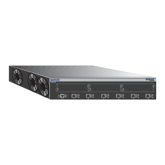
Introduction This chapter introduces the Matrix E1 1G582-09 and1G587-09 standalone network switching devices. When the information applies to both devices, the devices will be referred to as 1G58x-09. Important Notice Depending on the firmware version used in the device, some features described in this document may not be supported. - Page 22 1G582-09 or 1G587-09 (1G58x-09) 1G582-09 or 1G587-09 (1G58x-09) The 1G58x-09 switching functions can be configured using the WebView™ application, CLI switching commands, or SNMP. The 1G58x-09 device can be installed as a tabletop unit or installed into a standard 19-inch rack using the supplied rack mounting hardware.
-
Page 23: Connectivity
Connectivity CONNECTIVITY The type of connectivity is dependent on the device fixed front-panel ports and the optional Ethernet expansion module installed as described in the following sections. 1.2.1 1G582-09 Fixed Ports The 1G582-09 connects to Ethernet networks or workstations via six fixed front panel RJ45 connectors. - Page 24 Connectivity Figure 1-2 Optional Ethernet Expansion Modules (Port 1 identified) 1G-2GBIC 1H-16TX 1G-2MGBIC 1G-2MGBIC 1G-2TX 1H-8FX Table 1-1 Optional Ethernet Expansion Modules, Compliance, and Physical Connection Ethernet Expansion Module... Compliant to... With... 1H-16TX 10/100BASE-TX Sixteen fixed RJ45 connectors 1G-2TX 1000BASE-TX Two fixed RJ45 connectors 1G-2GBIC 1000BASE-SX/LX...
-
Page 25: Standards Compatibility
STANDARDS COMPATIBILITY The 1G58x-09 is fully compliant with the IEEE 802.1D, 802.1Q, and 802.3 standards. GETTING HELP For additional support related to the devices or this document, contact Enterasys Networks using one of the following methods: World Wide Web http://www.enterasys.com... -
Page 27: Network Requirements
Before connecting the device to a network so it can take advantage of the Port Trunking feature, there are certain rules concerning port connections and configurations that must be followed for proper operation. Refer to the Matrix E1 Series (1G58x-09 and 1H582-xx) Configuration Guide for additional information. -
Page 28: 100Base-Tx Network
100BASE-TX Network NOTE: If a port is to operate at 100 or 1000 Mbps, Category 5 cabling must be used. Category 3 cabling does not meet the 100 or 1000 Mbps specifications. For 10 Mbps operation only, Category 3, Category 4, or Category 5 cabling can be used. Refer to Section 2.3 Section 2.6 for information about 100BASE-TX and 1000BASE-TX... -
Page 29: Hardware Installation
Hardware Installation ELECTRICAL HAZARD: Only qualified personnel should install the 1G58x-09. NOTE: Read the Release Notes shipped with the device to check for any exceptions to the supported features and operation documented in this guide. This chapter provides the instructions required to install the 1G58x-09. Follow the order of the sections as listed below to correctly install the device. -
Page 30: Unpacking The Device
Power Cord 3. Remove the tape seal on the non-conductive bag to remove the device. 4. Perform a visual inspection of the device for any signs of physical damage. Contact Enterasys Networks if there are any signs of damage. Refer to Section 1.4... -
Page 31: Installing An Optional Ethernet Expansion Module
Installing an Optional Ethernet Expansion Module The 1G58x-09 has three expansion slots for optional Ethernet expansion modules. At the time of this printing, five Ethernet expansion module options were available for the 1G58x-09. Refer to your release notes for the latest available Ethernet expansion modules. The five optional Ethernet expansion modules include the following: •... -
Page 32: Removing The Front Panel Coverplate
Installing an Optional Ethernet Expansion Module 3.4.1 Removing the Front Panel Coverplate Refer to Figure 3-1 and proceed as follows: 1. Attach the antistatic wrist strap (refer to the instructions on the antistatic wrist strap package). ➀ 2. Place the 1G58x-09 on an antistatic pad (not shown) on a sturdy flat surface. - Page 33 Installing an Optional Ethernet Expansion Module ➀ 3. Rotate the two levers back into their center positions to fully seat the module rear ➄ connectors ➅ ➁ 4. Tighten the two captive screws to secure the Ethernet expansion module to the device front ➆...
-
Page 34: Removing The Ethernet Expansion Module
This completes the removal procedure. INSTALLING OPTIONAL GBICs The optional Enterasys Networks GBICs (models GPIM-01, GPIM-08, and GPIM-09) are hot-swappable and may be installed into the Ethernet expansion module whether or not the device is powered up. In either case, use the following installation instructions to prevent damaging either the GBIC or the host Ethernet expansion module. -
Page 35: Side Clip Gbics
Installing the Side Clip GBIC Figure 3-3 Different Physical Styles of GBICs À Á ➀ ➁ Side clip Locking bar After installing a GBIC, refer to Section 3.8 for details on connecting the GBIC to the network. 3.5.1 Side Clip GBICs This section applies only to side clip GBICs. -
Page 36: Removing The Side Clip Gbic
Removing the Side Clip GBIC ➄ ➅ 4. Insert the GBIC (20-pin connector side) into the port slot with the top of the GBIC adjacent to the door hinge of the slot. CAUTION: If the GBIC does not insert easily in this step, do not force it (check the orientation against Figure 3-4). -
Page 37: Locking Bar Gbics
Installing the Locking Bar GBIC To remove the GBIC from the 1G-2GBIC, proceed as follows: 1. Attach the antistatic wrist strap (refer to the instructions in the antistatic wrist strap package) before removing the GBIC. 2. Remove any cables connected to the GBIC. ➆... - Page 38 Installing the Locking Bar GBIC ➂ 2. Lift the metal locking bar upwards as far as it will go. See Figure 3-5, View A. This unlocks the GBIC clips. ➀ ➃ ➄ 3. Hold the GBIC with the network port facing away from the 1G-2GBIC .
-
Page 39: Removing The Locking Bar Gbic
If there is significant resistance while attempting to close the locking bar, remove the GBIC. Inspect it for any problems with the connectors. If there are any problems, contact Enterasys Networks for technical support (refer to “Getting Help”... - Page 40 Preparation To prepare and install a Mini-GBIC into the 1G-2MGBIC, proceed as follows: Preparation Before installing the Mini-GBIC, proceed as follows: 1. Attach the antistatic wrist strap (refer to the instructions in the antistatic wrist strap package) before removing the Mini-GBIC from the antistatic packaging. 2.
- Page 41 Installation Figure 3-6 Mini-GBIC with MT-RJ Connector 1G-2MGBIC 1G-2MGBIC Á Ã Â À Ä Å ➀ ➃ Mini-GBIC 1G-2MGBIC port slot ➁ ➄ Mini-GBIC top side Mini-GBIC protective dust cover ➂ ➅ 7-pin edge connector (insertion side) Locking tab Figure 3-7 Mini-GBIC with LC Connector 1G-2MGBIC Ã...
-
Page 42: Installing The Device
Removing the Mini-GBIC Removing the Mini-GBIC CAUTION: Do NOT remove a Mini-GBIC from a slot without releasing the locking tab located under the front bottom end of the Mini-GBIC This can damage the Mini-GBIC. The Mini-GBIC, 1G-2MGBIC, and 1G58x-09 are sensitive to static discharges. Use an antistatic wrist strap and observe all static precautions during this procedure. -
Page 43: Rackmount Installation
Guidelines for Rackmount Installation Figure 3-8 Clearance Required for Tabletop or Shelf Installation 1G582-09 RESET A = 15 cm (6 in) B = 57 cm (22.5 in) C = 53 cm (21 in) D = 213 cm (7 ft) 3.7.1 Rackmount Installation To install the device in a 19-inch rack, you need the following items shipped with the device. -
Page 44: Installation
Installation 3.7.1.2 Installation Rack mounting the device involves the following: • Attaching the strain-relief bracket • Rack mounting the device (attaching the mounting brackets and fastening the device to the rack) 3.7.2 Attaching the Strain-Relief Bracket To attach the strain-relief bracket to the device, refer to Figure 3-9 and proceed as follows: ➀... -
Page 45: Rack Mounting The Device
Installation 3.7.3 Rack Mounting the Device Proceed as follows to install the device into a 19-inch rack: ➀ 1. Attach the rackmount brackets to the device, as shown in Figure 3-10, using the eight ➁ M4 x 6 mm flathead screws shipped with the device. -
Page 46: Connecting Power
Installation Figure 3-11 Fastening the Device to the Rack À 1G582-09 RESET Á ➀ ➁ Rails of 19-inch rack Mounting screws (supplied by user) 3.7.4 Connecting Power NOTE: The two power supplies in the device have automatic voltage sensing that allows connection to power sources ranging from 100–125 Vac, 2.5 A or 200–240 Vac, 1.25 A, 50/60 Hz. -
Page 47: Connecting To The Network
Connecting to the Network Figure 3-12 Device, Rear View Á À Â ➀ ➂ AC power cords AC power outlets. Each outlet is on a separate circuit. ➁ AC power receptacles 3. Observe the LANVIEW LEDs. The Power (PWR) LED (not shown), located on the front panel, turns ON (green) and the CPU turns red until the device completes its initialization. -
Page 48: Connecting Utp Cables
Connecting to the Network 3.8.1 Connecting UTP Cables The fixed front panel ports of the 1G582-09 are 10/100/1000 RJ45 ports and have internal crossovers. When connecting a workstation to these ports, use a straight-through cable. When connecting networking devices to these ports, such as a bridge, repeater, or router, use a crossover cable. - Page 49 Ensure that the twisted pair connection meets the dB loss and cable specifications outlined in the Cabling Guide. Refer to “Related Documents” in About This Guide for information on obtaining this document. 4. If a link is not established, contact Enterasys Networks. Refer to “Getting Help” in Section 1.4 for details.
- Page 50 Connecting to the Network Figure 3-15 Four-Wire Straight-Through Cable RJ45 Pinouts for 10/100BASE-TX À Á RX– RX– Ã TX– TX– Â ➀ ➂ RJ45 device port RJ45-to-RJ45 straight-through cable ➁ ➃ Other device port RX+/RX- and TX+/TX- connections. These connections must share a common color pair. Figure 3-16 Eight-Wire Crossover Cable RJ45 Pinouts for 10BASE-T/100BASE-TX/1000BASE-T Á...
-
Page 51: Connecting Fiber-Optic Cables To Gbics
3.8.2 Connecting Fiber-Optic Cables to GBICs The Enterasys Networks GBICs (Models GPIM-01, GPIM-08, and GPIM-09) have SC style connectors to connect cables from the Gigabit Ethernet network. Enterasys Networks offers fiber-optic cables that use SC style connectors, which are keyed to ensure proper crossover of the transmit and receive fibers. -
Page 52: Gpim-09 Connection Using Multimode Cable
The following procedure is not needed when connecting single mode fiber-optic cable to the GPIM-09. Launch Mode Conditioning cables are available from Enterasys Networks. To connect the GPIM-09 to the network using multimode fiber-optic cables, refer to Figure 3-18 and proceed as follows: ➀... -
Page 53: Network Connection Using Fiber-Optic Cable
Connecting to the Network 3.8.4 Network Connection Using Fiber-Optic Cable To connect the device using fiber-optic cable to the network, perform the following steps: NOTE: If connecting the device with a GPIM-09 to the network using multimode fiber-optic cables, refer to Section 3.8.3 before following this procedure. - Page 54 If a link has not been established, refer to Chapter 4 for LED troubleshooting details. Refer to “Getting Help” in Section 1.4 for details on contacting Enterasys Networks if a problem persists. 3-26 Hardware Installation...
-
Page 55: Connecting Fiber-Optic Cables To Mt-Rj Ports
The receive strand of the applicable MT-RJ port connects to the transmit port of the fiber-optic Fast Ethernet device. Enterasys Networks recommends labeling fiber-optic cables to indicate receive and transmit ends. Many cables are pre-labeled, providing matching labels or tapes at both ends of each strand of cable. - Page 56 Connecting to the Network Figure 3-20 Cable Connection to MT-RJ Multimode Fiber-Optic Connectors 1H-8FX 1G-2MGBIC À Ã Ä Â Á ➀ ➃ MT-RJ port connector Receive LED (RX) ➁ ➄ MT-RJ cable connector Transmit LED (TX) ➂ Release tab 3. Plug the other end of the cable into the appropriate port on the other device. Some cables may be terminated at the other end with two separate connectors, one for each fiber-optic strand.
-
Page 57: Connecting To Console Port For Local Management
(Figure 3-21), proceed as follows: 1. Connect the RJ45 connector at one end of the cable ➀ to the Console port ➁ on the Enterasys Networks module. 2. Plug the RJ45 connector at the other end of the cable ➀ into the RJ45-to-DB9 adapter ➂. -
Page 58: Connecting To A Vt Series Terminal
UTP cable with RJ45 connectors and an optional RJ45-to-DB25 female adapter (PN 9372110), and proceed as follows: 1. Connect the RJ45 connector at one end of the cable ➀ to the Console port ➁ on the Enterasys Networks device. -
Page 59: Connecting To A Modem
➃ RJ45 console port 3.9.4 Connecting to a Modem To connect a modem to an Enterasys Networks device modem port (Figure 3-23), use a UTP cable with RJ45 connectors and an optional RJ45-to-DB25 male adapter (PN 9372112), and proceed as follows: 1. - Page 60 Connecting to Console Port for Local Management 2. Plug the RJ45 connector at the other end of the cable ➀ into the RJ45-to-DB25 male adapter ➂. 3. Connect the RJ45-to-DB25 adapter ➂ to the communications port of the modem ➃. 4.
-
Page 61: Adapter Wiring And Signal Assignments
Connecting to Console Port for Local Management 3.9.5 Adapter Wiring and Signal Assignments Console Port Adapter Wiring and Signal Diagram RJ45 Conductor Signal Blue Receive (RX) Transmit (TX) Green Ground (GRD) Orange Request to Send (RTS) Yellow Clear to Send (CTS) Pins Pins RJ45 Connector (Female) -
Page 62: 3.10 Completing The Installation
For details on how to configure the 1G582-09 using the command line interface, refer to the Matrix E1 Series (1G58x-09 and 1H582-xx) Configuration Guide. The CLI commands enable you to initially set up and perform more involved switch management configurations. - Page 63 Refer to the Matrix E1 (1G582-09 and 1H582-51) WebView User’s Guide for details. The guides are available online at: http://www.enterasys.com/support/manuals If you require assistance, contact Enterasys Networks using one of the methods described in “Getting Help” in Section 1.4.
-
Page 65: Troubleshooting
• Using the Reset switch (Section 4.3) USING LANVIEW The 1G58x-09 uses the Enterasys Networks built-in visual diagnostic and status monitoring system called LANVIEW. The LANVIEW LEDs (Figure 4-1) allow you to quickly observe network status for diagnosing network problems. - Page 66 If the LED remains red for several minutes, functional, or the system the system may have a fatal error. Contact is experiencing a fatal Enterasys Networks for technical support. error. Amber Solid. Power-up testing If the LED remains amber for more than in progress.
-
Page 67: Troubleshooting Checklist
1. Ensure that the STA is enabled and that (Receive/ activity. there is a valid link. Transmit) Should flash green every 2. Contact Enterasys Networks for two seconds indicating technical support. BPDUs being sent if STA is enabled and there is a valid link. - Page 68 Troubleshooting Checklist Table 4-2 Troubleshooting Checklist (Continued) Problem Possible Cause Recommended Action No local Incorrect terminal setup. Refer to the Matrix E1 Series (1G58x-09 and management 1H582-xx) Configuration Guide for proper startup screen. setup procedures. Improper console cable Refer to...
- Page 69 User parameters Position of Mode switch Reenter the lost parameters as necessary. (IP address, (7), NVRAM Reset, was Refer to Matrix E1 Series (1G58x-09 and device and changed sometime before 1H582-xx) Configuration Guide for the module name, either cycling power or instructions to configure the device using etc.) were lost...
-
Page 70: Using The Reset Switch
Using the Reset switch USING THE RESET SWITCH The Reset switch shown in Figure 4-1 resets and re-initializes the device, causing all user-entered parameters to reset to the factory default settings. CAUTION: Pressing the Reset switch resets the device, and all current switching being performed by the device is halted. - Page 71 Ethernet Expansion Module specifications (Section A.2) • Mini-GBIC specifications (Section A.3) • GPIM specifications (Section A.4) • Console port pinout assignment (Section A.5) • Regulatory compliance (Section A.6) Enterasys Networks reserves the right to change the specifications at any time without notice. Specifications...
-
Page 72: 1G582-09 And 1G587-09 Specifications
Six, Ethernet (10BASE-T/100BASE-TX/ 1000BASE-T) compliant ports via RJ45 front-panel connectors Ethernet Interface Option Slots Three slots that support the Enterasys Network Ethernet expansion modules. Refer to Section A.2 for a description of those modules supported. All option slots can be populated with the same type, or a mix, of different Ethernet expansion modules. -
Page 73: Ethernet Expansion Module Specifications
5% to 90% (non-condensing) ETHERNET EXPANSION MODULE SPECIFICATIONS At the time of this printing, five Ethernet expansion modules were available from Enterasys Networks. The following sections describe their input/output port specifications as follows: Table A-2 Ethernet Expansion Module Input/Output Port Specifications... -
Page 74: Ethernet Expansion Module Physical Properties
Mini-GBIC Specifications A.2.1 Ethernet Expansion Module Physical Properties Dimensions 2.06 H x 13.41 W x 17.75 D (cm) 0.81 H x 5.28 W x 6.99 D (in.) Approximate Weight (Unit) 0.45 kg (1.0 lb) MINI-GBIC SPECIFICATIONS The Mini-Gigabit Ethernet Card (Mini-GBIC) port interface slots on the 1G587-09 device and the optional 1G-2MGBIC expansion module can accept 1000BASE-SX short wavelength or 1000BASE-LX long wavelength fiber-optic Mini-GBICs (see Table... -
Page 75: Mgbic-Lc01 / Mgbic-Mt01 Specifications (1000Base-Sx
Mini-GBIC Specifications A.3.1 MGBIC-LC01 / MGBIC-MT01 Specifications (1000BASE-SX) Table A-4 Table A-5 provide the optical and operating range specifications for the MGBIC-LC01 and the MGBIC-MT01 Mini-GBICs. Table A-4 MGBIC-LC01 / MGBIC-MT01 Optical Specifications Item 62.5 µm MMF 50 µm MMF Transmit Power (minimum) -9.5 dBm -9.5 dBm... -
Page 76: Mgbic-08 Specifications (1000Base-Ex
Mini-GBIC Specifications Table A-7 MGBIC-LC09 Operating Range Modal Bandwidth @ Item 1300 nm Range 62.5 µm MMF 500 MHz/km 2-550 Meters 50 µm MMF 400 MHz/km 2-550 Meters 50 µm MMF 500 MHz/km 2-550 Meters 10 µm SMF 2-10,000 Meters A.3.3 MGBIC-08 Specifications (1000BASE-EX) Table A-8 MGBIC-08 Optical Specifications... -
Page 77: Mgbic-02 Specifications (1000Base-T
GPIM Specifications A.3.4 MGBIC-02 Specifications (1000BASE-T) Table A-10 MGBIC-02 Specifications Item Specification Supported Cable: Type Copper, Category 5 UTP Maximum Length Up to 100 meters Connector RJ45 Data Rate 1 Gbps, IEEE 802.3:2000 compatible 1000BASE-T operation only Automatic crossover detection TX Output impedance 100 ohms, typical at all frequencies between 1 MHz and 125 MHz RX Input impedance 100 ohms, typical at all frequencies between 1 MHz and 125 MHz... -
Page 78: Gpim-01 Specifications (1000Base-Sx
GPIM Specifications A.4.1 GPIM-01 Specifications (1000BASE-SX) Table A-12 Table A-13 provide the optical and operating range specifications for the GPIM-01. Table A-12 GPIM-01 Optical Specifications Item 62.5 µm MMF 50 µm MMF Transmit Power (minimum) -9.5 dBm -9.5 dBm Receive Sensitivity -17 dBm -17 dBm Link Power Budget... -
Page 79: Gpim-09 Specifications (1000Base-Sx/Lx
GPIM Specifications A.4.3 GPIM-09 Specifications (1000BASE-SX/LX) Table A-16 Table A-17 provide the optical and operating range specifications for the GPIM-09. Table A-16 GPIM-09 Optical Specifications Item 62.5 µm MMF 50 µm MMF 10 µm MMF Transmit Power (minimum) -11.5 dBm -11.5 dBm -9.5 dBm Receive Sensitivity... -
Page 80: Console Port Pinout Assignments
Console Port Pinout Assignments CONSOLE PORT PINOUT ASSIGNMENTS The Console port is a serial communications port that supports local management of the 1G58x-09. Refer to Table A-18 for the Console port pin assignments. Table A-18 Console Port Pin Assignments Signal Name Input/Output Transmit Data (XMT) Output... -
Page 81: Optional Installations And Mode Switch Bank Settings
Optional Installations and Mode Switch Bank Settings ELECTRICAL HAZARD: ONLY QUALIFIED SERVICE PERSONNEL SHOULD ATTEMPT THE FOLLOWING PROCEDURES. NUR QUALIFIEZIERTE SERVICE PERSONNAL DIE FOLGENDE PROCEDURE FOLGEN SOLLTEN. SOLAMENTE PERSONAL CALIFICADO DEBE INTENTAR ESTE PROCEDIMIENTO. The top cover must be removed to gain access to the mode bank switches, and to install an optional DRAM Single In-line Memory Modules (SIMMs). -
Page 82: Removing The Chassis Cover
Removing the Chassis Cover REMOVING THE CHASSIS COVER This section describes how to remove the 1G58x-09 chassis cover. ELECTRICAL HAZARD: DO NOT REMOVE THE COVER FROM THE DEVICE WHILE POWER IS APPLIED TO THE UNIT. HAZARDOUS VOLTAGES ARE PRESENT AND COULD CAUSE PERSONAL INJURY AND/OR DAMAGE THE UNIT. - Page 83 Removing the Chassis Cover ELECTRICAL HAZARD: TURN OFF THE DEVICE BY UNPLUGGING THE POWER CORD FROM THE REAR OF THE CHASSIS. AM HINTEN DES DEVICE STECHEI ABZIEHEN UM AUS ZU SCHALTEN. APAGUE EL DEVICE DESENCHUFE EL CABLE DE LA UNIDAD. TIP: Before performing step b, mark the cables connected to the device according to their associated port numbers.
-
Page 84: Setting The Mode Switches
Setting the Mode Switches ➁ ➂ 4. Remove the top cover by lifting it straight up and off the chassis . If you are setting the mode switches, proceed to Section B.3. If you are replacing a SIMM, proceed to Section B.4. - Page 85 Setting the Mode Switches Figure B-2 Mode Switch Location (Chassis, Top View) À Power Supply Power Supply Power Supply Power Supply MODE SWITCH BANK ➀ Mode Switch Bank Optional Installations and Mode Switch Bank Settings...
-
Page 86: Simm Replacement Procedure
In the event that the DRAM Single In-line Memory Module (SIMM) needs to be replaced, this section explains how to access and locate the SIMM. If you have questions concerning the replacement of the SIMM, refer to Section 1.4 for details on how to contact Enterasys Networks. B.4.1 Locating SIMMs ➀... -
Page 87: Installing The Dram Simm
SIMM Replacement Procedure ➀ ➁ 3. Push the release tabs away from the DRAM SIMM , as shown in Figure B-4 ➂ simultaneously lift the DRAM SIMM enough to release it from the connector 4. Rotate the DRAM SIMM ➁ upwards as shown in Figure B-4 and remove it from the connector ➂. - Page 88 SIMM Replacement Procedure Figure B-5 Installing the DRAM Â Ã Ä Ã À Á Ä ➀ ➂ ➄ SIMM alignment notch Connector fingers SIMM alignment notches (2) ➁ ➃ SIMM Connector clips 3. Reconnect the device to the network as follows: a.
- Page 89 Index Numerics Connecting to the network 3-19 Connectivity 1000BASE-SX/LX network connections introduction to requirements for Console port 1000BASE-T pin assignments A-10 requirements for 100BASE-FX requirements Device features 100BASE-T Document conventions xviii requirements 100BASE-TX requirements 10BASE-T Electromagnetic Compatibility (EMC) connection 3-20 requirements A-10 requirements...
- Page 90 Pinouts crossover 3-21, 3-22 Input/Output Ports straight-through 3-22, 3-23 Mini-GBIC specifications Power connection 3-18 Installation connecting to the network 3-19 GBIC fiber optic network connections 3-25 Receive/Transmit LEDs GBICs viewing of in a rack 3-15 Regulatory Compliance A-10 locking bar GBICs Related manuals xvii Mini-GBICs...
Need help?
Do you have a question about the Matrix E1 Series and is the answer not in the manual?
Questions and answers