Table of Contents
Advertisement
Advertisement
Table of Contents

Related Manuals for Enterasys Matrix E1 1H582-51


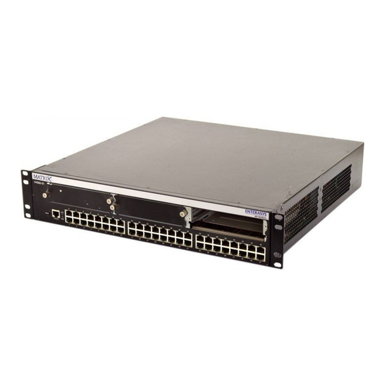
Summary of Contents for Enterasys Matrix E1 1H582-51
- Page 1 Matrix E1 Series (1G58x-09 and 1H582-xx) WebView User’s Guide 9033782-01...
- Page 3 Enterasys Networks reserves the right to make changes in specifications and other information contained in this document without prior notice. The reader should in all cases consult Enterasys Networks to determine whether any such changes have been made. The hardware, firmware, or software described in this document is subject to change without notice.
-
Page 4: Program License Agreement
This document is an agreement (“Agreement”) between You, the end user, and Enterasys Networks, Inc. (“Enterasys”) that sets forth your rights and obligations with respect to the Enterasys software program (“Program”) in the package. The Program may be contained in firmware, chips or other media. UTILIZING THE ENCLOSED PRODUCT, YOU ARE AGREEING TO BECOME BOUND BY THE TERMS OF THIS AGREEMENT, WHICH INCLUDES THE LICENSE AND THE LIMITATION OF WARRANTY AND DISCLAIMER OF LIABILITY. - Page 5 52.227-19 (a) through (d) of the Commercial Computer Software-Restricted Rights Clause and its successors, and (iii) in all respects is proprietary data belonging to Enterasys and/or its suppliers. For Department of Defense units, the Product is considered commercial computer software in accordance with DFARS section 227.7202-3 and its successors, and use, duplication, or disclosure by the Government is subject to restrictions set forth herein.
-
Page 7: Table Of Contents
Port Designations in WebView... 2-7 WEBVIEW LOCAL MANAGEMENT TASKS Overview ... 3-1 System Screen... 3-2 Switch Information Screen ... 3-4 IP Configuration Screen ... 3-5 SNMP Traps Configuration Screen... 3-6 SNMP Community Names Screen... 3-8 Security Configuration Screen ... 3-10 TFTP Download Management Screen... - Page 8 3.10 STA Information Screen... 3-14 3.11 STA Global Configuration Screen ... 3-18 3.12 STA MST GENERAL CONFIGuration ... 3-21 3.13 STA Miscellaneous Port Configuration Screen ... 3-23 3.14 STA MST Instance Configuration Screen ... 3-25 3.15 STA spanguard Configuration Screen ... 3-27 3.16 Bridge Extension Configuration Screen ...
-
Page 9: Figures
Expansion Module and Fixed Front Panel Port Numbering Scheme ... 2-8 Sample Consecutive Port Numbering for Optional Expansion Modules ... 2-8 System Screen ... 3-2 Switch Information Screen ... 3-4 IP Configuration Screen ... 3-5 SNMP Traps Configuration Screen ... 3-6 SNMP Community Names Screen ... - Page 10 Screen Designations and Functions in the Navigation Frame ...2-4 Port Numbering Scheme with Expansion Modules Installed ...2-9 System Screen Field and Link Descriptions ...3-3 Switch Information Screen Element Descriptions ...3-4 IP Configuration Screen Element Descriptions...3-5 SNMP Traps Configuration Screen Element Descriptions...3-7 SNMP Community Names Screen Element Descriptions...3-9...
-
Page 11: About This Guide
Welcome to the Enterasys Networks Matrix E1 Series (1G582-09 and 1H582-51) WebView User’s Guide. This manual explains how to perform Local Management tasks on the Matrix E1 1G582-09 and 1H582-51 devices using WebView. Enterasys Networks’ HTTP-based Web management application, WebView is an intuitive tool for initial configuration and simple management tasks. -
Page 12: Related Documents
Spanning Tree device and per-port settings, and configuring the device’s VLAN, port and port priority settings. RELATED DOCUMENTS The following Enterasys Networks documents may help you to set up, control, and manage the Matrix E1 device: •... -
Page 13: Important Notices
Enterasys Networks’ embedded Web server, WebView, provides World Wide Web (WWW) browser access to Enterasys hardware. The server is built into the Matrix E1 firmware and provides basic management and simple configuration for the device. With this tool, managers are able to manage WebView-compliant hardware from any Web-accessible location. -
Page 14: Using Webview With Matrix E1 Devices
Using WebView with Matrix E1 Devices USING WEBVIEW WITH MATRIX E1 DEVICES WebView is an intuitive tool for initial configuration and simple management tasks. It allows a network manager to perform the following tasks: • Assign a new IP address and subnet mask to the device. •... -
Page 15: Getting Help
GETTING HELP For additional support related to this device or document, contact Enterasys Networks using one of the following methods: World Wide Web http://www.enterasys.com/support Phone 1-800-872-8440 (toll-free in U.S. and Canada) For the Enterasys Networks Support toll-free number in your country: http://www.enterasys.com/support/gtac-all.html... - Page 16 Getting Help Introduction...
-
Page 17: Starting And Navigating Webview
Starting and Navigating WebView This chapter provides information about the following: • Preparing to use WebView • Starting WebView (Section • WebView security (Section • Overview of the WebView user interface • Navigating through WebView screens • Port designations in WebView PREPARING TO USE WEBVIEW Before you can use WebView for Matrix E1 Local Management, you must: 1. -
Page 18: Starting Webview
STARTING WEBVIEW To start a WebView session: 1. Open Microsoft Internet Explorer or Netscape Navigator. 2. In the address URL field, type the IP address of the WebView-enabled device you wish to access and press ENTER (example: http://10.42.42.111). The WebView Web Management login security screen, Figure Section... -
Page 19: Overview Of The Webview User Interface
Overview of the WebView User Interface OVERVIEW OF THE WEBVIEW USER INTERFACE As shown in Figure 2-2, the WebView user interface (UI) is a traditional frames presentation consisting of a navigation frame on the left side of the screen, and a content frame on the right side of the screen. -
Page 20: Navigating Webview
Links on this screen also enable you to Telnet to the textual Command Line Interface (CLI), to send email to Enterasys technical support, and to connect to the Enterasys Web page. Go to the Switch Information screen, where you can view... - Page 21 Table 2-1 Screen Designations and Functions in the Navigation Frame (Continued) Click on... Address Table Bridge Extension Priority VLAN IGMP To... Go to the Address Table Configuration screen, where you can view entries in the device’s address table, add new static address entries, remove entries, and view counts of dynamic and static addresses in the address table.
- Page 22 Table 2-1 Screen Designations and Functions in the Navigation Frame (Continued) Click on... Port Trunk Statistics Console Starting and Navigating WebView To... Go to the Port Information and Port Configuration screens, where you can view and set port administrative, link, speed, duplex and flow control status.
-
Page 23: Port Designations In Webview
PORT DESIGNATIONS IN WEBVIEW The expansion module and fixed front panel port numbering scheme used when configuring Matrix E1 ports is shown in Ethernet connections. In WebView screens with Port listings, these fixed front panel ports are designated as 1 through 48. The device’s optional expansion module slots (1, 2, and 3), can have two to 16 ports depending on the module installed. -
Page 24: Sample Consecutive Port Numbering For Optional Expansion Modules
Port Designations in WebView Figure 2-3 Expansion Module and Fixed Front Panel Port Numbering Scheme Figure 2-4 Sample Consecutive Port Numbering for Optional Expansion Modules Starting and Navigating WebView... -
Page 25: Port Numbering Scheme With Expansion Modules Installed
Table 2-2 Port Numbering Scheme with Expansion Modules Installed Port/Module Type Fixed Front Panel Forty-eight fixed RJ45 ports Fast Ethernet 10/100BASE-TX 1H-16TX Expansion Module Sixteen fixed RJ45 ports Fast Ethernet 10/100BASE-TX 1G-2TX Expansion Module Two fixed RJ45 ports Fast Ethernet 1000BASE-TX 1G-2GBIC Expansion Module... - Page 26 Port Designations in WebView 2-10 Starting and Navigating WebView...
-
Page 27: Webview Local Management Tasks
• Viewing and configuring device settings, such as the device name and location of the device (Section 3.2). • Viewing switch information, such as number of ports and the device’s firmware version (Section 3.3). • Configuring IP Address, Subnet Mask, Gateway IP, and maximum number of Telnet sessions. -
Page 28: System Screen
To view and configure system (device) settings, such as the name and location of the device. Links on this screen also enable you to Telnet to the textual Command Line Interface (CLI), to send email to Enterasys technical support, and to connect to the Enterasys Web page. How to Access Click on System in the WebView navigation frame. -
Page 29: System Screen Field And Link Descriptions
For example: “John Smith”. See the device’s uptime in days, hours, minutes and seconds. Telnet to the textual Command Line Interface (CLI) for this device. Send email to Enterasys technical support. Connect to the Enterasys Web page. WebView Local Management Tasks... -
Page 30: Switch Information Screen Element Descriptions
To view information about the main system board, including serial number, number of ports, and hardware and firmware versions. How to Access Click on Switch on the WebView navigation frame. The Switch Information screen, displays. Screen Example Figure 3-2 Switch Information Screen... -
Page 31: Ip Configuration Screen Element Descriptions
IP CONFIGURATION SCREEN When to Use To configure the host IP state, IP address, subnet mask, gateway IP address, and maximum number of Telnet sessions allowed, and to view the device’s MAC address. How to Access Click on IP on the WebView navigation frame. The IP Configuration screen, Screen Example Figure 3-3 IP Configuration Screen Screen Element Descriptions... -
Page 32: Snmp Traps Configuration Screen
SNMP Traps Configuration Screen SNMP TRAPS CONFIGURATION SCREEN When to Use To assign IP addresses where SNMP traps will be sent, to enable or disable traps, and to access the SNMP Community Names screen, where SNMP community names and access policies associated with these traps can be set. -
Page 33: Snmp Traps Configuration Screen Element Descriptions
Screen Element Descriptions Refer to Table 3-4 for a functional description of each screen element. Table 3-4 SNMP Traps Configuration Screen Element Descriptions Use this field… To… Trap Destinations Enter a destination IP address for an SNMP trap. This identifies the network management station where SNMP alerts of status changes will be sent. -
Page 34: Snmp Community Names Screen
SNMP Community Names Screen SNMP COMMUNITY NAMES SCREEN When to Use To set SNMP community names and access policies. How to Access Click on SNMP on the WebView navigation frame. The SNMP Traps Configuration screen, Figure 3-4, displays. Click on SNMP Community Names on the content frame. The SNMP Community Names screen, Figure 3-5, displays. -
Page 35: Snmp Community Names Screen Element Descriptions
Screen Element Descriptions Refer to Table 3-5 for a functional description of each screen element. Table 3-5 SNMP Community Names Screen Element Descriptions Use this field… To… Community Name Enter a community name through which a user will access SNMP management. -
Page 36: Security Configuration Screen Element Descriptions
SECURITY CONFIGURATION SCREEN When to Use To set a new login password for the device. How to Access Click on Security on the WebView navigation frame. The Security Configuration screen, Figure 3-6, displays. Screen Example Figure 3-6 Security Configuration Screen Screen Element Descriptions Refer to Table 3-6... -
Page 37: Tftp Download Management Screen Element Descriptions
TFTP DOWNLOAD MANAGEMENT SCREEN When to Use To download a new firmware image from a TFTP server to the device. How to Access Click on Upgrade on the WebView navigation frame. The TFTP Download Management screen, Figure 3-7, displays. Screen Example Figure 3-7 TFTP Download Management Screen Screen Element Descriptions Refer to... -
Page 38: Address Table Configuration Screen
ADDRESS TABLE CONFIGURATION SCREEN When to Use To view entries in the device’s address table, add new static address entries, remove entries, and view counts of dynamic and static addresses in the address table. How to Access Click on Address Table on the WebView navigation frame. The Address Table Configuration screen, Figure 3-8, displays. -
Page 39: Address Table Configuration Screen Element Descriptions
Table 3-8 Address Table Configuration Screen Element Descriptions Use this field or button… Address Table MAC Address VLAN (1-4094) Port Status Aging Time (10-630): Dynamic Address Counts: Static Address Counts: To… See the device’s current address table entries. Enter a MAC address for a new static address table entry. Enter a number (1 to 4094) identifying the VLAN to which the MAC address belongs. -
Page 40: Sta Information Screen
STA Information Screen 3.10 STA INFORMATION SCREEN When to Use To view Spanning Tree Algorithm (STA) information about the device and about each port, and to access the STA Global Config, STA MST General Configuration, STA Misc Port Config, STA MST Instance Config, and the STA Spanguard Config screens. -
Page 41: Sta Information Screen Element Descriptions
Bridge ID See a unique identifier for this bridge, consisting of bridge priority plus MAC address (where the address is taken from the switch system). Max Age See the maximum number of seconds (6 to 40) the bridge device will wait to receive a configuration message before attempting to reconfigure. - Page 42 Table 3-9 STA Information Screen Element Descriptions (Continued) Use this field… To… Root Path Cost See the path cost from the root port on this device to the root device. Configuration See a count of STA configuration changes known to the device. Changes Last Topology See the time elapsed since the last STA topology change in days,...
- Page 43 • A port on a network segment with no other STA compliant bridging • If two ports of a switch are connected to the same segment and there • All ports are blocked when the switch is booted, then some of them...
-
Page 44: Sta Global Configuration Screen
3.11 STA GLOBAL CONFIGURATION SCREEN When to Use To configure Spanning Tree Algorithm (STA) settings for the device, including parameters for when the device becomes the Spanning Tree root bridge. How to Access Click on STA on the WebView navigation frame. The STA Information screen, displays. -
Page 45: Sta Global Configuration Screen Element Descriptions
To… Spanning Tree State Enable or Disable Spanning Tree on the Switch. It is recommended to leave STA enabled on the switch and disable STA on a port by port basis if needed. STA Version Select the version of Spanning Tree to run on the switch. The options are STP Compatible, RSTP, and MSTP. - Page 46 Amount of time (in seconds) the root considers a BPDU packet to be (6-40) valid. Default is 20 seconds. Forward Delay Amount of time (in seconds) the root device spends in listening or (4-30) learning mode. Default is 15 seconds. 3-20 WebView Local Management Tasks When the Switch Becomes Root:...
-
Page 47: Sta Mst General Configuration
STA MST GENERAL CONFIGuration 3.12 STA MST GENERAL CONFIGURATION When to Use To configure MST Bridge and Port Priority, Admin Path Cost, and view the Operational Path Cost for each instance of Spanning Tree. How to Access Click on STA on the WebView navigation frame. The STA Information screen, Figure 3-9, displays. -
Page 48: Sta Mst General Configuration Screen Element Descriptions
Screen Element Descriptions Refer to Table 3-13 for a functional description of each screen element. Table 3-11 STA MST General Configuration Screen Element Descriptions Use this field… To… MST Instance When using MST, allows viewing of STP parameters for each instance of MST, otherwise shows standard STP parameters. -
Page 49: Sta Miscellaneous Port Configuration Screen
STA Miscellaneous Port Configuration Screen 3.13 STA MISCELLANEOUS PORT CONFIGURATION SCREEN When to Use To configure Spanning Tree Algorithm (STA) settings for individual ports on the device. How to Access Click on STA on the WebView navigation frame. The STA Information screen, Figure 3-9, displays. -
Page 50: Sta Miscellaneous Port Configuration Screen Element Descriptions
Select to Enable or Disable the Spanning Tree algorithm (STA) on a State) port. Admin Edge Set the AdminEdge to True or False. Authorized inter-switch links should be set to false. Spanguard (if enabled) only functions on ports with AdminEdge set to True, typically set on user ports. Admin Point Set the point-to-point status of the LAN attached to this specified port. -
Page 51: Sta Mst Instance Configuration Screen
STA MST Instance Configuration Screen 3.14 STA MST INSTANCE CONFIGURATION SCREEN When to Use To configure Multiple Spanning Tree (MST) instances on the device. How to Access Click on STA on the WebView navigation frame. The STA Information screen, Figure 3-9, displays. -
Page 52: Sta Mst Instance Configuration Screen Element Descriptions
Use this field… To… Config Digest: Displays the MST configuration Digest for the switch. Bridges compare their Digest with their neighbor bridges to see if they are in the same MST region or if they are a boundary. Format Selector: Displays the value of the MST Format Selector (presently always zero). -
Page 53: Sta Spanguard Configuration Screen
STA spanguard Configuration Screen 3.15 STA SPANGUARD CONFIGURATION SCREEN When to Use To configure Spanguard on the device. Spanguard is enabled device wide and prevents any STA protocol use on unauthorized ports (Ports with adminEdge set to True). How to Access Click on STA on the WebView navigation frame. -
Page 54: Sta Spanguard Configuration Screen Element Descriptions
Enable or Disable the Spanguard feature on the device. Spanguard Traps Enable or Disable SpanGuard Traps. If enabled the switch will send a trap to the Network Management Station when the STP protocol is seen on a Port that has adminEdge set to True. -
Page 55: Bridge Extension Configuration Screen Element Descriptions
3.16 BRIDGE EXTENSION CONFIGURATION SCREEN When to Use To view bridge MIB extension capabilities configured on the device, and to set the host VLAN ID. How to Access Click on Bridge Extension on the WebView navigation frame. The Bridge Extension Configuration screen, Figure Screen Example... - Page 56 Table 3-15 Bridge Extension Configuration Screen Element Descriptions (Continued) Use this field… To… Static Entry See if the static filtering for unicast and multicast addresses function is Individual Port active. VLAN Learning See the VLAN learning mode used by the device. IVL (Independent VLAN Mode) allows each port to maintain its own VLAN filtering database.
-
Page 57: Port Priority Configuration Screen
Port Priority Configuration Screen 3.17 PORT PRIORITY CONFIGURATION SCREEN When to Use To set the default ingress port priority per port, to view the number of egress traffic classes, or transmit queues, per port, and to access the Port Traffic Class Information screen. How to Access Click on Priority on the WebView navigation frame. -
Page 58: Port Priority Configuration Screen Element Descriptions
Screen Element Descriptions Refer to Table 3-16 for a functional description of each screen element. Table 3-16 Port Priority Configuration Screen Element Descriptions Use this field… To… Port See the port number associated with the displayed priority parameters. Default Ingress User See or enter a new 802.1p port transmit priority for frames that are Priority received (ingress) without priority information in their tag header. -
Page 59: Port Traffic Class Information Screen
Port Traffic Class Information Screen 3.18 PORT TRAFFIC CLASS INFORMATION SCREEN When to Use To view port priority-to-transmit queue mapping information. How to Access Click on Priority on the WebView navigation frame. The Port Priority Configuration screen, Figure 3-16, displays. Click on Port Traffic Class Information on the content frame. The Port Traffic Class Information screen, Figure 3-17, displays. -
Page 60: Vlan Basic Information Screen
Screen Element Descriptions Refer to Table 3-17 for a functional description of each screen element. Table 3-17 Port Traffic Class Information Screen Element Descriptions Use this field… To… Port See the port number associated with the displayed priority parameters. Priority <0 - 7> See the traffic class, or transmit queue, associated with priority levels 0 through 7 for each port. -
Page 61: Vlan Basic Information Screen Element Descriptions
Screen Example Figure 3-18 VLAN Basic Information Screen Screen Element Descriptions Refer to Table 3-18 for a functional description of each screen element. Table 3-18 VLAN Basic Information Screen Element Descriptions Use this field… To… VLAN Version See the VLAN version used by the device as specified in the IEEE Number 802.1Q standard. -
Page 62: Vlan Current Table Screen
VLAN Current Table Screen 3.20 VLAN CURRENT TABLE SCREEN When to Use To view information about all static and dynamically created VLANs known to the device, such as which ports belong to a VLAN’s egress list and whether or not they are configured to transmit untagged frames. -
Page 63: Vlan Current Table Screen Element Descriptions
Screen Element Descriptions Refer to Table 3-19 for a functional description of each screen element. Table 3-19 VLAN Current Table Screen Element Descriptions Use this field… To… VLAN Entry Delete See the number of times a VLAN entry has been deleted from this Count table. -
Page 64: Vlan Static List Screen
3.21 VLAN STATIC LIST SCREEN When to Use To create new or remove existing static VLANs from the device. How to Access Click on VLAN on the WebView navigation frame. The VLAN Basic Information screen, Figure 3-18, displays. Click on VLAN Static List on the content frame. The VLAN Static List screen, Figure 3-20, displays. -
Page 65: Vlan Static Table Screen
Screen Element Descriptions Refer to Table 3-20 for a functional description of each screen element. Table 3-20 VLAN Static List Screen Element Descriptions Use this field or button… Current VLAN ID (1-4094) VLAN Name Status 3.22 VLAN STATIC TABLE SCREEN When to Use To configure a static VLAN’s egress list, including which ports belong to the list, which ports can transmit untagged frames, and which are forbidden ports. -
Page 66: Vlan Static Table Screen
VLAN Static Table Screen Screen Example Figure 3-21 VLAN Static Table Screen 3-40 WebView Local Management Tasks... -
Page 67: Vlan Static Table Screen Element Descriptions
Screen Element Descriptions Refer to Table 3-21 for a functional description of each screen element. Table 3-21 VLAN Static Table Screen Element Descriptions Use this field or button… VLAN Name Status Members Non-Members Members Non-Members Members To… Select the VLAN ID and name for which to configure VLAN parameters. -
Page 68: Vlan Static Membership By Port Screen
Table 3-21 VLAN Static Table Screen Element Descriptions (Continued) Use this field or button… Non-Members 3.23 VLAN STATIC MEMBERSHIP BY PORT SCREEN When to Use To add ports to or remove ports from a static VLAN. Static VLANs are those created by the user using the CLI or the fields in the VLAN configuration screens. -
Page 69: Vlan Port Configuration Screen
Screen Element Descriptions Refer to Table 3-22 for a functional description of each screen element. Table 3-22 VLAN Static Membership by Port Screen Element Descriptions Use this field or button… Port Number Member Non-Member 3.24 VLAN PORT CONFIGURATION SCREEN When to Use To assign default VLAN IDs to untagged frames, and to enable or disable ingress filtering on one or more ports. -
Page 70: Vlan Port Configuration Screen Element Descriptions
Screen Example Figure 3-23 VLAN Port Configuration Screen Screen Element Descriptions Refer to Table 3-23 for a functional description of each screen element. Table 3-23 VLAN Port Configuration Screen Element Descriptions Use this field… To… Port See the number of the port for which to configure default VLAN ID and ingress filtering status. -
Page 71: Igmp Configuration Screen Element Descriptions
3.25 IGMP CONFIGURATION SCREEN When to Use To enable IGMP (Internet Group Management Protocol) on the device, to configure IGMP parameters, and to access the IP Multicast Registration Table screen. How to Access Click on IGMP on the WebView navigation frame. The IGMP Configuration screen, displays. -
Page 72: Ip Multicast Registration Table Screen
IP Multicast Registration Table Screen 3.26 IP MULTICAST REGISTRATION TABLE SCREEN When to Use To view the status of IGMP groups on the device. This includes the VLAN port configured to transmit IGMP multicast transmissions, its VLAN ID, and the IP addresses of the ports asking to receive those transmissions as part of the IGMP group. -
Page 73: Ip Multicast Registration Table Screen Element Descriptions
Screen Element Descriptions Refer to Table 3-25 for a functional description of each screen element. Table 3-25 IP Multicast Registration Table Screen Element Descriptions Use this field… To… VLAN ID: Select the identifying number of the VLAN configured for IGMP. Multicast IP Select the IP address associated with the VLAN ID through which all Address:... -
Page 74: Port Information Screen
Port Information Screen 3.27 PORT INFORMATION SCREEN When to Use To view port administrative link, speed, duplex, and flow control status. To access the Port Admin/Negotiation Configuration, Port Advertised Ability Configuration, and Port Broadcast Suppression Configuration screens. How to Access Click on Port on the WebView navigation frame. -
Page 75: Port Information Screen Element Descriptions
Screen Element Descriptions Refer to Table 3-26 for a functional description of each screen element. Table 3-26 Port Information Screen Element Descriptions Use this field… To… Port See the port number associated with the displayed status information. Admin Status See whether the port is administratively Enabled (up) or Disabled (down). -
Page 76: Port Admin/Negotiation Configuration Screen
Port Admin/Negotiation Configuration Screen 3.28 PORT ADMIN/NEGOTIATION CONFIGURATION SCREEN When to Use To set port flow control, administrative, and duplex status. How to Access Click on Port on the WebView navigation frame. The Port Information screen, Figure 3-26, displays. Click on Port Admin/Negotiation Configuration on the content frame. The Port Admin/Negotiation Configuration screen, Figure 3-27, displays. -
Page 77: Port Admin/Negotiation Configuration Screen Element Descriptions
Screen Element Descriptions Refer to Table 3-27 for a functional description of each screen element. Table 3-27 Port Admin/Negotiation Configuration Screen Element Descriptions Use this field… To… Flow control mode Enable All or Disable All ports for flow control mode (only effects ports that have auto-negotiation disabled). -
Page 78: Port Advertised Ability Configuration Screen
Port Advertised Ability Configuration Screen 3.29 PORT ADVERTISED ABILITY CONFIGURATION SCREEN When to Use To manually set a port’s speed, duplex, and flow control. How to Access Click on Port on the WebView navigation frame. The Port Information screen, Figure 3-26, displays. -
Page 79: Port Advertised Ability Configuration Screen Element Descriptions
Screen Element Descriptions Refer to Table 3-28 for a functional description of each screen element. Table 3-28 Port Advertised Ability Configuration Screen Element Descriptions Use this field… To… Port See the port number associated with the displayed status information. Adv 10M Set the Port to advertise (or not) 10M Half-Duplex and/or 10M Full-Duplex. -
Page 80: Port Broadcast Suppression Configuration Screen
Port Broadcast Suppression Configuration Screen 3.30 PORT BROADCAST SUPPRESSION CONFIGURATION SCREEN When to Use To enable and set broadcast suppression on a port by port basis. How to Access Click on Port on the WebView navigation frame. The Port Information screen, Figure 3-26, displays. -
Page 81: Port Broadcast Suppression Configuration Screen Element Descriptions
Screen Element Descriptions Refer to Table 3-29 for a functional description of each screen element. Table 3-29 Port Broadcast Suppression Configuration Screen Element Descriptions Use this field… To… Port See the port number associated with the displayed status information. Broadcast Enable or Disable Broadcast Suppression per port. -
Page 82: Port Trunking Configuration Screen
Port Trunking Configuration Screen 3.31 PORT TRUNKING CONFIGURATION SCREEN When to Use To add or remove trunks on the device, and to add or remove trunk ports from existing trunks. How to Access Click on Trunk on the WebView navigation frame. The Port Trunking Configuration screen, Figure 3-30, displays. -
Page 83: Port Trunking Configuration Screen Element Descriptions
Screen Element Descriptions Refer to Table 3-30 for a functional description of each screen element. Table 3-30 Port Trunking Configuration Screen Element Descriptions Use this field or button… Trunkname Current Trunk Port To… Status List: Enter a name for the trunk to be created. Create a new trunk with the name specified. -
Page 84: Port Statistics Screen
Port Statistics Screen 3.32 PORT STATISTICS SCREEN When to Use To view port Ethernet-like MIB statistics and RMON statistics. How to Access Click on Statistics on the WebView navigation frame. The Port Statistics screen, Figure 3-31 displays. Screen Example Figure 3-31 Port Statistics Screen 3-58 WebView Local Management Tasks... -
Page 85: Port Statistics Screen Element Descriptions
Screen Element Descriptions Refer to Table 3-31 for a functional description of each screen element. Table 3-31 Port Statistics Screen Element Descriptions Use this field or button… Port Number Alignment Errors FCS Errors Single Collision Frames Multiple Collision Frames SQE Test Errors Deferred Transmissions Late Collisions Excessive Collisions... - Page 86 RMON Statistics: See the total number of times that the RMON agent was forced to discard frames due to lack of available switch resources. This does not display the number of frames dropped, only the number of times the RMON agent was forced to discard frames.
- Page 87 Table 3-31 Port Statistics Screen Element Descriptions (Continued) Use this field or button… Jabbers Collisions 64 Bytes Frames 65 – 127 Bytes Frames 128 – 255 Bytes Frames 256 – 511 Bytes Frames 512 – 1023 Bytes Frames 1024 – 1532 Bytes Frames To…...
-
Page 88: Console Configuration Screen
Console Configuration Screen 3.33 CONSOLE CONFIGURATION SCREEN When to Use To configure device console settings, such as baud rate, time out, and auto refresh rate. How to Access Click on Console on the WebView navigation frame. The Console Configuration screen, Figure 3-32, displays. -
Page 89: Console Configuration Screen Element Descriptions
Screen Element Descriptions Refer to Table 3-32 for a functional description of each screen element. Table 3-32 Console Configuration Screen Element Descriptions Use this field… To… Baudrate Select the console baud rate. Time-Out Enter the time in minutes that must elapse before the device times out. Databits Select the console’s databits. - Page 90 Console Configuration Screen 3-64 WebView Local Management Tasks...
Need help?
Do you have a question about the Matrix E1 1H582-51 and is the answer not in the manual?
Questions and answers