
Related Manuals for FuzzDog Tone Bender Mk II


Summary of Contents for FuzzDog Tone Bender Mk II
- Page 1 Tone Bender Mk II Sweet, smooth fuzz Contents of this document are ©2021 Pedal Parts Ltd. No reproduction permitted without the express written permission of Pedal Parts Ltd. All rights reserved.
-
Page 2: Important Notes
Important notes If you’re using any of our footswitch daughterboards, DOWNLOAD THE DAUGHTERBOARD DOCUMENT • Download and read the appropriate build document for the daughterboard as well as this one BEFORE you start. • DO NOT solder the supplied Current Limiting Resistor (CLR) to the main circuit board even if there is a place for it. - Page 3 Schematic - PNP (posi ground) 100K / 470R Values in black are for the Tonebender Pro 100K MkII. Substitute values in blue for Marshall 10n / SuperFuzz or red for Vox Tone Bender MkII. 4.7u / 100n The schematic above shows the original PNP - Positive-Ground layout, which is also how the PCB is designed.
- Page 4 The power and signal pads on the PCB Once everything is soldered in place you conform to the FuzzDog Direct Connection need to adjust the trimmers to bias the format, so can be paired with the appropriate transistors. Q1 is fixed bias, but you...
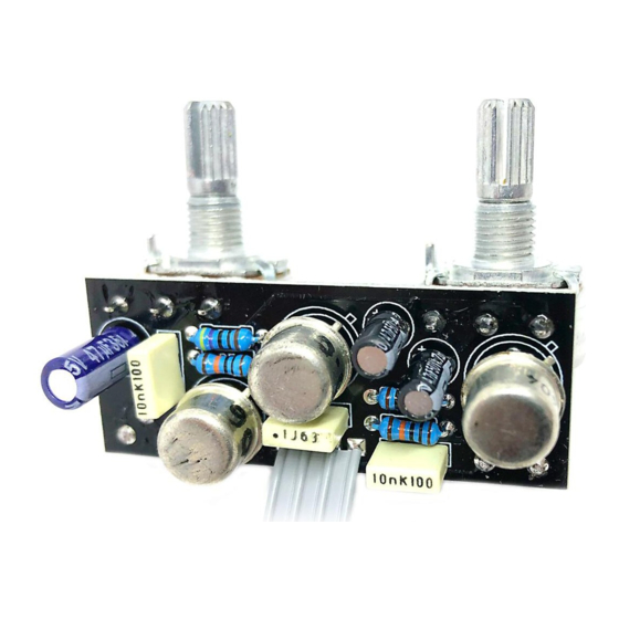
- Page 5 Test the board - PNP version UNDER NO CIRCUMSTANCES will troubleshooting help be offered if you have skipped this stage. No exceptions. Once you’ve finished the circuit it makes sense to test is before starting on the switch and LED wiring.
- Page 6 Test the board - NPN version UNDER NO CIRCUMSTANCES will troubleshooting help be offered if you have skipped this stage. No exceptions. Once you’ve finished the circuit it makes sense to test is before starting on the switch and LED wiring.
- Page 7 Wire it up - PNP (if using a daughterboard please refer to the relevant document) BOARD BOARD INPUT BOARD BOARD BOARD BOARD BATTERY BOARD Wiring shown above will disconnect the battery when you remove the jack plug from the input, and also when a DC plug is inserted. The Board GND connections don’t all have to directly attach to the board.
- Page 8 Wire it up - NPN (if using a daughterboard please refer to the relevant document) BOARD BOARD INPUT BOARD BOARD BOARD BOARD BOARD BOARD BATTERY Wiring shown above will disconnect the battery when you remove the jack plug from the input, and also when a DC plug is inserted. The Board GND connections don’t all have to directly attach to the board.
-
Page 9: Drilling Template
3 mm This template is a rough guide only. You should ensure correct marking of your enclosure before drilling. You use this template at your own risk. Pedal Parts Ltd can accept no responsibility for incorrect drilling of enclosures. FuzzDog.co.uk...
Need help?
Do you have a question about the Tone Bender Mk II and is the answer not in the manual?
Questions and answers