
Related Manuals for FuzzDog DeathDrive


Summary of Contents for FuzzDog DeathDrive
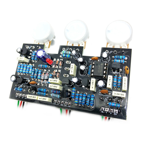
- Page 1 Death Drive Octave-up into Rat into boost for doomy destruction Contents of this document are ©2019 Pedal Parts Ltd. No reproduction permitted without the express written permission of Pedal Parts Ltd. All rights reserved.
-
Page 2: Important Notes
Important notes If you’re using any of our footswitch daughterboards, DOWNLOAD THE DAUGHTERBOARD DOCUMENT • Download and read the appropriate build document for the daughterboard as well as this one BEFORE you start. • DO NOT solder the supplied Current Limiting Resistor (CLR) to the main circuit board even if there is a place for it. - Page 3 Schematic + BOM Bigger, legible version on next page. Based on the trace by Bugg 100p OP07* 100n 100n 2N5457** 100n 2N5089 470K 100n 2N5087 1u elec 2N5089 1u elec 2N5457** BS170 100p ‡ D1-2 Ge*** 100K 1N4148 100K 3mm Red LED D5-7 1N4148 100n...
- Page 5 Two of the power and signal pads on the PCB You should solder all other board-mounted conform to the FuzzDog Direct Connection components before you solder the pots. Once format, so can be paired with the appropriate they’re in place you’ll have no access to much of daughterboard for quick and easy offboard the board.
-
Page 6: Initial Wiring
Initial wiring USE WIRES! Our ribbon cables are unlikely to be of any use unless you’ve compromised your enclosure layout to line up the pads to daughterboards. If you aren’t going to use a footswitch to engage/bypass the OCTAVE section of the circuit, add a jumper as shown below. - Page 7 Testing You can test the Distortion and Boost sections individually, as if they’re separate boards. Do the test wiring as shown below for each section. UNDER NO CIRCUMSTANCES will troubleshooting help be offered if you have skipped this stage. No exceptions. Solder some nice, long lengths of wire to the board connections for 9V, GND, IN and OUT.
- Page 8 Wire it all up The image below assumes you’re using an Octave Bypass footswitch. If not just leave that out, having added the jumper shown earlier in this document. You should also connect OV and OG to V and G on the Octave daughterboard, we just left them out of the image as it would get messy.
- Page 9 Keeping up appearances... On the bigger box versions of this kit, the LEDs all sit to the same side of the footswitches. However, that would look decidedly weird on the two switch, 1590BB version. To keep things sweet you’ll have to flip the Distortion side daughterboard over before soldering in the footswitch and LED.
- Page 10 On/Offboard wiring We designed the board to fit nicely in a 1590BB with all controls mounted on the PCB. Using a bigger enclosure means some pots need to be wired offboard. The images on the next two pages show which pots need to be wired. You may need to bend the legs down to ensure they don’t touch the PCB in some places.
-
Page 13: Drilling Templates
If you’re using a different type you’ll have to work out for yourself how far down the pots need to be to allow clearance for any lugs. On the 1590DD enclosures there’s an extra rib in the centre, so take that into consideration when drilling your middle footswitch and your DC socket hole. FuzzDog.co.uk... -
Page 14: Drilling Template
Drilling template Recommended drill sizes: Pots Jacks 10mm Hammond 1590BB Footswitch 12mm DC Socket 8/12mm Toggle switches It’s a good idea to drill the pot and toggle switch holes 1mm bigger if you’re board-mounting them. 3 mm 3 mm... - Page 15 Drilling template Recommended drill sizes: Pots Jacks 10mm Hammond 1590XX Footswitch 12mm DC Socket 8/12mm Toggle switches It’s a good idea to drill the pot and toggle switch holes 1mm bigger if you’re board-mounting them.
- Page 16 Drilling template Hammond 1590DD...
Need help?
Do you have a question about the DeathDrive and is the answer not in the manual?
Questions and answers