Table of Contents
Advertisement
Quick Links
Проконсультироваться и купить данное оборудование вы можете в компании «АНД-Системс»
адрес: 125480, г.Москва, ул.Туристская, д.33/1; site: https://andpro.ru тел: +7 (495) 545-4870 email: info@andpro.ru
При обращении используйте промокод AND-PDF и получите скидку.
S
S
UPER
ERVER
®
5018D-FN8T
USER'S MANUAL
Revision 1.0
Advertisement
Table of Contents

Related Manuals for Supermicro SUPERSERVER 5018D-FN8T


Summary of Contents for Supermicro SUPERSERVER 5018D-FN8T
- Page 1 Проконсультироваться и купить данное оборудование вы можете в компании «АНД-Системс» адрес: 125480, г.Москва, ул.Туристская, д.33/1; site: https://andpro.ru тел: +7 (495) 545-4870 email: info@andpro.ru При обращении используйте промокод AND-PDF и получите скидку. UPER ERVER ® 5018D-FN8T USER’S MANUAL Revision 1.0...
- Page 2 This product, including software and documentation, is the property of Supermicro and/or its licensors, and is supplied only under a license. Any use or reproduction of this product is not allowed, except as expressly permitted by the terms of said license.
-
Page 3: About This Manual
SuperServer. Installation and maintenance should be performed by experienced technicians only. Please refer to the server specifications page on our Web site for updates on supported memory, processors and operating systems (http://www.supermicro. com). Warnings Special attention should be given to the following symbols used in this manual. -
Page 4: Table Of Contents
Drives ......................1-4 Control Panel ....................1-4 PCI Expansion ....................1-4 Cooling System ....................1-4 Contacting Supermicro ..................1-5 Chapter 2 Installation in a Rack Preparing for Setup ..................2-1 Choosing a Setup Location ................2-1 Warnings and Precautions ................2-2 Rack Precautions .................... - Page 5 Contents Chapter 4 Standardized Warning Statements for AC Systems About Standardized Warning Statements ............4-1 Warning Definition ................... 4-1 Installation Instructions ..................4-4 Circuit Breaker ....................4-5 Power Disconnection Warning ................ 4-6 Equipment Installation ..................4-8 Restricted Area ....................4-9 Battery Handling ....................
- Page 6 UPER ERVER 5018D-FN8T Manual Chapter 6 Advanced Chassis Setup and Maintenance Static-Sensitive Devices .................. 6-1 Precautions ..................... 6-1 Removing Power from the System ..............6-2 Removing the Chassis Cover ................. 6-3 Installing Hard Drives Installing 3.5" Fixed Hard Drives ..............6-5 Installing 2.5"...
-
Page 7: Contacting Supermicro
Super Micro Computer, Inc. 980 Rock Ave. San Jose, CA 95131 U.S.A. Tel: +1 (408) 503-8000 Fax: +1 (408) 503-8008 Email: marketing@supermicro.com (General Information) support@supermicro.com (Technical Support) Web Site: www.supermicro.com Europe Address: Super Micro Computer B.V. Het Sterrenbeeld 28, 5215 ML... - Page 8 UPER ERVER 5018D-FN8T Manual Notes viii...
-
Page 9: Chapter 1 Introduction
Chapter 1: Introduction Chapter 1 Introduction Overview The SuperServer 5018D-FN8T is a compact, low-power network appliance comprised of two main subsystems: the SC505-203B 1U server chassis and the X10SDV-TP8F single processor motherboard. Certified operating systems are listed at www.supermicro.com. In addition to the motherboard and chassis, various hardware components are listed below: •... -
Page 10: Motherboard Features
SUPERSERVER 5018D-FN8T User's Manual Motherboard Features The SuperServer 5018D-FN8T is built around the X10SDV-TP8F, a single processor motherboard designed to provide maximum performance. Below are the main features. (see Figure 1-1 for a block diagram) Processors The motherboard supports a single Intel Xeon D-1518 four Core 35W embedded processor. - Page 11 Chapter 1: Introduction DDR4 1600/1866/2133 PCIE 3.0 x8 JPCIE1 PCIE 3.0 x8 PCIE 3.0 x8 JPCIE2 PCIE 3.0 x8 MINI-SAS HD PROCESSOR PCIE 3.0 x3 SAS2 LSI SAS2116 PCIE 3.0 x3 M.2 CONN SFP+ iXFI INPHI CS4227 SATA GEN 3 SATA Gen3 USB 3.0 USB 3.0 connector x2...
-
Page 12: Server Chassis Features
SUPERSERVER 5018D-FN8T User's Manual Server Chassis Features The appliance 5018D-FN8T is built on the SC505-203B, a small form factor 1U rackmount server chassis. The following is a general outline of the main features. System Power The system has a single 200 watt low-noise AC-DC power supply with PFC. -
Page 13: Contacting Supermicro
Super Micro Computer, Inc. 980 Rock Ave. San Jose, CA 95131 U.S.A. Tel: +1 (408) 503-8000 Fax: +1 (408) 503-8008 Email: marketing@supermicro.com (General Information) support@supermicro.com (Technical Support) Website: www.supermicro.com Europe Address: Super Micro Computer B.V. Het Sterrenbeeld 28, 5215 ML... - Page 14 SUPERSERVER 5018D-FN8T User's Manual Notes...
-
Page 15: Chapter 2 Installation In A Rack
Chapter 2: Installation in a Rack Chapter 2 Installation in a Rack This chapter provides instructions for mounting your chassis in a rack. Preparing for Setup The box in which your system was shipped should include the mounting screws to mount the system into the rack. Please read this chapter in its entirety before beginning the installation procedure. -
Page 16: Warnings And Precautions
SUPERSERVER 5018D-FN8T User's Manual Warnings and Precautions Rack Precautions • Ensure that the leveling jacks on the bottom of the rack are fully extended to the floor with the full weight of the rack resting on them. • In single rack installation, stabilizers should be attached to the rack. In multiple rack installations, the racks should be coupled together. -
Page 17: Rack Mounting Considerations
Chapter 2 Installation in a Rack Rack Mounting Considerations Ambient Operating Temperature If installed in a closed or multi-unit rack assembly, the ambient operating temperature of the rack environment may be greater than the ambient temperature of the room. Therefore, consideration should be given to installing the equipment in an environment compatible with the manufacturer’s maximum rated ambient temperature (Tmra). -
Page 18: Installing The System Into A Rack
SUPERSERVER 5018D-FN8T User's Manual Installing the System into a Rack The system can be installed into a rack directly using screws. Figure 2-1. Installing the Chassis into a Rack Note: Figures are for illustrative purposes only. Always install servers into racks from the bottom up. -
Page 19: Chapter 3 System Interface
Chapter 3 System Interface Chapter 3 System Interface Overview The chassis includes a control panel on the front that includes power buttons and status monitoring lights, and status lights for the power supply Figure 3-1. Control Panel... -
Page 20: Control Panel Buttons
SUPERSERVER 5018D-FN8T User's Manual Control Panel Buttons The chassis includes two push-buttons that control power to the system. Power: The main power switch is used to apply or remove power from the power supply to the server. Turning off system power with this button removes the main power but maintains standby power. -
Page 21: Overheating
Overheat Temperature Setting Some backplanes allow the overheat temperature to be set at 45, 50, or 55 degrees by changing a jumper setting. For more information, consult the backplane user manual on the Supermicro website. Responses If the server overheats 1. - Page 22 SUPERSERVER 5018D-FN8T User's Manual Notes.
-
Page 23: Chapter 4 Standardized Warning Statements For Ac Systems
Read this chapter in its entirety before installing or configuring components in the Supermicro chassis. Some warnings may not apply for your system. These warnings may also be found on our web site at http://www.supermicro.com/ about/policies/safety_information.cfm. Warning Definition Warning! This warning symbol means danger. - Page 24 SUPERSERVER 5018D-FN8T User's Manual Warnung WICHTIGE SICHERHEITSHINWEISE Dieses Warnsymbol bedeutet Gefahr. Sie befinden sich in einer Situation, die zu Verletzungen führen kann. Machen Sie sich vor der Arbeit mit Geräten mit den Gefahren elektrischer Schaltungen und den üblichen Verfahren zur Vorbeugung vor Unfällen vertraut.
- Page 25 Chapter 4: Warning Statements for AC Systems جسذٌة اصابة ًتتسبب ف حالة ٌوكي أى ًاًك ف خطز ًٌٌع هذا الزهز !تحذٌز الذوائز بالوخاطز الٌاجوة عي ي على علن ، ك هعذات تعول على أي قبل أى الكهزبائٍة حىادث أي وقىع وٌع...
-
Page 26: Installation Instructions
SUPERSERVER 5018D-FN8T User's Manual Installation Instructions Warning! Read the installation instructions before connecting the system to the power source. 設置手順書 システムを電源に接続する前に、 設置手順書をお読み下さい。 警告 将此系统连接电源前,请先阅读安装说明。 警告 將系統與電源連接前,請先閱讀安裝說明。 Warnung Vor dem Anschließen des Systems an die Stromquelle die Installationsanweisungen lesen. ¡Advertencia! Lea las instrucciones de instalación antes de conectar el sistema a la red de alimentación. -
Page 27: Circuit Breaker
Chapter 4: Warning Statements for AC Systems Circuit Breaker Warning! This product relies on the building's installation for short-circuit (overcurrent) protection. Ensure that the protective device is rated not greater than: 250 V, 20 A. サーキッ ト ・ ブレーカー この製品は、 短絡 (過電流) 保護装置がある建物での設置を前提としています。 保護装置の定格が250 V、... -
Page 28: Power Disconnection Warning
SUPERSERVER 5018D-FN8T User's Manual 경고! 이 제품은 전원의 단락(과전류)방지에 대해서 전적으로 건물의 관련 설비에 의존합니다. 보호장치의 정격이 반드시 250V(볼트), 20A(암페어)를 초과하지 않도록 해야 합니다. Waarschuwing Dit product is afhankelijk van de kortsluitbeveiliging (overspanning) van uw electrische installatie. Controleer of het beveiligde aparaat niet groter gedimensioneerd is dan 220V, 20A. - Page 29 Chapter 4: Warning Statements for AC Systems ¡Advertencia! El sistema debe ser disconnected de todas las fuentes de energía y del cable eléctrico quitado de los módulos de fuente de alimentación antes de tener acceso el interior del chasis para instalar o para quitar componentes de sistema. Attention Le système doit être débranché...
-
Page 30: Equipment Installation
SUPERSERVER 5018D-FN8T User's Manual Equipment Installation Warning! Only trained and qualified personnel should be allowed to install, replace, or service this equipment. 機器の設置 トレーニングを受け認定された人だけがこの装置の設置、 交換、 またはサービスを許可 されています。 警告 只有经过培训且具有资格的人员才能进行此设备的安装、更换和维修。 警告 只有經過受訓且具資格人員才可安裝、更換與維修此設備。 Warnung Das Installieren, Ersetzen oder Bedienen dieser Ausrüstung sollte nur geschultem, qualifiziertem Personal gestattet werden. -
Page 31: Restricted Area
Chapter 4: Warning Statements for AC Systems Waarschuwing Deze apparatuur mag alleen worden geïnstalleerd, vervangen of hersteld door geschoold en gekwalificeerd personeel. Restricted Area Warning! This unit is intended for installation in restricted access areas. A restricted access area can be accessed only through the use of a special tool, lock and key, or other means of security. -
Page 32: Battery Handling
SUPERSERVER 5018D-FN8T User's Manual אזור עם גישה מוגבלת !אזהרה יש להתקין את היחידה באזורים שיש בהם הגבלת גישה. הגישה ניתנת בעזרת .)'כלי אבטחה בלבד (מפתח, מנעול וכד محظورة مناطق ٍنتركُبها ف هذه انىحذة تخصيص تم ،أداة خاصت من خالل استخذاو... - Page 33 Chapter 4: Warning Statements for AC Systems Warnung Bei Einsetzen einer falschen Batterie besteht Explosionsgefahr. Ersetzen Sie die Batterie nur durch den gleichen oder vom Hersteller empfohlenen Batterietyp. Entsorgen Sie die benutzten Batterien nach den Anweisungen des Herstellers. Attention Danger d'explosion si la pile n'est pas remplacée correctement. Ne la remplacer que par une pile de type semblable ou équivalent, recommandée par le fabricant.
-
Page 34: Redundant Power Supplies (If Applicable To Your System)
SUPERSERVER 5018D-FN8T User's Manual Redundant Power Supplies (if applicable to your system) Warning! This unit might have more than one power supply connection. All connections must be removed to de-energize the unit. 冗長電源装置 このユニッ トは複数の電源装置が接続されている場合があります。 ユニッ トの電源を切るためには、 すべての接続を取り外さなければなりません。 警告 此部件连接的电源可能不止一个,必须将所有电源断开才能停止给该部件供电。... -
Page 35: Backplane Voltage (If Applicable To Your System)
Chapter 4: Warning Statements for AC Systems امداد الطاقة بوحدات عدة اتصاالت جهاز ال يكون لهذا قد الكهرباء عن وحدة ال لعسل كافة االتصاالت يجب إزالة 경고! 이 장치에는 한 개 이상의 전원 공급 단자가 연결되어 있을 수 있습니다. 이 장치에... -
Page 36: Comply With Local And National Electrical Codes
SUPERSERVER 5018D-FN8T User's Manual מתח בפנל האחורי !הרה אז קיימת סכנת מתח בפנל האחורי בזמן תפעול המערכת. יש להיזהר במהלך .העבודה اللىحة أوالطاقة المىجىدة على التيار الكهزبائي مه خطز هناك هذا الجهاس خدمة كه حذرا عند يعمل النظام عندما يكىن... -
Page 37: Product Disposal
Chapter 4: Warning Statements for AC Systems Attention L'équipement doit être installé conformément aux normes électriques nationales et locales. תיאום חוקי החשמל הארצי !אזהרה הציוד חייבת להיות תואמת לחוקי החשמל המקומיים והארציים התקנת المتعلقة المحلية والىطىية قىاويه يجب أن يمتثل لل الكهربائية... -
Page 38: Hot Swap Fan Warning (If Applicable To Your System)
SUPERSERVER 5018D-FN8T User's Manual ¡Advertencia! Al deshacerse por completo de este producto debe seguir todas las leyes y reglamentos nacionales. Attention La mise au rebut ou le recyclage de ce produit sont généralement soumis à des lois et/ou directives de respect de l'environnement. Renseignez-vous auprès de l'organisme compétent. - Page 39 Chapter 4: Warning Statements for AC Systems 警告 當您從機架移除風扇裝置,風扇可能仍在轉動。小心不要將手指、螺絲起子和其他 物品太靠近風扇。 Warnung Die Lüfter drehen sich u. U. noch, wenn die Lüfterbaugruppe aus dem Chassis genommen wird. Halten Sie Finger, Schraubendreher und andere Gegenstände von den Öffnungen des Lüftergehäuses entfernt. ¡Advertencia! Los ventiladores podran dar vuelta cuando usted quite ell montaje del ventilador del chasis.
-
Page 40: Power Cable And Ac Adapter
Electrical Appliance and Material Safety Law prohibits the use of UL or CSA -certified cables (that have UL/CSA shown on the code) for any other electrical devices than products designated by Supermicro only. 電源コードとACアダプター 製品を設置する場合、 提供または指定された接続ケーブル、 電源コードとACアダプター... - Page 41 Appareils électroménagers et de loi sur la sécurité Matériel interdit l'utilisation de UL ou CSA câbles certifiés qui ont UL ou CSA indiqué sur le code pour tous les autres appareils électriques que les produits désignés par Supermicro seulement.
- Page 42 SUPERSERVER 5018D-FN8T User's Manual Notes 4-20...
-
Page 43: Chapter 5 Advanced Motherboard Setup
Chapter 5: Advanced Motherboard Setup Chapter 5 Advanced Motherboard Setup This chapter covers the steps required to connect the data and power cables and install add-on cards. All motherboard jumpers and connections are also described. A layout and quick reference chart are included in this chapter for your reference. Note: For this server, the CPU heatsink are preinstalled on the motherboard, and not replacable by the user. -
Page 44: Connecting Cables
SUPERSERVER 5018D-FN8T User's Manual Connecting Cables Once the motherboard is installed, the cables must be connected. These include the data (ribbon) cables for the peripherals and control panel and the power cables. See section 5-5 for connectors. Connecting Data Cables... -
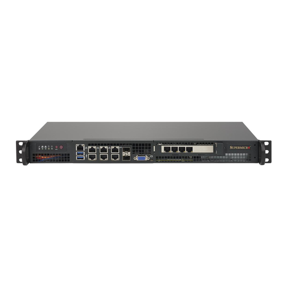
Page 45: Input/Output Ports
Chapter 5: Advanced Motherboard Setup Input/Output Ports Figure 5-1. I/O Ports Front Panel I/O A. IPMI LAN E. LAN Port 1 I. LAN Port 5 B. USB Port 1 F. LAN Port 4 J. LAN Port 8 (SFP+) C. USB Port 0 G. -
Page 46: Memory Support
SUPERSERVER 5018D-FN8T User's Manual Memory Support The X10SDV-TP8F motherboard supports up to 128GB of DDR4 ECC RDIMM or 64GB of DDR4 ECC/Non-ECC UDIMM with speeds up to 2133MHz in four memory slots. Populating these DIMM slots with memory modules of the same type and same size will result in interleaved memory, which improves memory performance. -
Page 47: Memory Installation Guidelines
Chapter 5: Advanced Motherboard Setup Memory Installation Guidelines When installing memory modules, the DIMM slots should be populated in the following order: DIMMA1, DIMMB1, then DIMMA2, DIMMB2. • Always use DDR4 DIMM modules of the same size, type and speed. Mixing memory modules of different types and speeds is not allowed. -
Page 48: Motherboard Details
SUPERSERVER 5018D-FN8T User's Manual Motherboard Details LAN7/8 JPL3 LAN5/6 LED8 IPMI LAN LAN3/4 LEDM1 LED7 USB0/1 MP-SRW1 LAN1/2 MP-SRW2 LED7 JI2C1/JI2C2: JBR1 1-2:ENABLE PRESS FIT 1-2:NORMAL BAR CODE 2-3:DISABLE 2-3:BIOS RECOVERY JPG1: 1-2:ENABLE 2-3:DISABLE JPS1:SAS 1-2:ENABLE JPL3: 2-3:DISABLE LAN3/4/5/6 M2_SRW3... - Page 49 Chapter 5: Advanced Motherboard Setup X10SDV-TP8F Headers/Connectors Connector Description Onboard Battery COM1 COM1 Header FAN1 - FAN4, CPU/System Cooling Fans FANA, FANB IPMI LAN Dedicated IPMI LAN Port I-SATA0 - I-SATA5 Intel SATA Ports (I-SATA0 / I-SATA1 support SuperDOM, I-SATA4 via M.2, I-SATA5 via Mini-PCIE mSATA) I-SGPIO1 Serial Link General Purpose I/O Headers...
-
Page 50: Led Description
SUPERSERVER 5018D-FN8T User's Manual Jumpers Jumper Description Default JBR1 BIOS Recovery Pins 1-2 (Normal) JBT1 CMOS Clear Open: Normal, Short: Clear CMOS C1/JI SMB to PCI-Exp. Slots Pins 2-3 (Disabled) JPG1 VGA Enable Pins 1-2 (Enabled) JPL1 LAN1 Enable Pins 1-2 (Enabled) -
Page 51: Connector Definitions
Chapter 5: Advanced Motherboard Setup Connector Definitions Power Connectors The 24-pin ATX power connector ATX Power 24-pin Connector header (JPW1) provides power to Pin Definitions (JPW1) the motherboard. The 12V DC power Pin# Definition Pin # Definition connector (JPV1) provides alternative +3.3V +3.3V power for a special enclosure when... - Page 52 SUPERSERVER 5018D-FN8T User's Manual Control Panel Connectors Power On LED 3.3 V HDD LED 3.3 V stby NIC1 LED (Activity) 3.3 V stby NIC2 LED (Activity) 3.3 V stby OH/Fan Fail/Pwr Fail UID LED Power Fail LED 3.3 V Ground...
- Page 53 Chapter 5: Advanced Motherboard Setup Overheat (OH)/Fan Fail/PWR Fail OH/Fan Fail/ PWR Fail/Blue_UID and UID LEDs LED Pin Definitions (JF1) Pin# Definition Pins 7 and 8 connect to the Overheat/ Blue_UID LED Fan Fail/Power Fail and UID LEDs on the front control panel. These OH/Fan Fail/Power Fail Cathode functions are described in Chapter 3.
- Page 54 SUPERSERVER 5018D-FN8T User's Manual Input/Output Connectors Universal Serial Bus (USB) Two Universal Serial Bus 3.0 ports (USB0/1) are located on the front I/O panel. One USB Type-A header (USB2) is available on the motherboard. Ethernet Ports Six Gigabit Ethernet ports (LAN1-LAN6) and two 10G SFP+ports (LAN7, LAN8) are located on the front I/O panel to provide network connections.
-
Page 55: Other Motherboard Connectors
Chapter 5: Advanced Motherboard Setup Other Motherboard Connectors Fan Headers Fan Header Pin Definitions There are six fan 4-pin headers. Pins Pin# Definition 1-3 are backward compatible with Ground (Black) the traditional 3-pin fans, but you can +12V (Red) use 4-pin fans to take advantage of Tachometer the fan speed control using Pulse PWM_Control... - Page 56 SUPERSERVER 5018D-FN8T User's Manual TPM Header/Port 80 Header Trusted Platform Module Header (JTPM1) Pin Definitions The JTPM1 header is used to connect Pin # Definition Pin # Definition a Trusted Platform Module (TPM)/ LCLK Port 80, which is available from a...
- Page 57 The System Management Bus header Pin# Definition for additional slave devices or sensors Data is located as JSMB1. Ground Clock NVMe I2C Header Connector JNVI2C is a management header for the Supermicro AOC NVMe PCI-E peripheral cards. Connect it with the I2C cable. 5-15...
-
Page 58: Jumper Settings
SUPERSERVER 5018D-FN8T User's Manual Jumper Settings Explanation of Jumpers To modify the operation of the motherboard, jumpers can be used Connector to choose between optional settings. Pins Jumpers create shorts between two pins to change the function of the connector. Pin 1 is identified with... - Page 59 Chapter 5: Advanced Motherboard Setup VGA Enable/Disable VGA Enable/Disable Jumper Settings JPG1 allows you to enable or disable Pin# Definition the VGA port. The default position is on Enabled (default) pins 1 and 2 to enable VGA. See the Disabled table on the right for jumper settings.
- Page 60 SUPERSERVER 5018D-FN8T User's Manual ME Manufacturing Mode Manufacturing Mode Jumper Settings Close JPME2 to bypass SPI flash Pin# Definition security and force the system to use the Normal (Default) Manufacturing Mode, which will allow the Manufacturing Mode user to flash the system firmware from a host server to modify system settings.
- Page 61 Chapter 5: Advanced Motherboard Setup GbE LAN Ports Enable/Disable GbE LAN Enable Jumper Settings Jumpers JPL1 and JPL2 are used to Pin# Definition enable or disable LAN ports 1 and 2, Enabled (Default) respectively. Use JPL3 to enable or Disabled disable LAN ports 3, 4, 5, and 6.
-
Page 62: Onboard Indicators
SUPERSERVER 5018D-FN8T User's Manual Onboard Indicators LAN LEDs Link Speed LED States Each Ethernet port has two LED indicators. Color Definition One shows activity when flashing. The No Connection or 10 Mbps other LED indicates the speed of the Amber 1 Gbps connection. -
Page 63: 5-10 Sata Ports
5-10 SATA Ports SATA Ports This motherboard has six SATA 3.0 ports. I-SATA0 and I-SATA1 have built-in power pins to support Supermicro's SATA DOM (Disk On Module) solutions. M.2 Socket M.2 is formerly known as Next Generation Form Factor (NGFF). The connector (JMD1) is designed for internal mounting devices. -
Page 64: 5-11 Installing Software
SUPERSERVER 5018D-FN8T User's Manual 5-11 Installing Software The Supermicro ftp site contains drivers and utilities for your system at ftp://ftp. supermicro.com. Some of these must be installed, such as the chipset driver. After accessing the ftp site, go into the CDR_Images directory and locate the ISO file for your motherboard. -
Page 65: Superdoctor ® 5
Chapter 5: Advanced Motherboard Setup SuperDoctor ® The Supermicro SuperDoctor 5 is a hardware and operating system services ® monitoring program that functions in a command-line or web-based interface in Windows and Linux operating systems. The program monitors system health... -
Page 66: 5-12 Serverboard Battery
Figure 5-7. SuperDoctor 5 Interface Display Screen (Remote Control) Note: The SuperDoctor 5 program and User’s Manual can be downloaded from the Supermicro web site at http://www.supermicro.com/products/nfo/sms_sd5.cfm. For Linux, we recommend that you use the SuperDoctor II application instead. 5-12 Serverboard Battery Caution: There is a danger of explosion if the onboard battery is installed in the wrong orientation with reversed polarities. -
Page 67: Chapter 6 Advanced Chassis Setup And Maintenance
Chapter 6: Advanced Chassis Setup and Maintenance Chapter 6 Advanced Chassis Setup and Maintenance This chapter covers the steps required to install components and perform maintenance on the chassis. The only tool required is a Phillips screwdriver. Review the warnings and precautions listed in the manual before setting up or servicing this chassis. -
Page 68: Removing Power From The System
SUPERSERVER 5018D-FN8T User's Manual Removing Power from the System Before performing most setup or maintenance tasks, use the following procedure to ensure that power has been removed from the system. 1. Use the operating system to power down the system, following the on-screen prompts. -
Page 69: Removing The Chassis Cover
Chapter 6: Advanced Chassis Setup and Maintenance Removing the Chassis Cover Figure 6-2. Removing the Chassis Cover Removing the Cover 1. Power down the system as described in Section 6-2. 2. Remove the five screws that hold the cover in place. There are two screws on each side of the chassis, and one on the back. -
Page 70: Installing Hard Drives
SUPERSERVER 5018D-FN8T User's Manual Installing Hard Drives Hard drives and expansion cards are supported in the following configurations: Figure 6-3. Four 2.5" HDDs in Two Brackets, No Expansion Card Figure 6-4. One 3.5" Hard Drive and One Low Profile Expansion Card Figure 6-5. -
Page 71: Installing 3.5" Fixed Hard Drives
Chapter 6: Advanced Chassis Setup and Maintenance Installing 3.5" Fixed Hard Drives One 3.5" hard drive may be installed. Refer to Figures 6-4. Installing 3.5" Hard Drive The 3.5" hard drive screws directly into the chassis. 1. Power down the system as described in Section 6-2 and remove the cover. 2. -
Page 72: Installing An Expansion Card
SUPERSERVER 5018D-FN8T User's Manual Installing an Expansion Card The SC505 chassis includes a PCI slot. An expansion card may be installed with one 3.5" or up to two 2.5" hard drives. See the supported configurations on page 6-4. Expansion cards should be installed only after installing the hard drives. A riser card is required. -
Page 73: System Fans
Chapter 6: Advanced Chassis Setup and Maintenance System Fans Three system fans are installed in the chassis. Single Fan Dual Fans Figure 6-10. Installing System Fans Replacing System Fans 1. Power down the system as described in Section 6-2 and remove the cover. 2. -
Page 74: Checking The Chassis Airflow
100V - 240V input voltage. If the power supply unit fails, the system will shut down and you must replace the unit. Replacement units can be ordered directly from Supermicro. - Page 75 Chapter 6: Advanced Chassis Setup and Maintenance Replacing the Power Supply 1. If power is on, power down as described in Section 6-2. Remove the chassis cover. 2. Disconnect all wiring from the power supply. 3. Remove the four screws which hold the power supply in the chassis. Two mounting screws are located on the rear of the power supply.
- Page 76 SUPERSERVER 5018D-FN8T User's Manual Notes 6-10...
-
Page 77: Chapter 7 Bios
AMI BIOS setup utility. This setup utility can be accessed by pressing <Delete> at the appropriate time during system boot. Note: For AMI UEFI BIOS Recovery, please refer to the UEFI BIOS Recovery User Guide posted @ http://www.supermicro.com/support/manuals/. -
Page 78: Main Setup
SuperServer 5018D-FN8T User’s Manual Starting the Setup Utility Normally, the only visible Power-On Self-Test (POST) routine is the memory test. As the memory is being tested, press the <Delete> key to enter the main menu of the AMI BIOS setup utility. From the main menu, you can access the other setup screens. - Page 79 MM/DD/YY format. The time is entered in HH:MM:SS format. Note: The time is in the 24-hour format. For example, 5:30 P.M. appears as 17:30:00. Supermicro X10SDV-TP8F BIOS Version This item displays the version of the BIOS ROM used in this system.
-
Page 80: Advanced Setup Configurations
SuperServer 5018D-FN8T User’s Manual Advanced Setup Configurations Use the arrow keys to select Advanced Setup and press <Enter> to access the following submenu items. Warning: Take caution when changing the Advanced settings. An incorrect value, a very high DRAM frequency, or an incorrect DRAM timing setting may make the system unstable. -
Page 81: Power Configuration
Chapter 7: AMI BIOS Wait For 'F1' If Error Use this feature to force the system to wait until the 'F1' key is pressed if an error occurs. The options are Disabled and Enabled. INT19 (Interrupt 19) Trap Response Interrupt 19 is the software interrupt that handles the boot disk function. When this item is set to Immediate, the ROM BIOS of the host adaptors will "capture"... -
Page 82: Cpu Configuration
SuperServer 5018D-FN8T User’s Manual CPU Configuration The following CPU information will be displayed: • Processor ID • Processor Frequency • Processor Max Ratio • Processor Min Ratio • Microcode Revision • L1 Cache RAM • L2 Cache RAM • L3 Cache Ram •... - Page 83 Chapter 7: AMI BIOS and where it cannot, thus preventing a worm or a virus from flooding illegal codes to overwhelm the processor or damage the system during an attack. The default is Enable. (Refer to the Intel ® and Microsoft ® websites for more information.) PPIN Control Select Unlock/Enable to use the Protected-Processor Inventory Number (PPIN) in the system.
-
Page 84: Advanced Power Management Configuration
SuperServer 5018D-FN8T User’s Manual Advanced Power Management Configuration This section is used to configure the following CPU Power Management settings. EIST (P-States) EIST (Enhanced Intel SpeedStep Technology) allows the system to automatically adjust processor voltage and core frequency to reduce power consumption and heat dissipation. -
Page 85: Cpu C State Control
Chapter 7: AMI BIOS CPU HWPM State Control Enable CPU HWPM Select Enable for better CPU energy performance. The options are Disable, HWPM NATIVE MODE, and HWPM OOB MODE. Enable CPU Autonomous Cstate Use this feature to enable CPU Autonomous C State, which converts HALT instructions to Mwait. -
Page 86: Cpu T State Control
SuperServer 5018D-FN8T User’s Manual CPU T State Control ACPI (Advanced Configuration Power Interface) T-States Select Enable to support CPU throttling by the operating system to reduce power consumption. The options are Disable and Enable. CPU Advanced PM Turning ... -
Page 87: Chipset Configuration
Chapter 7: AMI BIOS SAPM Control This feature indicates whether the PCU should control the System Agent PM using its power-performance tuning algorithm. The options are Enable and Disable. Energy Efficient Turbo Use this feature to enable energy efficient turbo mode. The options are En- able and Disable. - Page 88 SuperServer 5018D-FN8T User’s Manual IIO1 Configuration M.2 PCI-E 3.0 X4 This item configures the link speed of the PCI-E port specified by the user. The options are Gen 1 (Generation 1) (2.5 GT/s), Gen 2 (Generation 2) (5 GT/s), and Gen 3 (Generation 3) (8 GT/s).
-
Page 89: Memory Configuration
Chapter 7: AMI BIOS ACS Control Use this feature to program Access Control Services (ACS) to the PCI-E Root Port Bridges. The options are Enable and Disable. Interrupt Remapping Select Enable for Interrupt Remapping support to enhance system performance. The options are Enable and Disable. Memory Configuration Enforce POR Select Enable to enforce POR restrictions on DDR4 frequency and voltage... -
Page 90: Dimm Information
SuperServer 5018D-FN8T User’s Manual DIMM Information This item displays the status of a DIMM module specified by the user. • DIMMA1 • DIMMB1 • DIMMA2 • DIMMB2 Memory RAS (Reliability_Availability_Serviceability) Configuration Use this submenu to configure the following Memory RAS settings. -
Page 91: South Bridge
Chapter 7: AMI BIOS South Bridge The following South Bridge information will display: • USB Configuration • USB Module Version • USB Devices Legacy USB Support This feature enables support for legacy USB devices. Select Auto to disable legacy support if USB devices are not present. Select Disable to have USB devices avail- able only for EFI applications. -
Page 92: Sata Configuration
SuperServer 5018D-FN8T User’s Manual SATA Configuration When this submenu is selected, the AMI BIOS automatically detects the presence of the SATA devices that are supported by the Intel PCH chip and displays the following items: SATA Controller This item enables or disables the onboard SATA controller supported by the Intel PCH chip. - Page 93 Chapter 7: AMI BIOS Port 0 ~ Port 5 Hot Plug This feature designates this port for hot plugging. Set this item to Enabled for hot-plugging support, which will allow the user to replace a SATA drive without shutting down the system. The options are Enabled and Disabled. Port 0 ~ Port 5 Spin Up Device On an edge detect from 0 to 1, set this item to allow the PCH to initialize the device.
- Page 94 SuperServer 5018D-FN8T User’s Manual • Current State • Error Code PCIe/PCI/PnP Configuration The following information will display: • PCI Bus Driver Version • PCI Devices Common Settings: PCI PERR/SERR Support Select Enabled to allow a PCI device to generate a PERR/SERR number for a PCI Bus Signal Error Event.
- Page 95 Chapter 7: AMI BIOS ARI Forwarding When this feature is enabled, the Downstream Port disables its traditional device number to 0 when turning Type1 Configuration Request into a Type0 Configuration Request. The default value is Disabled. M.2 PCI-E 3.0 X4 Use this feature to select which firmware type to be loaded for the add-on card in this slot.
-
Page 96: Super Io Configuration
SuperServer 5018D-FN8T User’s Manual VGA Priority This feature allows the user to select the graphics adapter to be used as the primary boot device. The options are Onboard and Offboard. Network Stack Select Enabled enable PXE (Preboot Execution Environment) or UEFI (Unified Extensible Firmware Interface) for network stack support. -
Page 97: Serial Port Console Redirection
Chapter 7: AMI BIOS Change Port 1 Settings This feature specifies the base I/O port address and the Interrupt Request address of a serial port specified by the user. Select Auto to allow the BIOS to automatically assign the base I/O and IRQ address. The options for Serial Port 1 are Auto, (IO=3F8h;... - Page 98 SuperServer 5018D-FN8T User’s Manual Parity A parity bit can be sent along with regular data bits to detect data transmission errors. Select Even if the parity bit is set to 0, and the number of 1's in data bits is even. Select Odd if the parity bit is set to 0, and the number of 1's in data bits is odd.
- Page 99 Chapter 7: AMI BIOS Redirection After BIOS POST Use this feature to enable or disable legacy console redirection after BIOS POST. When set to Bootloader, legacy console redirection is disabled before booting the OS. When set to Always Enable, legacy console redirection remains enabled when booting the OS.
- Page 100 SuperServer 5018D-FN8T User’s Manual Stop Bits A stop bit indicates the end of a serial data packet. Select 1 Stop Bit for standard serial data communication. Select 2 Stop Bits if slower devices are used. The op- tions are 1 and 2.
- Page 101 Chapter 7: AMI BIOS EMS (Emergency Management Services) Console Redirection Select Enabled to use a COM port selected by the user for EMS Console Redirec- tion. The options are Enabled and Disabled. *If the item above set to Enabled, the following items will become available for user's configuration: EMS Console Redirection Settings This feature allows the user to specify how the host computer will exchange data...
-
Page 102: Acpi Settings
SuperServer 5018D-FN8T User’s Manual is even. Select Odd if the parity bit is set to 0, and the number of 1's in data bits is odd. Select None if you do not want to send a parity bit with your data bits in transmission. - Page 103 Chapter 7: AMI BIOS TPM State This feature changes the TPM State. The options are Disabled and Enabled. Note: The system will restart to change the TPM State. Pending operation Use this item to schedule a TPM-related operation to be performed by a security device for system data integrity.
-
Page 104: Event Logs
SuperServer 5018D-FN8T User’s Manual Event Logs Use this feature to configure Event Log settings. Change SMBIOS Event Log Settings Enabling/Disabling Options SMBIOS Event Log Change this item to enable or disable all features of the SMBIOS Event Logging during system boot. The options are Enabled and Disabled. -
Page 105: View Smbios Event Log
Chapter 7: AMI BIOS PCI-Ex (PCI-Express) Error Enable Select Yes for the BIOS to correct errors occurred in the PCI-E slots. The options are Yes and No. Erasing Settings Erase Event Log If No is selected, data stored in the event log will not be erased. Select Yes, Next Reset, data in the event log will be erased upon next system reboot. -
Page 106: Ipmi
SuperServer 5018D-FN8T User’s Manual IPMI Use this feature to configure Intelligent Platform Management Interface (IPMI) settings. BMC Firmware Revision This item indicates the IPMI firmware revision used in your system. IPMI STATUS (Baseboard Management Controller) This item indicates the status of the IPMI firmware installed in your system. -
Page 107: Bmc Network Configuration
Chapter 7: AMI BIOS When SEL is Full This feature allows the user to decide what the BIOS should do when the system event log is full. Select Erase Immediately to erase all events in the log when the system event log is full. The options are Do Nothing and Erase Immediately. Note: After making changes on a setting, be sure to reboot the system for the changes to take effect. -
Page 108: Security Settings
When Disabled, the system powers on quickly by removing BIOS support for extended IPMI features. The Disable option is for applications that require faster power on time wthout using Supermicro Update Manager (SUM) or extended IPMI features. The BMC network configuration in the BIOS setup is also invalid when IPMI Function Support is disabled. -
Page 109: Secure Boot Menu
Chapter 7: AMI BIOS Administrator Password Press Enter to create a new, or change an existing Administrator password. CSM Support Select Enabled to support the EFI Compatibility Support Module (CSM), which provides compatibility support for traditional legacy BIOS for system boot. The op- tions are Enabled and Disabled. - Page 110 SuperServer 5018D-FN8T User’s Manual Set New Key Select Yes to load the new platform keys (PK) from the manufacturer's defaults. Select No to load the platform keys from a file. The options are Yes and No. Key Exchange Key (KEK) Set New Key Select Yes to load the KEK from the manufacturer's defaults.
-
Page 111: Boot Settings
Chapter 7: AMI BIOS Boot Settings Use this feature to configure Boot Settings: Boot Mode Select Use this item to select the type of device that the system is going to boot from. The options are Legacy, UEFI, and Dual. The default setting is Dual. Fixed Boot Order Priorities This option prioritizes the order of bootable devices that the system to boot from. - Page 112 SuperServer 5018D-FN8T User’s Manual • Dual Boot Order #10 • Dual Boot Order #11 • Dual Boot Order #12 • Dual Boot Order #13 • Dual Boot Order #14 • Dual Boot Order #15 Delete Boot Option Use this feature to remove a pre-defined boot device from which the system will boot during startup.
-
Page 113: Save & Exit
Chapter 7: AMI BIOS Save & Exit Select the Exit tab from the BIOS setup utility screen to enter the Exit BIOS Setup screen. Discard Changes and Exit Select this option to quit the BIOS Setup without making any permanent changes to the system configuration, and reboot the computer. - Page 114 SuperServer 5018D-FN8T User’s Manual Restore Defaults To set this feature, select Restore Defaults from the Save & Exit menu and press <Enter>. These are factory settings designed for maximum system stability, but not for maximum performance. Save As User Defaults To set this feature, select Save as User Defaults from the Exit menu and press <En-...
-
Page 115: Appendix A Bios Post Error Codes
Appendix A: BIOS POST Error Codes Appendix A BIOS POST Error Codes During the POST (Power-On Self-Test) routines, which are performed each time the system is powered on, errors may occur. Non-fatal errors are those which, in most cases, allow the system to continue the boot-up process. - Page 116 UPER ERVER 5018D-FN8T User's Manual Notes...
-
Page 117: Appendix B Uefi Bios Recovery Instructions
Flashing the wrong BIOS can cause irreparable damage to the system. In no event shall Supermicro be liable for direct, indirect, special, incidental, or consequential damages arising from a BIOS update. If you need to update the BIOS, do not shut down or reset the system while the BIOS is updating to avoid possible boot failure. - Page 118 Root "\" Directory of a USB device or a writeable CD/DVD. Note: If you cannot locate the "Super.ROM" file in your driver disk, visit our website at www.supermicro.com to download the BIOS image into a USB flash device and rename it "Super.ROM" for BIOS recovery use.
- Page 119 Appendix B: UEFI BIOS Recovery 4. After locating the new BIOS binary image, the system will enter the BIOS Recovery menu as shown below. Note: At this point, you may decide if you want to start with BIOS recovery. If you decide to proceed with BIOS recovery, follow the procedures below.
- Page 120 SuperStorage Server 5018D-FN8T 6. After the process of BIOS recovery is completed, press any key to reboot the system. 7. Using a different system, extract the BIOS package into a bootable USB flash drive. 8. When a DOS prompt appears, enter FLASH.BAT BIOSname.### at the prompt. Note: Do not interrupt this process until BIOS flashing is completed.
-
Page 121: Appendix C System Specifications
Appendix C: System Specifications Appendix C System Specifications Processor One Intel Xeon D-1518 processor; 2.2GHz; CPU TDP support 35W, FCBGA 1667, 4 Cores, 8 Threads, 6MB cache, System on Chip (SoC) BIOS 128Mb SPI Flash with AMI BIOS Memory Memory Capacity: 128GB DDR4 ECC RDIMM or 64GB DDR4 ECC/Non-ECC UDIMM with speeds of 1600MHz, 1800MHz up to 2133MHz in four slots DIMM Sizes: 4GB, 8GB, 16GB and 32GB (32GB for RDIMM only, ) SATA... -
Page 122: System Cooling
SUPERSERVER 5018D-FN8T User's Manual Chassis SC505-203B (1U rackmount) Dimensions: (WxHxD) 17.2 x 1.7 x 9.8 in. (437 x 43 x 249 mm) System Cooling Three 4-cm PWM 13K RPM fans with fan speed controlled by IPMI System Input Requirements AC Input Voltage: 100-240 VAC Rated Input Current: 2.6 Amp maximum... - Page 123 Appendix C: System Specifications (continued from front) The products sold by Supermicro are not intended for and will not be used in life support systems, medical equipment, nuclear facilities or systems, aircraft, aircraft devices, aircraft/emergency com- munication devices or other critical systems whose failure to perform be reasonably expected to result in significant injury or loss of life or catastrophic property damage.
- Page 124 SUPERSERVER 5018D-FN8T User's Manual Notes...
Need help?
Do you have a question about the SUPERSERVER 5018D-FN8T and is the answer not in the manual?
Questions and answers