Table of Contents
Advertisement
Quick Links
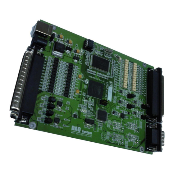
USB-AIO10
Windows, Windows2000, Windows NT, Windows XP, Windows 7 and Windows CE are trademarks of Microsoft. We
acknowledge that the trademarks or service names of all other organizations mentioned in this document as their own property.
Information furnished by DAQ system is believed to be accurate and reliable. However, no responsibility is assumed by DAQ
system for its use, nor for any infringements of patents or other rights of third parties which may result from its use. No license is
granted by implication or otherwise under any patent or copyrights of DAQ system.
The information in this document is subject to change without notice and no part of this document may be copied or
reproduced without the prior written consent.
User's Manual
Copyrights 2017 DAQ System Co., LTD. All rights reserved.
1-
-
USB-AIO10 User's Manual (Rev 1.1)
http://www.daqsystem.com
Advertisement
Table of Contents

Subscribe to Our Youtube Channel
Related Manuals for DAQ system USB-AIO10


Summary of Contents for DAQ system USB-AIO10
- Page 1 Information furnished by DAQ system is believed to be accurate and reliable. However, no responsibility is assumed by DAQ system for its use, nor for any infringements of patents or other rights of third parties which may result from its use. No license is granted by implication or otherwise under any patent or copyrights of DAQ system.
-
Page 2: Table Of Contents
USB-AIO10 User’s Manual (Rev 1.1) Contents Introduction 1.1 Function 1.2 Internal Block Diagram Product Features Installation 3.1 Package Contents 3.2 Installation Sequence Hardware Device 4.1 Reset Switch(SW1) 4.2 USB Connector(CN1) 4.3 Power Selection Connector(J1) 4.4 External Power Connector(J2) 4.5 RS-232 Connector(J16) 4.6 Digital InputㆍOutput Circuit... - Page 3 USB-AIO10 User’s Manual (Rev 1.1) Sample Program 5.1 USB Interface Sample Program 5.1 RS-232 Interface Sample Program References (Caution) ★ The board and external input/output signals of the device have to connect the common ground(Frame) to protect the board and peripheral devices.
-
Page 4: Introduction
USB-AIO10 User’s Manual (Rev 1.1) 1. Introduction USB-AIO10 is the function board to support Analog Input·Output, Digital Input·Output, USB 2.0 High Speed, RS-232 communication interface. It supports the voltage, current Input/Output mode for Analog signals, shield the Digital Interface. Basically, the board operation can use 5VDC external power, and optionally you can use USB power. -
Page 5: Product Features
USB-AIO10 User’s Manual (Rev 1.1) 2. Product Features [Table 1. Specification] List Specification External Interface Connector USB B-type Connector Output D-SUB Connector for Analog/Digital Input/ RS-232 D-SUB Connector 5VDC Power Connector Analog Input(AD) Channel : 4 Maximum Input Range : 0~+5V, 0~20mA... - Page 6 USB-AIO10 User’s Manual (Rev 1.1) output for external power supply (5VDC, over 500mA) is required. http://www.daqsystem.com...
-
Page 7: Installation
Installation CD (Driver/Manual/API/Sample Source etc.) 3.2 Installation Sequence To install USB-AIO10 board in your environment, do the following steps. The USB-AIP10 board is completely Hot-Plug and Plug & Play. Therefore, you can install it easily. The required PC operating system for the USB-AIO10 is Windows 2000 SP4 or Windows XP/7/10. - Page 8 USB-AIO10 User’s Manual (Rev 1.1) (4) If new hardware is found, Wizard will ask you to install the corresponding driver. To install the driver in the above figure, select "Browse the driver software on your computer (R)" and press the Next button. The following driver search screen will appear.
- Page 9 USB-AIO10 User’s Manual (Rev 1.1) (5) If the board that is found has the appropriate driver, click "Install this driver software" to start the installation. (6) When the installation is completed normally, the following message window appears. http://www.daqsystem.com...
- Page 10 Device Manager -> Universal Serial Bus Controller -> “DAQ System Analog Input/Output Board”] If you can see the “DAQ System USB2.0 Multi-Function Board” at Universal Serial Bus Controller, the driver installation is to have been over. (Check the red circle) Notice : After installation, you should re-boot the system for the proper operation.
-
Page 11: Hardware Device
USB-AIO10 User’s Manual (Rev 1.1) 4. Hardware Device Explains the board connectors and jumpers for interface to PC or other device. [Figure 4-1. Layout] 4.1 Reset Switch(SW1) The board initialization switch is done to reconnect USB, initialize the functional behavior. -
Page 12: Power Selection Connector(J1)
USB-AIO10 User’s Manual (Rev 1.1) 4.3 Power Selection Connector(J1) It is the jumper connector to connect power selection of board. When the jumper is “ON”, you can use USB power, when the jumper is “OFF”, you can use the external power 5VDC input from the J2 connector. -
Page 13: Digital InputㆍOutput Circuit
USB-AIO10 User’s Manual (Rev 1.1) 4.6 Digital Input·Output Circuit The digital signals consist a shielded circuit by Photo Coupler as like Fig 4-5. The Input signal consists the common input signal DIN_COM and 24 DIN signals and flow the proper current by both ends 12V/24V. - Page 14 USB-AIO10 User’s Manual (Rev 1.1) DOUT7 Digital Out 7 DOUT9 Digital Out 9 DOUT11 Digital Out 11 DOUT13 Digital Out 13 DOUT15 Digital Out 15 DOUT17 Digital Out 17 DOUT19 Digital Out 19 DOUT21 Digital Out 21 DOUT23 Digital Out 23...
-
Page 15: Input Signal Connector(J3)
USB-AIO10 User’s Manual (Rev 1.1) 4.8 Input Signal Connector(J3) It is for Analog, Digital signal input connector. J3 [DSUB-37S-RA] [Figure 4-7. J3 Input Signal Connector (Front View)] [Table 5. J3 Connector Pin-Out] Pin No. Name Description Remark DIN_COM Common Input Signal... -
Page 16: Analog Signal Selection Connector
USB-AIO10 User’s Manual (Rev 1.1) DIN14 Digital In 14 DIN16 Digital In 16 DIN18 Digital In 18 DIN20 Digital In 20 DIN22 Digital In 22 DGND Digital Ground Power AIN0_P Analog Input 0, Posiative AIN1_P Analog Input 1, Posiative AIN2_P... -
Page 17: Analog Input Mode Selection
USB-AIO10 User’s Manual (Rev 1.1) 4.9.1 Analog Input Mode Selection Analog Input Signal Voltage/Current Mode selection jumper connector location is shown in Fig 4-9, it displays the connector and corresponding channel number. Initially it is set to voltage mode. J4 – AIN0 J5 –... - Page 18 USB-AIO10 User’s Manual (Rev 1.1) 5. Sample Program DAQ system provides a sample program to make the user be familiar with the board operation and to make the program development easier. You can find the sample program in the CDROM...
- Page 19 USB-AIO10 User’s Manual (Rev 1.1) WR Pointer Display the buffer pointer of stored in the library to read from the board. 0x800000 is the number of data. RD Pointer Display the library buffer pointer to read from the application. View Scale Write a value to attenuate the level of article 19 that displayed in the graph.
- Page 20 USB-AIO10 User’s Manual (Rev 1.1) 5.2 RS-232 Interface Sample Program Must be stopped the USB interface in the program, the USB-AIO10 should be connected to the system through RS-232 cable. The power can use the USB power or external power. The execution file is “usb_aio10_app2.exe”.
- Page 21 USB-AIO10 User’s Manual (Rev 1.1) References 1. USB 2.0 System Architecture -- Don Anderson, USB SIG (www.usb.org). 2. Universal Serial Bus Specification -- Compaq/Intel/Microsoft/NEC/MindShare Inc. (Addison Wesley) 3. AN201 How to build application using APIs -- DAQ system 4. AN342 USB-AIO10 API Programming -- DAQ system http://www.daqsystem.com...
Need help?
Do you have a question about the USB-AIO10 and is the answer not in the manual?
Questions and answers