Table of Contents
Advertisement
Quick Links
NET-AIO12
User Manual
Version 1.1
ⓒ 2005 DAQ SYSTEM Co., Ltd. All rights reserved.
Microsoft® is a registered trademark; Windows®, Windows NT®, Windows XP®, Windows 7®, Windows 8®, Windows 10®
All other trademarks or intellectual property mentioned herein belongs to their respective owners.
Information furnished by DAQ SYSTEM is believed to be accurate and reliable, However, no responsibility is assumed by DAQ SYSTEM for its use, nor
for any infringements of patents or other rights of third parties which may result from its use. No license is granted by implication or otherwise under
any patent or copyrights of DAQ SYSTEM.
The information in this document is subject to change without notice and no part of this document may e copied or reproduced without the prior
written consent.
Advertisement
Table of Contents

Related Manuals for DAQ system NET-AIO12


Summary of Contents for DAQ system NET-AIO12
- Page 1 All other trademarks or intellectual property mentioned herein belongs to their respective owners. Information furnished by DAQ SYSTEM is believed to be accurate and reliable, However, no responsibility is assumed by DAQ SYSTEM for its use, nor for any infringements of patents or other rights of third parties which may result from its use. No license is granted by implication or otherwise under any patent or copyrights of DAQ SYSTEM.
-
Page 2: Table Of Contents
NET-AIO12 User’s Manual Contents 1. Summary 1-1. Function ------------------------------------------------------------------------ 1-2. Block Diagram ------------------------------------------------------------------------ 1-3. Operation Mode ------------------------------------------------------------------------ 1-3-1 Continuous Mode ----------------------------------------------------------------------- 1-3-2 Delay Mode ------------------------------------------------------------------------ 2. Features ------------------------------------------------------------------------ 3. Hardware 3-1. DSP Firmware Setup(J1) ------------------------------------------------------------------------ 3-2. USB-B Connector(CN1) ------------------------------------------------------------------------ 3-3. LED(RUN) (J4) ------------------------------------------------------------------------ 3-4. -
Page 3: Function
NET-AIO12 User’s Manual 1. Summary NET-AIO12 board is a high-performance signal processing board with analog input and digital output functions. By applying the TI TMS320C55xx DSP chip, it is possible to acquire high-speed data through the USB 2.0 interface and Ethernet interface of A/D-converted data of 6-channel analog signal. -
Page 4: Features
NET-AIO12 User’s Manual 2. Features [Table 1. NET-AIO12 Features] List Specifications Interface USB B-type Connector RJ-45 Wthernet Connector Header Pin Connector for Analog Input Header Pin Connector for Digital Input/Output 5VDC Power Connector Analog Input(ADC) Channel No. : 6 Max. Input Range : ±5V, ±10V(Software selection) Resolution : 16-bit Conversion error: within ±2.5% of input level... - Page 5 NET-AIO12 User’s Manual Components NET-AIO12 board, installation CD (including sample program)
-
Page 6: Hardware
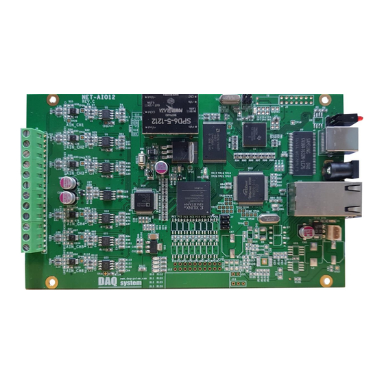
NET-AIO12 User’s Manual 3. Hardware Describes how to set board jumpers and connectors to interface equipment from a PC or other operating equipment. DSP Firmware RESET Switch Setup Jumper(J1) LED(RUN) (J4) USB-B (CN1) POWER Connector (J5) Ethernet (J10) Conn ector... -
Page 7: Usb-B Connector(Cn1)
NET-AIO12 User’s Manual 3-2 USB-B Connector (CN1) As a B-type USB connector, it is connected to a PC for data transmission/reception. 3-3 LED(RUN) (J4) Displays the operation status of the board. Lights up when data collection is in progress. 3-4 AIN Connector (J6) The analog input signal accepts a single-ended input signal in the range of ±5/10V. -
Page 8: Power Connector(J5)
NET-AIO12 User’s Manual 3-6 POWER Connector (J5) As the board power connector, input power of +5VDC, 1A or more. DC-JACK, d=2mm [Table 3. POWER Connector Description] Pin No. Pin Name Description Remark +5VDC Power 5V Power Ground 3-7 Digital Input/Output Connector (J12) Each 8-bit digital input/output signal is connected. - Page 9 NET-AIO12 User’s Manual DIN0 Digital Input 0 DOUT0 Digital Output 0 DIN1 Digital Input 1 DOUT1 Digital Output 1 DIN2 Digital Input 2 DOUT2 Digital Output 2 DIN3 Digital Input 3 DOUT3 Digital Output 3 DIN4 Digital Input 4 DOUT4...
-
Page 10: Installation
NET-AIO12 User’s Manual 4. Installation Before installing the board, check that the contents of the package are correct. 4.1 Product Contents ① NET-AIO12 Board CD (Driver/Manual/API/Sample Source etc.) ② 4.2 Driver Installation When the board is mounted, install it by referring to the CD provided with the driver and sample application program to drive the board from the PC. - Page 11 (Choose to install from a list or specific location) 예) C:\Users\why19\Desktop\NET-AIO12_Driver\x64 [Figure 6. NET-AIO12 Device search screen] The driver folder contains “net_aio10.inf” and “net_aio10.sys” files required for driver installation. (This is indicated by the name of the net_aio10 board due to compatibility with the NET-AIO10 board.)
- Page 12 NET-AIO12 User’s Manual (4) When the installation is completed normally, a message window as shown below appears.
- Page 13 NET-AIO12 User’s Manual (5) When the installation is complete, you can use the NET-AIO12 board immediately. Before using it, check if the driver has been installed normally by the following method. In My Computer -> Properties -> Device Manager screen, check whether Universal Serial Bus Controller ->...
-
Page 14: Software
NET-AIO12 User’s Manual 5. Software A standard API library is supported to access various functions of the NET-AIO12 board, and a sample program applied to it is provided to the user. 5-1 Sample Program It is a program implemented using the library and is composed as follows. - Page 15 NET-AIO12 User’s Manual Displays the number of bytes of data received from the board Data Read Rate AD data received from the board displays the number of AD Data Rate bytes Displays the library buffer storage pointer. Buffering WR Pointer Display library buffer read pointer.
- Page 16 NET-AIO12 User’s Manual device. First, the execution mode selection should be selected as USB. Retrieve the USB load image. FIND FLASH MEMORY PROGRAM Search for an executable image to be saved in flash memory. FIND EMIF.BIN(1) Loads the retrieved file image to the board memory.
-
Page 17: Appendix
NET-AIO12 User’s Manual Appendix A-1. Repair Regulations Thank you for purchasing the product of DAC System. Please refer to the following regarding customer service regulated by DAC System. (1) Read the user manual and follow the instructions before using DAC System products. - Page 18 NET-AIO12 User’s Manual MEMO Contact Point Web sit : https://www.daqsystem.com Email : postmaster@daqsystem.com...
Need help?
Do you have a question about the NET-AIO12 and is the answer not in the manual?
Questions and answers