Advertisement
Quick Links
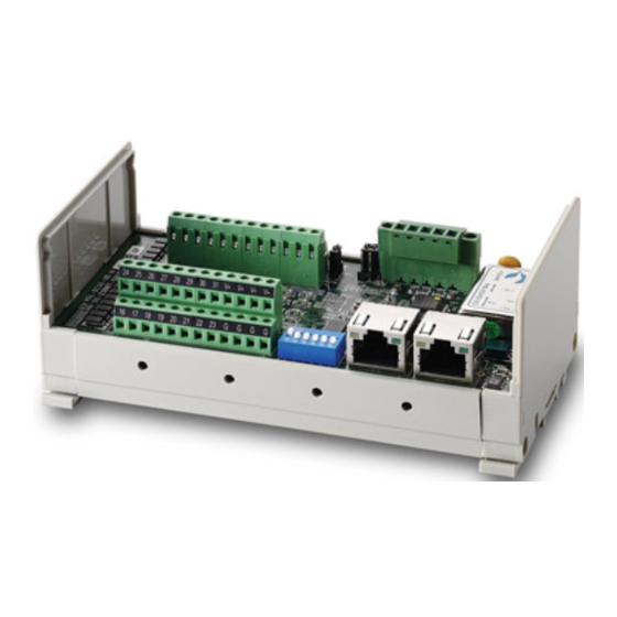
HSL-DI32
Pin Definitions
P1
No.
Name
I/O
Function
0
DI0
I
Discrete Input Channel 0
1
DI1
I
Discrete Input Channel 1
2
DI2
I
Discrete Input Channel 2
3
DI3
I
Discrete Input Channel 3
4
DI4
I
Discrete Input Channel 4
5
DI5
I
Discrete Input Channel 5
6
DI6
I
Discrete Input Channel 6
7
DI7
I
Discrete Input Channel 7
G
IO_GND
--
Digital I/O Power Ground
G
IO_GND
--
Digital I/O Power Ground
G
IO_GND
--
Digital I/O Power Ground
G
IO_GND
--
Digital I/O Power Ground
P2
No.
Name
I/O
Function
16
DI16
I
Discrete Input Channel 16
17
DI17
I
Discrete Input Channel 17
18
DI18
I
Discrete Input Channel 18
19
DI19
I
Discrete Input Channel 19
20
DI20
I
Discrete Input Channel 20
21
DI21
I
Discrete Input Channel 21
22
DI22
I
Discrete Input Channel 22
23
DI23
I
Discrete Input Channel 23
G
IO_GND
--
Digital I/O Power Ground
G
IO_GND
--
Digital I/O Power Ground
G
IO_GND
--
Digital I/O Power Ground
G
IO_GND
--
Digital I/O Power Ground
RJ1-RJ2
No.
Name
Function
1
NA
NA
2
NA
NA
3
TX+
RS-422/485 Transmission Line, Positive
4
RX-
RS-422/485 Receiving Line, Negative
5
RX+
RS-422/485 Receiving Line, Positive
6
TX-
RS-422/485 Transmission Line, Negative
7
NA
NA
8
NA
NA
POWER1
No.
Name
I/O
Function
1
EX +24V
I
External Power Supply Input (+24V DC+5%)
2
EX +24V
I
External Power Supply Input (+24V DC+5%)
3
EX_GND
--
External Power Supply Ground
4
EX_GND
--
External Power Supply Ground
5
F_GND
--
Shielding Ground
P/N 50-1Z296-1000
Quick Start Guide
HSL-DI32-UD
32CH Discrete Input Module for HSL System
No.
Name
I/O
Function
8
DI8
I
Discrete Input Channel 8
9
DI9
I
Discrete Input Channel 9
10
DI10
I
Discrete Input Channel 10
11
DI11
I
Discrete Input Channel 11
12
DI12
I
Discrete Input Channel 12
13
DI13
I
Discrete Input Channel 13
14
DI14
I
Discrete Input Channel 14
15
DI15
I
Discrete Input Channel 15
V+
IO +24V
--
Digital I/O Power
V+
IO +24V
--
Digital I/O Power
V+
IO +24V
--
Digital I/O Power
V+
IO +24V
--
Digital I/O Power
No.
Name
I/O
Function
24
DI24
I
Discrete Input Channel 24
25
DI25
I
Discrete Input Channel 25
26
DI26
I
Discrete Input Channel 26
27
DI27
I
Discrete Input Channel 27
28
DI28
I
Discrete Input Channel 28
29
DI29
I
Discrete Input Channel 29
30
DI30
I
Discrete Input Channel 30
31
DI31
I
Discrete Input Channel 31
V+
IO +24V
--
Digital I/O Power
V+
IO +24V
--
Digital I/O Power
V+
IO +24V
--
Digital I/O Power
V+
IO +24V
--
Digital I/O Power
JUMPERS
JP1(When Reset)
1-2
Clear Data (Default)
2-3
Keep Data
JP3: Terminator Resistor
1-3
ON
2-4
3-5
OFF (Default)
4-6
JP5
1-2
3-4
6M (Default)
5-6
Specifications
Number
Type
Input Current
NPN Sinking or Dry Contact
-10 mA
32
PNP Sourcing or Wet Contact +10 mA
LED Indicators: Active DC power (Red)/ Link (Green)/ Discrete Output (Yellow)
DIP Switch Settings
The DI32 occupies 2 consecutive address allocations starting from odd (switch bit 1 set to ON).
ON
1 2 3 4 5 6
Rev. 1.0
JP2: Input Mode
1-2
NPN (Default)
2-3
PNP
JP4
1-3
Full Duplex
2-4
(Default)
3-5
Half Duplex
4-6
3M
12M
Operating Voltage w/ +24 VDC
ON
OFF
11.4 VDC (min.)
14.3 VDC (max.)
12.6 VDC (min.)
9.8 VDC (max.)
ON = 1
100000
address 1, 2
110000
address 3, 4
...
...
110111
address 59, 60
101111
address 61, 62
OFF = 0
Apr. 29, 2019
Advertisement

Subscribe to Our Youtube Channel
Related Manuals for ADLINK Technology HSL-DI32-UD


Summary of Contents for ADLINK Technology HSL-DI32-UD
- Page 1 HSL-DI32 Quick Start Guide Rev. 1.0 HSL-DI32-UD 32CH Discrete Input Module for HSL System Pin Definitions JUMPERS Name Function Name Function JP1(When Reset) JP2: Input Mode Discrete Input Channel 0 Discrete Input Channel 8 Clear Data (Default) NPN (Default) Discrete Input Channel 1...
- Page 2 -P PNP Sourcing Input 71.8 4.7k -P Wet Contact Input 4.7k 52.7 Web: http://www.adlinktech.com Service: service@adlinktech.com Tel: +886-2-8226-5877 Fax: +886-2-8226-3337 Leading EDGE COMPUTING Copyright ©2019 ADLINK Technology, Inc. Contents and specifications subject to change without notice. P/N 50-1Z296-1000 Apr. 29, 2019...
Need help?
Do you have a question about the HSL-DI32-UD and is the answer not in the manual?
Questions and answers