Table of Contents
Advertisement
Quick Links
Advertisement
Table of Contents

Subscribe to Our Youtube Channel
Related Manuals for LineEye LE Series


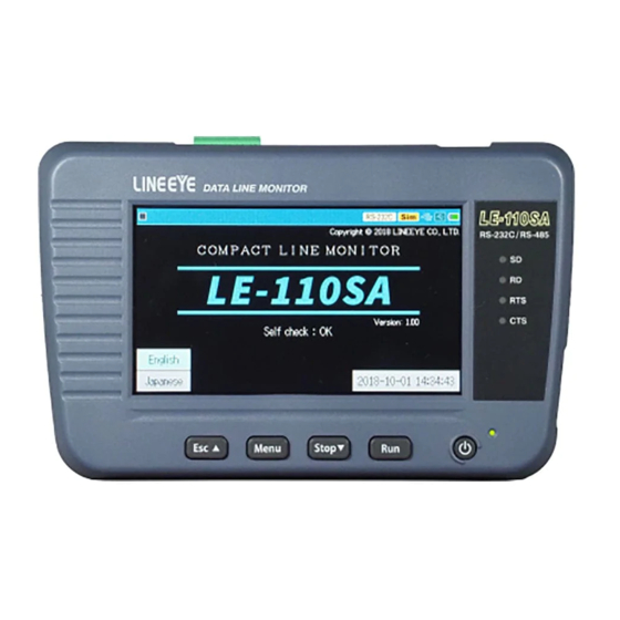
Summary of Contents for LineEye LE Series
- Page 1 DATA LINE MONITOR LE-110SA LE-120SA INSTRUCTION MANUAL 《 Ver.5 2020.10 》...
- Page 3 LINEEYE makes no warranty or guarantee, either expressed or implied with respect to its quality, performance, merchantability, or fitness for a particular purpose. LINEEYE shall not be liable for direct, in-direct, special, incidental, or consequential damages resulting from any defect in the product.
-
Page 4: Safety Information
Safety Information Read this first!! This Safety Information includes the following important information in order to not only have you learn the right way to use the line monitor, but also prevent you from causing damage to people and property. Before using, please read the main contents after you understand the following symbols &... - Page 5 Warning * Turn off the power and unplug the line monitor immediately when liquid or foreign substance gets into the line monitor. Conti nuous use may result i n ig n it ion, elect r ic shock and malfunction. * Do not touch the line monitor with wet hand. This may result in an electric shock and malfunction.
- Page 6 Caution * Do not place the line monitor in following conditions. It may cause the generation of heat, burn, electric shock, malfunction and degradation. * Magnetic filed or dusty place. Have static electricity. * Temperature or humidity is above the specification. * Temperature is changing rapidly.
- Page 7 Caution * Attention for using the USB charger. It may cause the generation of heat, burn, electric shock and malfunction. Do not use it above the specification of input. Do not use the broken one. Do not twist the cable or insert it upside down. Do not use it near the heater.
-
Page 8: Table Of Contents
CONTENTS Introduction ..................1 Safety Information ..............2 Chapter 1 Before Using the Product ...........9 1.1 Guide to This Manual ..............9 1.2 Unpacking ................... 10 1.3 Major Functions and Features ............ 11 1.4 Explanation of Each Part ............12 1.5 Power and Battery ..............14 Chapter 2 Basic Operation and Set-Up ........16 2.1 Power Source ON ............... - Page 9 Chapter 4 Connect to the Target Devices .........30 4.1 Connect to RS-232C ..............30 4.2 Connect to RS-422/RS-485(LE-110SA) ........31 4.3 Connect to TTL interface(LE-120SA) ........33 Chapter 5 Monitor Function .............34 5.1 Overview ..................34 5.2 Start and Stop Monitoring ............34 5.3 Scroll and Jump ................
- Page 10 Chapter 9 PC Link Function .............56 9.1 Installation of the USB Driver ............ 56 9.2 Installation of PC link software ..........57 9.3 Remote control ................58 9.4 Measured data display and text conversion .......60 Chapter 10 Documents .............62 10.1 Specifications ................62 10.2 Data Code Table ................64 10.3 Option ..................
-
Page 11: Chapter 1 Before Using The Product
Chapter 1 Before Using the Product 1.1 Guide to This Manual Functions of Each Model ■ This instruction manual explains functions of both LE-110SA and LE-120SA. If only one model has a specific function, the model name is printed next to the explanations of function. Screen Display Representation ■... -
Page 12: Unpacking
1.2 Unpacking When you unpack the product, make sure of the following: ■ Product has not been damaged during transport. ■ You have received all the standard accessories listed below. LE-110SA ・ Line Monitor (LE-110SA) ・ DB9 Monitor Cable (LE-009M2) ・... -
Page 13: Major Functions And Features
1.3 Major Functions and Features LE-110SA and LE-120SA are handheld data monitor which are useful to develop/test communication system and trouble shooting. LE- 110SA supports RS-232C and RS-422/485 interfaces. LE-120SA supports RS-232C and TTL (1.8/2.5/3.3/5V) interfaces. Functions ◆ On-line Monitoring Monitors communication protocol or data to check for existence of hindrance in the line, or to line monitor the communications. -
Page 14: Explanation Of Each Part
1.4 Explanation of Each Part [ LE-110SA ] 14) 13) F u n c t i o n Turn on / off the power. Power Switch Press for a while to turn off the power. [ Run ] key Start monitoring / simulating. Stop monitoring / simulating. - Page 15 [ LE-120SA ] F u n c t i o n Turn on / off the power. Power Switch Press for a while to turn off the power. [ Run ] key Start monitoring / simulating. Stop monitoring / simulating. [ St o p ] ke y Scroll data (forward).
-
Page 16: Power And Battery
1.5 Power and Battery USB Bus Power Supply power from a PC, or USB charger (option). Micro USB cable Micro USB cable USB battery charger (not included) USB port Connect attached micro USB cable to the USB device port of line monitor. Attention: Do not use the USB charge which outputs 9V or 12V. - Page 17 There is a natural discharge on the batteries. If you do not use the line monitor for a while, remove the batteries from the line monitor. We recommend charging the batteries one in a year. LINEEYE and our distributors are able to supply spare batteries. We do not warrant the batteries. -15-...
-
Page 18: Chapter 2 Basic Operation And Set-Up
Chapter 2 Basic Operation and Set-Up 2.1 Power Source ON Press the power switch and following screens will be displayed. 〔 LE-110SA 〕 〔 LE-120SA 〕 If “Self Check NG” is displayed, it is necessary to have a repairing. Press the power switch for a while to turn off the power. After a few seconds, data screen window will be displayed. -
Page 19: Data Display Window
2.3 Data Display window 6) 7) Measuring 〔 〕 , Pause 〔 〕 Position of data/ all data. Able to input the position of data. Speed and character framing while measuring (e.g. B8-PO-S1) (*1) Other status Measuring (selected) interface. Selected Mode. [Mon]: Monitoring, [Sim]:Simulating Status of USB device mode (Green: Connected) (*2) Status of Host port (Green: Connected) -
Page 20: Languages (Japanese/English)
2.4 Languages (Japanese/English) It is able to select a language (Japanese/English). Select a language from opening screen. 2.5 Date and Time Setting Set date & time in the line monitor correctly. Timestamp information will be used for the measured data and saved file names. Touch the display of date and time.(e.g. -
Page 21: Settings For Charging Batteries
LE-110SA/120SA cannot charge 100% of Ni-MH batteries. To charge them full, you need to use the Ni-MH battery charge for AA-size. LINEEYE confirms the performance of Ni-MH battery chargers: “BQ- CC23” and “BQCC55” of Panasonic. “TNHC-34SMC” and “TNHC- 34HBC” of Toshiba. -
Page 22: Adjust Lcd Back Light
2.7 Adjust LCD Back Light It is able to adjust the brightness of LCD back light. Press [Menu] → [System setting] → [Backlight brightness] and adjust the brightness using [▼] [▲] keys. While holding down [Menu], press [Run] to make the screen lighter or While holding down [Menu], press [Stop] to make the screen darker. -
Page 23: Chapter 3 Basic Settings
Chapter 3 Basic Settings 3.1 Setting Menu Press [Menu] to set basic settings. Measurement port / : Select a measurement port of line monitor and a Function function. Configuration : Select basic communication conditions. Trigger : Select trigger factors and actions. Set the timer/ counter for trigger function. -
Page 24: Measurement Port / Function
3.2 Measurement Port / Function Touch [Menu] → [Measurement port/Function]. Each one of LE-110SA and LE-120SA has two interfaces. Select an appropriate port to measure. For LE-110SA ■ Measurement Port RS-232C : Measure RS-232C port of line monitor. RS-422/485 : Measure RS-422/485 port of line monitor. ■... - Page 25 ■ Transmitting delay time Select an interval (1-99999ms) of one data when transmitting test data. ■ Repeat transmittion Mark on this to send data repeatedly. ■ Transmitting idle time Select an interval (1-99999ms) of sending data repeatedly. For low speed data below 300bps, delay time and idle time settings might not be reflected correctly.
-
Page 26: Communication Speed
3.3 Communication Speed Communication speed has to be set according to the speed of target devices. Press [Menu] → [Configuration] and set the speed. ■ Speed Touch […] and select a preset speed. If appropriate speed cannot be found in the preset speed, it is able to type any speed using [0]-[9] keys. - Page 27 ■ Character Framing Set the character framing such as data bit length, parity bit and stop bit. Data bit 7 or 8 bit Parity None, Odd, Even Stop bit 1 or 2 bit If the communication condition of target device is unknown, try to use “Auto configuration”.
-
Page 28: Frame End Setting
3.4 Frame End Setting Set the time/data of non-communication state which is recognized as a frame end. This setting is necessary to have an accurate time stamp → 3.6 Idle Time and Time Stamp Press [Menu] → [Configuration] and set [Frame end time] using numeric keys. -
Page 29: Capture Memory
3.5 Capture Memory LE-110SA/120SA has an inner memory of 16Mbyte for about 4.000K data. Each one of send/receive data, idle time, line state consumes 4byte and time stamp consumes 8byte of memory. Press [Menu] → [Record control] and set appropriate settings. ■... -
Page 30: Idle Time And Time Stamp
3.6 Idle Time and Time Stamp Idle time (non-communication time) and time stamp (frame received/ sent time) can be added along with communication data. Press [Menu] → [Record control] and set [Idle time] and [Time stamp]. ■ Idle time Idle time can be select from none, 100ms, 10ms and 1sec. -
Page 31: Line State
3.7 Line State Control lines of target devices and status of external trigger input can be added along with communication data. Press [Menu] → [Record Control] and mark on “Line State Recording”. External trigger input is displayed in the “TRG” line. Available control lines are different in each port. -
Page 32: Chapter 4 Connect To The Target Devices
Chapter 4 Connect to the Target Devices 4.1 Connect to RS-232C Set “Measurement port: RS-232C” before measuring RS-232C. → 3.2 Measurement Port / Function < RS-232C Port > Dsub 9pin male Input/Output 5Pin Signal name Pin To monitor To simulate 1Pin Signal Ground Transmission data... -
Page 33: Connect To Rs-422/Rs-485(Le-110Sa)
■ To simulate data Select “Simulation” mode and press RS-232C CABLE [Run] . RS-232C port of linemonitor will be DTE specification (equivalent RS-232C Port to COM port). Check the DTE/DCE Dsub9 specification of targetdevice and connect to the linemonitor, using straight or cross cable. - Page 34 ■ Monitor RS-422 between Device A and Device B Device A Device B LE-110SA RXD+ TXD+ TXD+ RXD- TXD- TXD- RXD+ TXD+ RXD+ RXD- TXD- RXD- We recommend connecting “TXD+” to “TXD-” and “RXD+” to “RXD-” using twisted pair cables. If your target devices have “TXDA”...
-
Page 35: Connect To Ttl Interface(Le-120Sa)
4.3 Connect to TTL interface(LE-120SA) Select an appropriate voltage level of TTL in the line monitor setting before measuring TTL (UART) signals. → 3.2 Measurement Port / Function < TTLPort > MIL box type 10pin cable Cable color Signal name Pin Input/ LE-10ES1 LE-5LS output... -
Page 36: Chapter 5 Monitor Function
Chapter 5 Monitor Function 5.1 Overview Monitor function records communication data in the capture buffer without impacting on a communication channel. Communication data is displayed with time stamp, idle time, control signals and state of external trigger at real time. As a result, error time and time out conditions can be investigated. Moreover, the trigger function, which detects specific communication conditions, and filter function for specific address frame, which makes a memory effectively used, are included. - Page 37 Measurement data is displayed in character codes (ASCII, HEX) and errors and breaks are displayed in special code. special code meaning Parity error Framing error Parity error and Framing error Break (start bit, character bit, stop bit are all zero) Over run error * 1 :...
-
Page 38: Scroll And Jump
5.3 Scroll and Jump Once the measurement ends, the latest captured data is displayed on the screen. To check the previous data, you can scroll the display or jump to a specific data. ■ Scroll Data Sw ip e you r f i nge r on t he screen to scroll data. - Page 39 ■ Marker function The measurement data position (position number) can be stored for up to 5 locations. You can jump directly to the position (mark). Touch [ ] at the bottom of the data display screen to select Set to marker “...
-
Page 40: Retrieval Function
5.4 Retrieval Function The retrieval function enables you to find specific data among the vast amount of data in the capture memory. It also enables you to count the number which satisfies a particular conditions. Setting of Retrieval Condition To u c h [ Fi n d] a n d it w i l l b e changed in green. - Page 41 Touch [Action] and select either [Display] or [Count]. Display Data which satisfies the retrieval condition is displayed at the top of the screen. Count The count, which is the number of times the retrieval condition was satisfied, is displayed. Retrieve Touch [▲] or [▼] in the right bottom to start the retrieval.
-
Page 42: Line State Display Function
5.5 Line State Display Function Line state display function can display status of control lines and external trigger input along with communication data. Recorded data without status of control lines cannot use this function. Confirm the setting of record control and measure data with state of control lines. →... -
Page 43: Display Data Per A Frame
5.6 Display Data Per a Frame Data can be displayed per a frame with a time stamp on the top to see the data clearly. → 3.6 Idle Time and Time Stamp The screen can be changed to the frame data display by touching [Change display] some times. -
Page 44: Auto Configuration Function
5.8 Auto Configuration Function Auto-Configuration is the function that automatically determines the conditions of communication through a communication channel. It is useful to measure the target devices with unknown communication conditions. This function is not 100% correct because the communication conditions of devices varies. -
Page 45: Chapter 6 Simulation Function
Chapter 6 Simulation Function 6.1 Simulation Function When you do not have communication partner for your development, the line monitor plays the role and can send/receive the data by this function. Seeing the data sent from the target device on the display of line monitor, you can send the test data by touch panel control. - Page 46 ■ Input by HEX To enter the data to be sent, touch [0] to [9] and [A] to [F] and input it in hexadecimal. The entered data is displayed by the character code set in the data code of the configuration.
- Page 47 Touch First data to move the cursor to the first data in the transmission data “ ” table. Touch “Last data” to move the cursor to the final data. Touch “Clear table” to delete all the data in the transmission data table being edited. ■...
- Page 48 ■ Selection You can copy and paste the data registered in the transmission data table. Touch “Selection” to select the data at the cursor position. T hen the cu rsor changes to a square. You can use the arrow keys to move the cursor to change the range.
-
Page 49: Start/Finish Simulation
6.3 Start/Finish Simulation Confirm settings and connection Confirm the measurement port, Simulation settings, and communication condition. Confirm the connection with the target device. → 3.2 Measurement Port / Function → 3.3 Communication Speed → Chapter 4 Connect to the Target Devices Start the Simulation Test It starts measurement by pushing [Run] and the line monitor is... - Page 50 [ Break ] Outputs the break state [ RTS ] ON/OFF of the RTS control line. [ DTR ] ON/OFF of the DTR control line. Fixed data Character code ASCII/JIS/HEX EBCDIC [ ENQ ] [ ACK ] [ NAK ] [ WACK] 10h,3Bh 10h,6Bh...
-
Page 51: Chapter 7 Trigger Function
Chapter 7 Trigger Function 7.1 Trigger Function By the trigger function the line monitor make a specific measurement cont rol action upon occur rence of a specif ic factor such as communication error while measurement. You can measure the response time by controlling timer/counter and can count how much the specific event occurred. -
Page 52: Trigger Setting
7.3 Trigger Setting You can set the 4 pairs of trigger factor and action. Push [ Menu ] and touch [Trigger ] to display trigger setting display. Touch and check the check box of the trigger you want to make valid at the start of measurement. - Page 53 ■ Line state Specify the detection logic of a control line and external trigger input TRG by 1(H), 0(L), X(Don’t Care). The status judgment of 1,0 is as same as that of the line state display. The condition meets when all the signals are set to AND condition and the condition changes from mismatch to match.
- Page 54 Trigger Action Setting Touch the setting display of trigger action and touch the trigger action to be set. ■ Buzzer Sounds the buzzer for about 0.3 second. ■ Stop measurement It automatically stops measurement after the specif ied length of measurement.
- Page 55 ■ Timer control It starts, stops, or restarts from 0 the specified timer. ■ Counter control It adds 1(increment) to or clears to 0 the specified counter. ■ Trigger control It makes the specif ied trigger factor valid, invalid, or inverts the status of it.
-
Page 56: Timer / Counter Function
■ External trigger output 2 (OT2 pulse output) It outputs an about 1m second L pulse to the external trigger output 2 (OTS2). From the trigger output 1 (OT1) it outputs about 1m second L pulse when the trigger factor meets regardless of the trigger action setting. - Page 57 ■ Transmission/Reception counter (TXD Counter / RXD Cou) action 1) It is cleared to 0 when starts measurement. 2) It increments the counter when receiving data of transmission side TXD or reception side RXD. (The max number is 4294967295.) Timer / counter setting Push [Menu] and touch [Trigger] of the setting item to display the trigger setting display, then touch...
-
Page 58: Chapter 8 Data Save And Read
Chapter 8 Data Save and Read 8.1 File Management Function You can save the measured data or setting data into a USB memory and reload it when you need it. [Attention] Do not pull off the USB flash or do not turn off the power of line monitor while it accesses the USB flash as the data and the USB flash will be broken. -
Page 59: Filter Function
By touching [OK], it starts saving and returns to file management display when it finishes saving. If the data amount to be saved surpasses the available capacity of USB memory it stops saving with an error message. You need to delete a file to make a capacity for the data saving before retry saving. -
Page 60: Reload (Read)
By reloading the current setting data and contents in the capture memory are overwritten. The LINEEYE line monitors can reload the files saved by the other LINEEYE line monitor, but some data cannot be reloaded correctly. File Name Change You cannot change the file name directly. -
Page 61: Chapter 9 Pc Link Function
1) Start WITHOUT connecting it with a PC. 2) Set the attached CD-ROM to the PC. Or download the USB driver for LE-110SA series (lewusbd_v1.1.x.x or later) from LINEEYE website and decompress it to any folder of the PC. 3) Run the “setup.exe” file. -
Page 62: Installation Of Pc Link Software
→ 9.1 Installation of the USB driver ■ How to install the PC link software 1) Download the light edition of LE-PC300R from the LINEEYE website and decompress it to any folder of the PC. 2) Run the setup.exe file in the folder. -
Page 63: Remote Control
5) I nput t he compa ny na me and the serial number at the following display. Input “LITE” to the serial number box for the light edition. You need to input a serial number when you install the product version. 6) Click “Finish”... - Page 64 By [ ] (or at Remote – Remote setting – Connection), confirm that the connection method is USB and the serial number is that of the line monitor. By [ ] (or at Measurement – Analyzer setting), set the monitor condition of the line monitor.
-
Page 65: Measured Data Display And Text Conversion
9.4 Measured data display and text conversion ■ Measured data display The saved data in the USB memory captured by line monitor can be displayed on PC. 1) Connect the USB flash which has the measured data into the USB port of PC. - Page 66 5 ) S p e c i f y t h e c o n v e r s i o n [Text file conversion example] condition and click Convert to make the converted file in the same folder. * For the detail please refer to the online help of the PC link software. -64-...
-
Page 67: Chapter 10 Documents
Chapter 10 Documents 10.1 Specifications Item LE-110SA LE-120SA Interface RS-232C,RS-422/485 RS-232C,TTL Signal level None 1.8V,2.5V,3.3V,5V Protocol ASYNC ASYNC, UART Capture memory 16Mbyte (4000Kdata). Able to divide in two. 50, 75, 150, 300, 600, 1200, 2400, 4800, 9600, 12800, Speed(bps) 14400, 19200, 28800, 38400, 57600, 115200, 230400, 460800, (* 1) User defined speed... - Page 68 Trigger action Stops measurement/test (number of offsets until a stop can be set), validates trigger conditions, controls timer (start/stop/restart), controls counter (count/clear), activates buzzer, saves monitor data on a USB flash memory, sends the specified character string (during manual simulation), and sends pulse output to external trigger terminal OT2.
-
Page 69: Data Code Table
10.2 Data Code Table ■ ASCII NU DL △ SH D1 ” EQ NK AK SY & BL EB ’ BS CN HT EM LF SB VT EC < CR GS SO RS > ~ ■ JIS NU DL △ タ... - Page 70 ■ EBCDIC NU DL DS △ & SH D1 ~ D3 WS PF RE BP PN HT NL LC BS EB NS DT PC EC ET GE CN SA S1 EM SE RT US SM RF ¢ VT C1 CP C3 MA D4 <...
-
Page 71: Chapter 11 After Support And Maintenance
Please note that by this operation measured data in the buffer memory is also all cleaned. 11.2 How to Update the Firmware The latest firmware will be available from LINEEYE website. https://www.lineeye.com/html/download_update.html Use the software for firmware update “le8firm.exe” included in the Utility folder of attached CD-ROM. - Page 72 Select USB at Con nect ion Method and select the serial number at Serial number. Then click [Next]. 5) Click [Select] and select the f i r mwa re f i le. T he n cl ick [Next]. 6 ) I t s t a r t s t r a n s f e r o f t h e firmware by clicking [Start].
-
Page 73: Troubleshooting
11.3 Troubleshooting Problem Cause / Remedy ・ Charge the battery when powered by batteries. Cannot turn on the power ・ Try another USB cable when powered by bus power. T h e p o w e r t u r n o f f ・... - Page 74 ・ As the signals of TTL port are L active and pulled- All the line state LEDs light down inside the line monitor, the LEDs light when although a target device is not you select TTL port without connecting a target connected.
-
Page 75: Warranty And After Service
LINEEYE ■ Warranty Within a period of 12 months from the date of syipment, LINEEYE warrants that your purchased products (except consumable parts such as the battery and software) are free of charge from any defects in material and workmanship, only when the products are operated in accordance with procedures described in the documents supplied by LINEEYE. - Page 76 ■ Repair after warranty period LINEEYE will repair the products at our own expense. ■ Calibration Enable to have a hardware calibration test by the line monitor After Support Read “FAQ” in our Website or email us. Please refer to “FAQ”. We also have support by email regarding the technical issue.
- Page 78 LINEEYE CO., LTD. 4F., Marufuku Bldg., 39-1, Karahashi Nishihiragaki-cho, Minami-ku, Kyoto, 601-8468, Japan Tel : 075(693)0161 Fax : 075(693)0163 URL https://www.lineeye.com Email :info@lineeye.co.jp Printed in Japan M-50112SAE/LE...
Need help?
Do you have a question about the LE Series and is the answer not in the manual?
Questions and answers