Advertisement
Quick Start Guide
Thank you for your purchase of LE-series.
This booklet tells you only the basic operation. For more detailed information, please refer
to the instruction manual (PDF) in the utility CD attached to the product.
When you unpack the product, make sure you have all following items
□
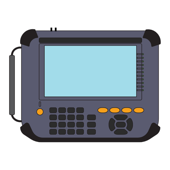
Protocol Analyzer
□
Interface Sub-board [SB-T1E] (attached to the analyzer)
□
( Already mounted)
Hand strap
□
Wide input AC adapter (Input :AC100 ~ 240V/ Output :DC9V )
□
LAN cable
□
USB cable (Type A - Type-C)
External signal I/O cable [LE-4TG]
□
□
Utility CD
Quick Start Guide ( this booklet )
□
□
Carrying bag [LEB-01]
□
Warranty
Please let us know if you find any damage to the product or accessories lacking.
2024 by LINEEYE CO., LTD. All rights reserved.
MULTI PROTOCOL ANALYZER
1
1
1
1
1
1
1
1
1
1
1
Advertisement
Table of Contents

Related Manuals for LineEye LE-8500X-SE


Summary of Contents for LineEye LE-8500X-SE
- Page 1 □ Utility CD Quick Start Guide ( this booklet ) □ □ Carrying bag [LEB-01] □ Warranty Please let us know if you find any damage to the product or accessories lacking. 2024 by LINEEYE CO., LTD. All rights reserved.
- Page 2 ・ Reference page is displayed in (Pxxx). It is prohibited to reprint or duplicate any part of this manual without prior permission of LINEEYE. The content of this manual and specification of the product is subject to change without any notice...
-
Page 3: Safety Information
Safety Information Please do not use the line monitor in the following conditions. 〔 Description of the symbol and mark 〕 Warning: There is a possibility of getting hurt, such as a death or a serious injury. Caution: There is a possibility of getting injured or damaging the product. Warning ●... - Page 4 Nomenclature Name Description AC adapter plug Connects the AC adapter, which serves as a battery charger. Power Switch Press for about 1 second to turn the power on/off. SD Card Slot The inlet for a SD/SDHC card. USB Host Port Connection port for a USB flash drive or Printer.
-
Page 5: Power Supply And Battery
< Notice for battery > ● Do not short the terminal of the battery. ● Use the battery and battery charger specified by LINEEYE. ● Do not disassemble or modify the battery. ● Do not use the analyzer near the heater or leave it in the place with high temperature. -
Page 6: Key Operation
Key operation There is a keyboard to input data and operate commands. ڦKeys Operations Function Turn ON/OFF the power. Press it for more than 1sec. [RUN] Start monitoring, measuring or testing operation. [STOP] Stop monitoring, measuring or testing operation. [MENU] Return to the top menu. -
Page 7: Initial Settings
Select the language at the first time using the analyzer. If it is selected already, it displays the top menu. Both LE-8500XR-SE and LE-8500X-SE models are displayed as “LE-8500X”. To set each configuration, touch the configuration menu or select by [▲], [▼],[ ],[ ] keys and then press... -
Page 8: Record Control
Record Control Touch “Record Control” from top menu and set the record conditions of measured data. Shortcut key [ MENU ] , [B] Touch “Capt. Buffer” on the left upper or press [SHIFT] + [ ] or [SHIFT] + [ ] ... - Page 9 To cha nge t he set t i ng of wireless LAN, touch “Set ting change” and select “station mode” or “access point mode”. LE-8500X-SE does not have the wireless function. ڧLanguage Select language from Japanese or English.
- Page 10 Functions ڦOnline Monitor Function Touch “Mode” from top menu and select “Online”. ڧConnection Connect analyzer and target devices as following. <100BASE-T1> <100BASE-T1L> Device Device Device Device PORT B PORT A PORT B PORT A PortA and PortB PortA and PortB become the fail-safe TAP.
- Page 11 Time stamp information can be synchronized with PPS signal from GPS or external Cable for PPS synchronization GPS antenna PPS device To synchronize the time stamp of 2 analyzers by a GPS active antenna, connect them as following. GPS antenna Coaxial cable for PPS synchronization ...
- Page 12 ڧOnline Monitor setting Touch “Online Opt.”. Set the resolution and time stamp. Shortcut key [ MENU ] ,[3] ڧStart and Stop measurement Press [RUN] to start monitoring. Measured data is displayed at real time and recorded in the capture memory. Press [STOP] to finish measuring.
- Page 13 Data packet is missing. “OVERRUN” is displayed. ڧDetailed display Display the details of the frame, which is displayed on the top of the Frame Display. Press [ENTER] to change the display to frame display. Refer to specification of each protocol for more details. ・...
- Page 14 B. PD(Powered Device) PSE(Power Sourcing Equipment) PORT B PORT A ڧCalibration LINEEYE recommends having the zero calibration when using the analyzer for the first time. ڧPoDL Setup Touch “PoDL Opt.”. Set the specification of PoDL and recording cycle.
- Page 15 ڧStart and End measuring Press [RUN] to start selected function, and [STOP] to end measuring. ڧResult PoDL display, dump display and graph are changeable. While PoDL and on-line monitor are measuring at the same time, touch “Online” to go back to LAN frame display.
- Page 16 ڦStatistic Function Touch “Mode” at top menu and select “Trend”. ڧConnection Connect the target network to the port A/B of analyzer. Refer to the manual of “Connection” for On-line monitor function → 「 Online Monitor Function 」 (P8) ...
- Page 17 ڦPacket Generator Function Touch “Mode” at top menu and select “PG” ڧConnection Connect the target device and analyzer as following. PORT A (PORT B for 10BASE-T1S) ڧPG setting Touch “ PG Opt.” and set the transmission packets and conditions. ...
- Page 18 ・ Edit protocol Select the protocol type from Ethernet, IPv4, ARP, ICMP, TCP, U DP and set the appropr iate header following the specification of each protocol. Tou ch “A p ply ” t o a p ply t h e setting and return to the data send table.
- Page 19 ڦPing Function Touch “Mode” at top menu and select “Ping”. ڧConnection Connect the target device and analyzer as following. PORT A (PORT B for 10BASE-T1S) ڧPing Setup Touch “ Ping Opt.”. Set the send address and interval. ...
- Page 20 ڦPLCA Examination function Tap “Mode” from top menu and then select “PLCA”. ڧConnection Insert the analyzer in the PLCA communications. (Set “OFF” the terminal control of analyzer.) Connect the cable to the PORT B of the analyzer. Device Device Device Device...
- Page 21 ڦPSE Examination Tap “Mode” from top menu and select “PSE”. ڧConnection Connect the target PSE device to the PORT A of analyzer. PORT A PORT A 10BASE-T1L 100BASE-T1 ڧPSE setting Tap “PSE Opt.” for top Menu. Set the class and state group of the target device. ...
-
Page 22: Useful Functions
Useful Functions ڦFilter function Filter function captures specific frames measured by on-line monitor function. It is able set 2 filters for port A-B Touch “Filter” from on-line monitor function. [ MENU ] ,[0] Shortcut key ڧMode If selecting “Common”, the setting on Tx is applied on Rx as well. - Page 23 ڧExample of trigger When TCP communication is captured from “192.168.1.5” to “192.168.1.8”, it stops measuring. ڦSave and Load of the Data An SD/SDHC card or USB flash drive can be used as a storage device, and measurement data and setting data can be saved to it. Tap “File Manager”...
- Page 24 ڦAuto Save Auto save function saves measured log f iles in the SD card or USB me mo r y a ut om at ic a l ly wh i le it continues measuring. It is useful to find a problem which rarely happens. Touch “Record Control”...
- Page 25 ڦAuto back-up function Captured data will be deleted when it turns off the power of analyzer. As a factory setting, measured data (latest 16M byte of data) will be saved in the inner eMMC automatically. To save all measured data or to delete all data, change the setting of Auto back-up. Auto Backup :...
- Page 26 Measurable Interface Expansion By using the option for measu rement expansion, you can expand the communication target to be measured. ڦExchange the board Remove the standard interface sub board and replace it with the optional interface sub board. ڦFirmware If the version of the firmware installed on the main unit is old and does not support the installed measurement expansion option, it will start in firmware update mode.
-
Page 27: Pc Link Function
PC Link Function Using the attached utility software, you can perform remote operation while displaying the screen of the analyzer, transfer online monitored data to a PC, and convert it to Wireshark format. Connect the analyzer to a computer via USB, LAN or Wi-Fi (supported models only). - Page 28 Specifications of Function and Hardware Item 2 Pole terminal block x4 (2 for 100ABSE-T1, 2 for 10BASE-T1L/T1S) 10BASE-T1S only Interface supports half duplex . Capacity: 1G byte Capture memory ( 96 ~ 10,560 byte for 1 frame, 64 byte for 1 PoDL data ) On-line Monitor Real-time display of LAN flowing between ports A and B Function...
- Page 29 4-pin for trigger function External I/O terminal SMA( female ) connector GPS Antenna Connector SMA( female ) connector PPS Signal Connector IEEE802.11b/g/n. Frequency range: 2412MHz ~ 2484 MHz Wi-Fi interface ・ Transmission power 802.11b: +18.5dBm 802.11g: +18.0dBm 802.11n: +17.0dBm Measurement data can be output to printer.
- Page 30 Memo...
- Page 32 For any technical issues Read “FAQ” in our website or email us. https://www.lineeye.com/html/contactus.html LINEEYE CO., LTD 4F., Marufuku Bldg., 39-1, Karahashi Nishihiragaki-cho, Minami-ku, Kyoto, 601-8468, Japan Tel : 075(693)0161 Fax:075(693)0163 URL https://www.lineeye.com Email : info@lineeye.co.jp Printed in Japan M-1485XSEQE/LE...
Need help?
Do you have a question about the LE-8500X-SE and is the answer not in the manual?
Questions and answers