VeriFone P630 Installation Manual
Hide thumbs
Also See for P630:
- Installation manual (56 pages) ,
- Installation manual (41 pages) ,
- Installation manual (37 pages)
Table of Contents
Advertisement
Quick Links
Advertisement
Table of Contents

Related Manuals for VeriFone P630


Summary of Contents for VeriFone P630
- Page 1 P630 Installation Guide Verifone Part Number DOC560-333-EN-B, Revision B...
- Page 2 Verifone, Inc. The information contained in this document is subject to change without notice. Although Verifone has attempted to ensure the accuracy of the contents of this document, this document may include errors or omissions. The examples and sample programs are for illustration only and may not be suited for your purpose.
-
Page 3: Table Of Contents
Cable Connections ..........17 Attaching a Cable Connector to the P630......17 Connection to Another Verifone Terminal. - Page 4 Caution and Warning Messages ........41 P P EN DI X P630 I NSTALLATION...
-
Page 5: Preface
This guide is organized as follows: Chapter 1, Overview. Provides an overview of the P630 device. Chapter 2, Setup. Explains how to set up and install the P630 device, select a location and establish a connection with other devices. Chapter 3, Specifications. Discusses power requirements and dimensions of the P630 device. -
Page 6: Conventions And Acronyms
NOTE The pencil icon is used to RS-232-type devices do not work highlight important information. on the P630 communication port. CAUTION The caution symbol indicates The unit is not waterproof or hardware or software failure, or dustproof and is intended for loss of data. - Page 7 (continued) Acronym Definitions Local Area Network Liquid Crystal Display Light-Emitting Diode PIN Entry Device Personal Identification Number Point-of-Sale RS-232 Recommend Standard number 232 Secure Access Module Trans Flash Underwriters Laboratories Universal Serial Bus Verifone Part Number P630 I NSTALLATION UIDE...
- Page 8 REFACE Conventions and Acronyms THIS PAGE IS INTENTIONALLY LEFT BL ANK P630 I NSTALLATION UIDE...
-
Page 9: Overview Features And Benefits
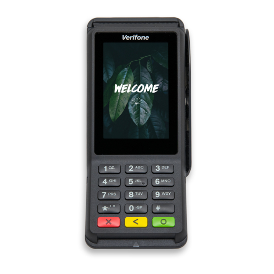
The P630 device is a consumer-facing handheld device. It can also be fix- mounted in integrated retail scenarios. The product’s design is equally appealing as a handheld PINpad and robust enough to look and function appropriately in a fixed mount setting. -
Page 10: Back Functions
Supports telco-style format • Dual-function Backspace/Clear key • Customer-entry for Cancel and Enter keys Back Functions The rear of the P630 device shows the following: • Cable connector compartment. • Threaded grommets for attaching the mounting plate. • A dual-stack (uSD+2SAMs) is built into the back of the unit to support stored- value card programs or other merchant card requirements. -
Page 11: Contactless Capability
Accepts EMV, NFC and mag-stripe contactless payments as well as PIN based transactions. Wireless • Bluetooth: Communication • Supports BT v4.2 LE Capability • WLAN: • Supports 2.4GHz/5.0GHz frequency band • Supports 802.11 a/b/g/n up to 150Mbps • Supports AP mode P630 I NSTALLATION UIDE... - Page 12 VERVIEW Features and Benefits THIS PAGE IS INTENTIONALLY LEFT BL ANK P630 I NSTALLATION UIDE...
-
Page 13: Setup Device Location
HAPTER Setup This chapter describes the setup procedure for the P630 in the following sections: • Device Location • PIN Protection Measures • Inside the Shipping Carton • SAM/TF Cards • Power Supply • Cable Connections • Smart Card Reader •... -
Page 14: Contactless Considerations
PED and cameras next in the queue Countertop No action Install so that No action Do not install with stand needed customer is needed within view of between PED and cameras next in the queue P630 I NSTALLATION UIDE... -
Page 15: Ensuring User Privacy
ETUP Inside the Shipping Carton Verifone also recommends instructions to the cardholder regarding safe PIN- entry. This can be done with a combination of: • Signage on the PED • Prompts on the display, possibly with a click-through screen •... -
Page 16: Installing Or Changing Sam/Tf Card
Not all configurations and device contexts require the use of a power supply – Verifone ships power supply with the terminal as required. Contact your Verifone representative if you have changed the context in which the terminal is used or have questions about which power supply should be used. -
Page 17: Cable Connections
Refer to the controlling device instructions for any terminal-specific warnings. Attaching a Cable The cables first have to be attached to the P630. To attach a cable to the terminal, Connector to the follow steps: P630 Step 1: Release the screw. -
Page 18: Connection To Another Verifone Terminal
V200c. Connect the 28-pin connector of the coiled serial cable (Connected to MOD 10 port, cable VPN - CBL435-002-01-A) to P630, then insert the other end of the cable to the multi-communication port of V200c. Figure 4 Connecting to P630 via Serial Connection •... - Page 19 ETUP Cable Connections Figure 5 Connecting P630 to an External Device P630 I NSTALLATION UIDE...
-
Page 20: Rs-232 Connection Using An External Power Brick
ETUP Cable Connections RS-232 Connection A special dongle cable is used, where one end of the cable plugs into the P630 Using an External while the other end terminates into the DB-9 connector housing. On the housing, Power Brick a DC jack is provided to connect to an external power brick. This is a generic... -
Page 21: Smart Card Reader
Available Connections on the External Power Brick Smart Card The smart card transaction procedure can vary depending on the application. Reader Verify the proper procedure with your application provider before performing a smart card transaction. Figure 8 Using the Smart Card Reader P630 I NSTALLATION UIDE... -
Page 22: Magnetic Stripe Card Reader Use
Leave the smart card in the card reader until the transaction is completed. Premature removal can void the transaction. Magnetic Stripe The P630 has a magnetic card reader that uses a triple-track stripe reader. This Card Reader Use gives the unit greater reliability over a wide range of swipe speeds and operating environments. -
Page 23: Optional Accessories
Once the hooks are in place, gently push down on the privacy shield until it snaps into place. Mounting Plate This accessory is used to mount P630 to vertical or inclined surfaces. To attach a mounting plate to P630: Attaching a Mounting... - Page 24 ETUP Optional Accessories Attach three M3 screws (not included in the P630 package) to the desired surface. Make sure that they are aligned with the slots on top and at the bottom of the mounting plate. Secure the terminal with the mounting plate in place by aligning the holes to the M3 screws and then sliding the entire assembly into place.
-
Page 25: External Camera
To mount the external semi-integrated camera for QR, Barcode, and OCR scanning: Release the screw and Slide out the cable cover. Attach the Data and Power cable to the terminal. Place the cable cover which has the camera holder and fix the screw. P630 I NSTALLATION UIDE... -
Page 26: Periodic Inspection
Periodically inspect the terminal for possible tampering. Signs of tampering may Inspection include: • Wires that are protruding from the device. • Foreign objects inserted into the smart card or mag stripe slot. • Signs of damage to the tamper-evident label. P630 I NSTALLATION UIDE... - Page 27 If any device is found in a tampered state, please remove it immediately from NOTE service. Keep it available for potential forensic investigation and notify your company security officer and your local Verifone representative or service provider. For more information on contacting Verifone, refer to Service and Support section. P630 I NSTALLATION...
- Page 28 ETUP Periodic Inspection THIS PAGE IS INTENTIONALLY LEFT BL ANK P630 I NSTALLATION UIDE...
-
Page 29: Hapter
HAPTER Specifications This chapter discusses power requirements, dimensions and other specifications of the P630 device. Unit Power P630 device has the following power requirements: Requirements • 110V - 240V AC, 1A Full capabilities: Temperature • 0° to 45°C (32° to 113° F) Operating temperature: •... -
Page 30: Sam Card Reader
PECIFICATIONS SAM Card Reader SAM Card • Two Security Access Modules (SAMs) Reader Security • 3DES and AES • PCI PTS 6.x approved P630 I NSTALLATION UIDE... -
Page 31: Hapter
HAPTER Maintenance and Cleaning The P630 device has no user-maintainable parts. It can, however, be cleaned. General Care Your device is a product of superior design and craftsmanship and should be treated with care. The following suggestions will help you protect your warranty coverage. -
Page 32: Additional Safety Information
If the unit shows no presence of foreign objects, test the SCR function and record results. Proceed to Step Send your device to a Verifone authorized repair center if foreign objects are CAUTION found in the SCR at any time during SCR inspection, test diagnostics, or cleaning process. -
Page 33: Magnetic Stripe Cleaning
If using a commercially available cleaning card use ONLY an approved MSR NOTE cleaning card made specifically for POS MSR Card reader devices or Petroleum MSR card readers. Decommissioning/ The decommissioning procedure applies to P630 series PCI PTS version 6.x POI- Removal from approved devices. Service NOTE Failure to use this decommission procedure causes non-compliance to the PCI PTS POI Modular Security Requirements version 6.0 approval of the device. - Page 34 AINTENANCE AND LEANING Additional Safety Information THIS PAGE IS INTENTIONALLY LEFT BL ANK P630 I NSTALLATION UIDE...
-
Page 35: Hapter
NOTE For international customers, please contact your local Verifone representative for assistance with your service, return, or replacement. Get the following information from the printed labels at the back of each P630 to be returned: • Product ID, including the model and part number. For example, “P630” and “M560 XXX-XXX-XXX.”... -
Page 36: Accessories And Documentation
• Reference the model and part number in the Note box. NOTE One MRA number must be issued for each P630 you return to Verifone, even if you are returning several of the same models. Describe the problem(s). Provide the shipping address where the repaired or replacement unit must be returned. -
Page 37: Stylus Pen
PWR435-101-04-A DC power pack (Australia) Stylus Pen PPL435-010-01-A Stylus Holder PPL435-008-01-A Cleaning Kit 02746-01 Verifone Cleaning Kit Documentation DOC560-111-EN P630 Certifications and Regulations DOC560-222-EN P630 Quick Installation Guide External Camera ACC000-100-01-A Camera Door PPL560-523-01-A Camera Cable MSC560-180-01-A P630 I NSTALLATION... - Page 38 ERVICE AND UPPORT Accessories and Documentation THIS PAGE IS INTENTIONALLY LEFT BL ANK P630 I NSTALLATION UIDE...
-
Page 39: Troubleshooting Guidelines
HAPTER Troubleshooting Guidelines This chapter lists typical malfunctions that may occur while operating a P630 device and the appropriate corrective action. If the problem persists – even after performing the outlined guidelines, or if the problem is not described, contact your local Verifone representative for assistance. - Page 40 ROUBLESHOOTING UIDELINES Transactions Fail to Process • If the problem persists, contact your local Verifone representative. Check Smart Card Reader • Perform a test transaction using several different smart cards to ensure the problem is not a defective card. •...
-
Page 41: A P P En Di X A Caution And Warning Messages
à la poussière peut annuler la garantie. Caution Setup page 14 Using an enclosed metal L'utilisation d'un cadre frame or mount may métallique fermé ou de negatively affect montage peut affecter contactless négativement contact performance. performance. P630 I NSTALLATION UIDE... - Page 42 Cet appareil est un product and any produit sûr et toute tampering can cause it to manipulation peut cease to function or l'amener à cesser de operate in an unsecured fonctionner ou manner. fonctionner de manière non sécurisée. P630 I NSTALLATION UIDE...
- Page 43 Verifone votre représentant representative or service Verifone ou prestataire provider. de services. Caution Setup page 16 Observe standard Respecter les precautions in handling précautions standard...
- Page 44 Always apply the de nettoyage ou cleaner to a cloth before d'autres solutions cleaning the device. directement sur le clavier ou l'écran. Toujours appliquer le nettoyant sur un chiffon avant de nettoyer l'appareil. P630 I NSTALLATION UIDE...
- Page 45 Caution and Warning Messages THIS PAGE IS INTENTIONALLY LEFT BL ANK P630 I NSTALLATION UIDE...
- Page 46 Verifone, Inc. 1-800-Verifone www.verifone.com P630 Installation Guide Verifone Part Number DOC560-333-EN-B, Revision B...
Need help?
Do you have a question about the P630 and is the answer not in the manual?
Questions and answers