Table of Contents
Advertisement
Quick Links
8-Port Gigabit Ethernet Switch
(4-Port PoE+) - Managed
IES81GPOEW
FR: Guide de l'utilisateur - fr.startech.com
DE: Bedienungsanleitung - de.startech.com
ES: Guía del usuario - es.startech.com
NL: Gebruiksaanwijzing - nl.startech.com
PT: Guia do usuário - pt.startech.com
IT: Guida per l'uso - it.startech.com
JP: 取扱説明書 - jp.startech.com
For the latest information, technical specifications, and support for
this product, please visit www.StarTech.com/IES81GPOEW.
Manual Revision: 11/13/2018
*actual product may vary from photos
Advertisement
Table of Contents

Related Manuals for StarTech.com IES81GPOEW


Summary of Contents for StarTech.com IES81GPOEW
- Page 1 8-Port Gigabit Ethernet Switch (4-Port PoE+) - Managed IES81GPOEW *actual product may vary from photos FR: Guide de l’utilisateur - fr.startech.com DE: Bedienungsanleitung - de.startech.com ES: Guía del usuario - es.startech.com NL: Gebruiksaanwijzing - nl.startech.com PT: Guia do usuário - pt.startech.com IT: Guida per l’uso - it.startech.com...
- Page 2 StarTech.com. Where they occur these references are for illustrative purposes only and do not represent an endorsement of a product or service by StarTech.com, or an endorsement of the product(s) to which this manual applies by the third-party company in question.
-
Page 3: Table Of Contents
Table of Contents Product Diagram ..................1 Front View ..............................1 Back View ..............................1 Package Contents ............................. 2 Requirements ............................. 2 About the LED Indicators ..............3 Wire the Power Inputs ................5 Reboot the Network Switch..............5 Reset to the Default Factory Settings ..........5 Installation ....................6 Install the Network Switch onto a Wall.................... - Page 4 Editing System Parameters ........................13 Viewing System Information ......................... 13 IP Configurations ..................13 Apply Changes and Set IP Address Settings ................... 14 Viewing IP Address Settings ........................14 Applying Changes and Setting IPv6 Address Settings ..............15 Viewing IPv6 Settings ..........................15 User Configuration .................16 Adding a New User ...........................
- Page 5 Adding an SNMP Entry ..........................25 Viewing an SNMP Table Status ......................26 Deleting an SNMP Entry ......................... 26 SNMP Access Group ................27 Adding an SNMP Access Group ......................27 Deleting an SNMP Access Group ......................27 Viewing Access Group Status ....................... 28 SNMP Community ..................28 Adding SNMP Community Settings ....................
- Page 6 Adding Port Configuration ........................34 Viewing a Port's Status ..........................35 Editing a Ports Description ........................36 Port Counters ............................. 36 Viewing Port Counters ..........................36 Viewing Port Fiber Status ........................39 Viewing SFP Module Detail Status ...................... 40 Bandwidth Utilization ................40 Viewing Port Utilization ..........................
- Page 7 Viewing LAG Port Status ......................... 50 Configuring LACP System Priority Settings ..................50 Configuring LACP Port Setting ......................50 Viewing LACP Port Information ......................51 Viewing LAG Status ..........................51 Viewing LACP Information ........................51 VLAN ......................52 Re-Assigning a VLAN ID.......................... 56 Viewing the Status of the Management VLAN ID ................
- Page 8 Spanning Tree Protocol ........................... 67 STP Global Settings ..........................71 Applying Changes to STP Global Settings ..................72 Viewing STP Information ........................72 Applying Changes to STP Port Setting ....................73 Viewing STP Port Status ......................... 75 Applying Changes to CIST Instance Information Settings ............75 Viewing CIST Instance Information ....................
- Page 9 Adding an IGMP Static Group: ......................84 Adding Additional Ports to an IGMP Static Group ................ 84 Viewing IGMP Static Group Information................... 84 Editing IGMP Static Group Information .................... 84 Viewing IGMP Group Table Information ................... 85 IGMP Router ...................85 Adding a Router Port ..........................
- Page 10 Configuring TACACS+ Server Session Parameters ................ 96 Adding a New TACACS+ Server ......................96 Editing/Deleting a TACACS+ Server Authentication List ............96 AAA ......................97 Configuring AAA on the Managed Switch: ..................98 DHCP Snooping ..................98 Applying DHCP Snooping Setting ...................... 100 Viewing DHCP Snooping Informations .....................
- Page 11 Configuring Dynamic ARP Inspection Settings ................107 Viewing DAI Informations ........................108 Configuring Dynamic VLAN Settings ....................108 Viewing DAI VLAN Setting ........................108 Configuring DAI Port Settings: ......................108 Viewing DAI Port Setting ........................109 Clearing/Refreshing the Dynamic ARP Inspection Statistics ............ 109 Configuring ARP Rate Limit Setting ....................
- Page 12 Deleting an ACL List ..........................120 Adding MAC Based ACE .......................... 120 Viewing MAC-Based ACE ........................121 Editing/Deleting a MAC based ACL Entry ..................122 Adding an IPv4 Based ACL List ......................122 Viewing IPv4 Based ACL Table ......................122 Deleting an IPv4 Based ACL List ......................
- Page 13 MED Network Policy ................139 Setting the LLDP MED Policy for Voice Application ..............139 Applying Network Policy Configuration ................... 139 Viewing LLDP MED Network Policy Table ..................140 Deleting an LLDP MED Network Policy Table Entry ..............140 Applying Port LLDP MED Configuration ................... 141 Viewing LLDP MED Port Setting Table ....................
- Page 14 Viewing RMON History ..........................153 Deleting an RMON History Entry ......................154 Applying the RMON History Index...................... 154 Power over Ethernet ................154 System Configuration ..........................154 Power over Ethernet Configuration....................155 PoE Configuration ............................ 155 Making Changes to the Power over Ethernet Configuration ............ 155 Making Changes to Power Allocation ....................
- Page 15 Warranty information ................164 Instruction Manual xiii...
-
Page 16: Product Diagram
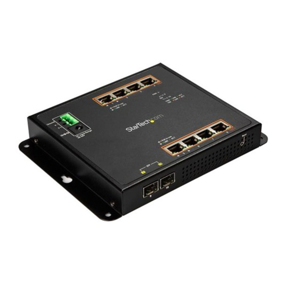
Product Diagram Front View RJ45 Ports 1 - 4 Mounting Hole Mounting Hole 3-pin Terminal Block Power LED DC Power SFP link and Input activity LEDs Link/ Activity LEDs Mounting Hole Mounting Hole RJ45 Ports 5 to 8 Back View Reset button SFP ports (dust covers installed) -
Page 17: Package Contents
1 x quick-start guide • Requirements Ethernet port connection • RJ45 network cables • This network switch is OS independent and doesn’t require any additional drivers or software. Requirements are subject to change. For the latest requirements, please visit www.StarTech.com/IES81GPOEW. Instruction manual... -
Page 18: About The Led Indicators
About the LED Indicators This network switch features a Link and Activity LED Indicator for each of the eight RJ45 ports. There is also a Power LED located above the 3-Pin Terminal Block, and a PoE Power Usage LED that illuminates in 30 watt increments. For more information about what the LED indicators signify, see the table below. -
Page 19: Wire The Power Inputs
Wire the Power Inputs You can use either an external power adapter or the terminal block to power the network switch. Alternatively, you can connect both an external power adapter and the terminal block to create a redundant power input. Note: You should use wire ranging in size of 12 to 24 AWG. -
Page 20: Installation
Installation Install the Network Switch onto a Wall The mounting holes on the network switch are 8 mm in diameter, and the distance between the two holes is 133 mm. Hold the network switch against the wall in the area that you want to install it, and use a pencil to trace the location of the four Mounting Holes onto the wall. -
Page 21: Install The Switch Onto A Magnetic Surface
To power the switch, connect an external power adapter, wire the power inputs, or do both. Connect RJ45 Cables to the RJ45 Ports on the network switch. Install the Switch onto a Magnetic Surface Push each of the Attaching Pins into a Locking Pin. Insert the Attaching and Locking Pins into one of the Mounting Holes on the network switch, through a Washer, and into a Magnet. -
Page 22: Mount The Switch Onto A Din Rail
Attach the network switch to a magnetic surface. To power the switch, connect an external power adapter, wire the power inputs, or do both. Connect RJ45 Cables to the RJ45 Ports on the enclosure. Mount the Switch onto a DIN Rail With the flat side of the DIN Rail positioned against the network switch, line up the holes on the DIN Rail with the holes on the switch. -
Page 23: About The Web-Based Gui
About the Web-Based GUI This switch can be managed using it’s web-based Graphical User Interface (GUI). You can access the GUI through any device that’s connected to your network and equipped with a standard browser (e.g. Microsoft Internet Explorer, Google Chrome, etc.). -
Page 24: Web-Based Gui Operation
Web-Based GUI Operation This section outlines how to navigate the various sections of the web-based GUI and how to adjust the configuration settings. Navigation Menu The Navigation menu features several sections that can be accessed from anywhere within the web GUI and enable access to different features including Configuration Settings, Hardware Operation, and Port Status. -
Page 25: Navigation Menu
• Home Page The Home page is the first page displayed upon login. It lists the product information and SKU and provides StarTech.com contact information. Accessing the Configuration Manager The Configuration Manager enables you to save the Running, Startup and Backup configurations. -
Page 26: System Menu
On the Save Configuration page, select a configuration option for: Source File: The running configuration. • Running Configuration: is the configuration sequence that’s been most • recently set to the switch. It’s stored in the switch's RAM as running-config and will be lost upon reboot. The running configuration file can be saved from the switches RAM to the switch's flash memory, so that the running configuration can become the startup configuration. -
Page 27: Editing System Parameters
Editing System Parameters On the System Information page, click on the Edit button next to the system parameter you wish to edit. System Name: Enter a name for the system switch. • System Location: Enter a Location. • System Contact: Enter a system contact. •... -
Page 28: Apply Changes And Set Ip Address Settings
Apply Changes and Set IP Address Settings On the IP Address Setting page, enter the following IP address settings: Mode: Indicates and gives you the option to change the IP address mode • operation. Static: Enables Static IP address operations. If Static is selected you will •... -
Page 29: Applying Changes And Setting Ipv6 Address Settings
Applying Changes and Setting IPv6 Address Settings The IPv6 Configuration page enables you to view or edit Internet Protocol (IPv6) settings such as auto configuration, IPv6 address and gateway. On the IP Address Setting page, enter the following IP address settings: Auto Configuration: Enables IPv6 auto-configuration. -
Page 30: User Configuration
DHCPv6 Client: Displays the current DHCPv6 client status. • User Configuration The User Configuration page enables you to view and delete users accounts and define, the new user account attributes such as privilege types and passwords. Adding a New User On the New User page, enter the following user information: Username: The name identifying the user. -
Page 31: Deleting A User Account
Username: Displays the user name. • Password Type: Displays the password type. • Privilege Type: Display the privilege type. • Privilege Value: Displays the privilege value. • Deleting a User Account On the Local User page, click the Delete button on the Modify field next to •... -
Page 32: Viewing System Time Information
Daylight Saving Time: Enables the clock to automatically adjust in • accordance to Daylight Saving Time. Select Disable to prevent the clock from changing. Select Recurring to configure the auto adjustment to repeat every year. Select Non-Recurring to configure the adjustment to occur once. -
Page 33: Adjusting Sntp Server Settings
Adjusting SNTP Server Settings You can use SNTP server settings to sync the switch's date and time settings to an external SNTP Server provider. On the SNTP Server Settings page, enter the following information: SNTP Server Address: Enables you to enter the IP address or domain of the •... -
Page 34: Log Management
Log Management Log Management enables you to configure and limit system messages that are logged to Flash or RAM memory. The default is for event levels 0 to 3 to be logged to flash and levels 0 to 6 to be logged to RAM. The following table lists the event levels of the switch: Level Severity Name... -
Page 35: Viewing Logging Service Status
Viewing Logging Service Status To view the current status of the Logging Service system. On the Logging Information page, the Information Value field is show you • the current state of the Logging Service (enabled or disabled). Creating/Editing a Log When adding a new log you must first enable Logging Service on the switch. -
Page 36: Remote Syslog
Remote Syslog The Remote Syslog page enables you to configure the logging of messages that are sent to syslog servers or other management stations. Sending a Message to Syslog On the Remote Logging Setting page, enter the following information: Server Address: Provide the remote syslog IP address of the switch. •... -
Page 37: Viewing The Syslog Page
Viewing the Syslog Page The Switch's Log overview is listed on this page. From the log overview you can filter logged items on a defined criteria. On the Logging Filter Select page, enter the following information: Target: The target of the local log entry. The following target types are •... -
Page 38: Clearing/Refreshing The Syslog Page
Clearing/Refreshing the Syslog Page On the Logging Messages page, you can clear/refresh the following log information: No.: Displays the number for logs. • Timestamp: Displays the time of log. • Category: Displays the category type. • Severity: Displays the severity type. •... -
Page 39: Enabling/Disabling Snmp
Network-management protocol: A management protocol is used to convey • management information between agents and NMSs. SNMP is the Internet community’s de facto standard management protocol. SNMP operations SNMP itself is a simple request/response protocol. NMS’s can send multiple requests without receiving a response. Get: Allows the NMS to retrieve an object instance from the agent. -
Page 40: Viewing An Snmp Table Status
On the View Table Setting page, enter the following information: View Name: A string identifying the view name that this entry should • belong to. The allowed string length is 1 to 16. Subtree OID: The OID defining the root of the subtree to add to the named •... -
Page 41: Snmp Access Group
SNMP Access Group On this page you can configure SNMPv3 Access Group table. The entry index keys are Group Name, Security Model and Security Level. Adding an SNMP Access Group On the Access Group Setting page, enter the following information: Group Name: A string identifying the group name that this entry should •... -
Page 42: Viewing Access Group Status
selecting the Delete button under the Action field, next to the access group you wish to delete from the Switch Viewing Access Group Status On the Access Group Status page, the following access group information will be displayed: Group Name: Displays the current SNMP access group name. •... -
Page 43: Viewing Snmp Community Settings
Click the Add button to add the SNMP Community settings. Viewing SNMP Community Settings On the Community Setting page, the following access group information will • be displayed: Community Name - Displays the current community type. • Group Name - Displays the current SNMP access group’s name. •... -
Page 44: Viewing An Snmp User
None: No authentication protocol. • MD5: An optional flag to indicate that this user is using MD5 • authentication protocol. SHA: An optional flag to indicate that this user is using SHA • authentication protocol. Authentication Password: Is a string identifying the authentication pass •... -
Page 45: Adding Snmpv1 And 2 Notification Recipients
Adding SNMPv1 and 2 Notification Recipients On the SNMPv1, 2 Host Setting page, enter the following information: Server Address: Indicates the SNMP trap destination address. It allows a • valid IP address in dotted decimal notation (‘x.y.z.w’). It can also represent a legally valid IPv4 address. -
Page 46: Viewing Snmpv1 And 2 Notification Recipients
UDP Port: Indicates the SNMP trap destination port. SNMP Agent will send • an SNMP message via this port, the port range is 1~65535. Time Out: Indicates the SNMP trap inform time-out. The allowed range is 1 • to 300. Retries: Indicates the SNMP trap inform retry times. -
Page 47: Viewing Snmpv3 Notification Recipients
Retries: Indicates the SNMP trap inform retry times. The allowed range is 1 • to 255. Click on the Add button to add the new SNMPv3 host entry. Viewing SNMPv3 Notification Recipients On the SNMPv3 2 Host Status page, the following notification recipient •... -
Page 48: Adding An Snmp Remote Engine Id
User Default: Displays the current status. • Engine ID: Displays the current engine ID. • Adding an SNMP Remote Engine ID You can configure SNMPv3 remote Engine ID on this page. On the Remote Engine ID Setting page, enter the following information: Remote IP Address: Indicates the SNMP remote engine ID address. -
Page 49: Viewing A Port's Status
Disabled: Allows you to disable the selected port. • Speed: Select an available link speed for the given switch port. Click on the • drop-down menu to select a mode. Auto: Setup Auto negotiation. • Auto-10M: Set up 10M Auto negotiation. •... -
Page 50: Editing A Ports Description
Speed: Displays the current speed status of the port. • Duplex: Displays the current duplex status of the port. • Flow Control Configuration: Displays the current flow control • configuration of the port. Flow Control Status: Displays the current flow control status of the port. •... - Page 51 buffer space. Transmit Octets: Displays the total number of octets transmitted out of • the interface, including framing characters. Transmit Unicast Packets: Displays the total number of packets that • higher-level protocols requested are transmitted to a subnetwork-unicast address, including those that were discarded or not sent. Transmit Unknown Unicast Packets: Displays the total number of •...
- Page 52 medium was busy. Late Collision: The number of times that a collision is detected later than • 512 bit-times into the transmission of a packet. Excessive Collision: Displays a count of frames for which transmission on • a particular interface fails due to excessive collisions. This counter does not increase when the interface is operating in Full-Duplex mode.
-
Page 53: Viewing Port Fiber Status
Jabbers: Displays the total number of frames received that were longer • than 1518 octets (excluding framing bits, but including FCS octets), and had either an FCS or alignment error. Collisions: Displays the best estimate of the total number of collisions on •... -
Page 54: Viewing Sfp Module Detail Status
Baud Rate: Displays the current baud rate. • Vendor OUI: Displays the vendor's OUI. • Vendor Name: Displays the vendor's name. • Vendor PN: Displays the vendor's PN code. • Vendor Rev: Displays the vendor's Rev code. • Vendor SN: Displays the vendor's SN code. •... -
Page 55: Port Mirroring
Click the Bandwidth Utilization link, the following information will be displayed: Refresh Period: Allows you to select a period interval between last and next • refresh either 2, 5, or 10 seconds. IFG: Allow user to enable or disable this Inter Frame Gap (IFG). •... -
Page 56: Applying Changes To Port Mirroring Settings
Applying Changes to Port Mirroring Settings On the Mirror Setting page, enter the following information: Session ID: Enables you to select the port mirror session ID (possible IDs are • 1 to 4). Monitor Session State: Enable or disable the port mirroring function. •... -
Page 57: Defining A Recovery Interval For Potential Errors
Defining a Recovery Interval for Potential Errors This page enables you to define the port error disable function. On the Error Disabled Recovery page, enter the following information: Recovery Interval: The period (in seconds) for which a port will be kept •... -
Page 58: Port Error Disabled
ACL: Displays the current ACL status. • Port Security Violation: Displays the current port security violation status. • DHCP Rate Limit: Displays the current DHCP rate limit status. • ARP Rate Limit: Displays the current ARP rate limit status. • Port Error Disabled This page displays Errors that have been disabled on a port and the recovery options. -
Page 59: Viewing Protected Ports Status
Isolated (Protected) ports are: • Ports from which traffic can only be forwarded to promiscuous ports in • the private VLAN. Ports which can receive traffic from only promiscuous ports in the private • VLAN. The configuration of promiscuous and isolated ports applies to all private VLANs. When traffic comes in on a promiscuous port in a private VLAN, the VLAN mask from the VLAN table is applied. -
Page 60: Enabling/Disabling Eee Port Settings
EEE devices must agree upon the value of the wake up time in order to make sure that both the receiving and transmitting device has all circuits powered up when traffic is transmitted. The devices can exchange wake up time information using the LLDP protocol. - Page 61 The device supports the following Aggregation links : Static LAGs (Port Trunk): Force aggregated selected ports to be a trunk • group. Link Aggregation Control Protocol (LACP) LAGs: LACP LAG negotiate • Aggregated Port links with other LACP ports located on a different device. If the other device ports are also LACP ports, the devices establish a LAG between them.
-
Page 62: Applying Lag Settings
The Managed Switch allows a maximum of 8 Gigabit Ethernet ports to be aggregated at the same time (up to 8 groups). If the group is defined as an LACP static link aggregation group, any extra ports selected are placed in a standby mode for redundancy if one of the other ports fails. -
Page 63: Editing Lag Management Settings
displayed: LAG: Displays the LAG number. • Name: Displays the current name. • Type: Displays the current type. • Link State: Displays the link state. • Active Member: Displays the active member. • Standby Member: Displays the standby member. • Editing LAG Management Settings On the LAG Management page, click on the Edit button on the Modify field next to the LAG management you wish to edit. -
Page 64: Viewing Lag Port Status
Click on the Apply button to apply the LAG Port settings. Viewing LAG Port Status On the LAG Port Status page, the following information will be displayed: • LAG: Displays the LAG number. • Description: Displays the current description. • Port Type: Displays the current port type. -
Page 65: Viewing Lacp Port Information
Click the Apply button to apply the LACP port settings. Viewing LACP Port Information On the LACP Port Information page, the following information will be • displayed: Port Name: The switch port number of the logical port. • Priority: Displays the current LACP priority parameter. •... -
Page 66: Vlan
ATTACH: Means attach state. • CLLCT: Means collecting state. • DSTRBT: Means distributing state. • Receiv: LACP receive state machine status of the port. • INIT: Means the port is in initialize state. • PORTds: Means port disabled state. • EXPR: Means expired state. - Page 67 VLAN can enhance performance by conserving bandwidth, and improve security by limiting traffic to specific domains. A VLAN is a collection of end nodes grouped by logic instead of physical location. End nodes that frequently communicate with each other are assigned to the same VLAN, regardless of where they are on the network.
- Page 68 Up to 255 VLANs based on the IEEE 802.1Q standard. • Port overlapping, allowing a port to participate in multiple VLANs. • End stations can belong to multiple VLANs. • Passing traffic between VLAN-aware and VLAN-unaware devices. • IEEE 802.1Q Standard IEEE 802.1Q (tagged) VLAN are implemented on the Switch.
- Page 69 octets. All of the information originally contained in the packet is retained. Port VLAN ID Packets that are tagged (are carrying the 802.1Q VID information) can be transmitted from one 802.1Q compliant network device to another with the VLAN information intact. This allows 802.1Q VLAN to span network devices (and the entire network, if all network devices are 802.1Q compliant).
-
Page 70: Re-Assigning A Vlan Id
connection supports VLANs. Then assign ports on the other VLAN-aware network devices along the path that will carry this traffic to the same VLAN(s), either manually or dynamically using GVRP. However, if you want a port on this switch to participate in one or more VLANs, but none of the intermediate network devices nor the host at the other end of the connection supports VLANs, then you should add this port to the VLAN as an untagged port. -
Page 71: Creating A Vlan
Config Value: Displays the current management VLAN value. • Creating a VLAN On the VLAN Setting page, enter the following information: VLAN List: Indicates the ID of this particular VLAN. • VLAN Action: Allows users to add or delete VLANs. •... - Page 72 into those ports. If a packet has previously been tagged, the port will not alter the packet, thus keeping the VLAN information intact. VLAN information in the tag can then be used by other 802.1Q compliant devices on the network to make packet forwarding decisions. Untagged: Ports with untagging enabled will strip the 802.1Q tag from •...
- Page 73 In cases where a given service VLAN only has two member ports on the switch, the learning can be disabled for the particular VLAN and can therefore rely on flooding as the forwarding mechanism between the two ports. This way, the MAC table requirements are reduced.
-
Page 74: Viewing Port Vlan Status
Viewing Port VLAN Status On the Port VLAN Status page, the following information will be displayed: • Port: Displays the switch port number of the logical port. • Interface VLAN Mode: Displays the current interface VLAN mode. • PVID: Displays the current PVID. •... -
Page 75: Editing A Port Member From A Vlan
Click the Apply button to add the new port member to the VLAN. Editing a Port Member from a VLAN On the Port VLAN Membership Table page, click on the Edit button on the Modify field next to the VLAN you wish to edit. Enter the new port member information: Port: The switch port number of the logical port. -
Page 76: Viewing The Status Of A Vlan Group
Protocol Value (0x0600-0xFFFE): The valid value that can be entered in • this text field depends on the option selected from the preceding Frame Type selection menu.Valid values for Protocol Value/EtherType ranging from 0x0600-0xfffe. Click the Add button to add the VLAN Group. Next you need to map a protocol group to a VLAN. -
Page 77: Deleting A Protocol Vlan Port
On the Protocol VLAN Port Status page, the following information will be • displayed: Port: Displays the current port. • Group ID: Displays the current Group ID. • VLAN ID: Displays the current VLAN ID. • Delete: Click the Delete button to delete the group ID entry. •... -
Page 78: Viewing Gvrp Settings
interval should be considerably larger than the Leave Time to minimize the amount of traffic generated by nodes rejoining the group. Range: 65-32765 centiseconds. • Default: 1000 centiseconds. • Note: Timer settings must follow this rule: 2 x (join timer) < leave timer < leaveAll timer. -
Page 79: Viewing Gvrp Port Status
Viewing GVRP Port Status On the GVRP Port Status page, the following information will be displayed: • Port: Displays the switch port number for the logical port. • Enable Status: Displays the current GVRP port state. • Registration Mode: Displays the current registration mode. •... -
Page 80: Clearing/Refreshing The Gvrp Port Error Statistics Page
Click on the one of the buttons to perform one of the following functions: Button Function Clear Clears the log information on the GVRP Port Statistics page. Refresh Refreshes the log information on the GVRP Port Statistics page. Clearing/Refreshing the GVRP Port Error Statistics Page On the GVRP Port Error Statistics page, you can clear/refresh the following log information: Port: The switch port number of the logical port. -
Page 81: Spanning Tree Protocol
Spanning Tree Protocol The Spanning Tree Protocol can be used to detect and disable network loops, and to provide backup links between switches, bridges or routers. This allows the switch to interact with other bridging devices in your network to ensure that only one route exists between any two stations on the network, and provide backup links which automatically take over when a primary link goes down. - Page 82 Bridge Protocol Data Units For STP to arrive at a stable network topology, the following information is used: The unique switch identifier. • The path cost to the root associated with each switch port. • The port identifier • STP communicates between switches on the network using Bridge Protocol Data Units (BPDUs).
- Page 83 STP Port States The BPDUs take some time to pass through a network. This propagation delay can result in topology changes where a port that transitioned directly from a Blocking state to a Forwarding state could create temporary data loops. Ports must wait for new network topology information to propagate throughout the network before starting to forward packets.
- Page 84 more ports. The STP operates in much the same way for both levels. Note: On the switch level, STP calculates the Bridge Identifier for each switch and then sets the Root Bridge and the Designated Bridges. On the port level, STP sets the Root Port and the Designated Ports.
-
Page 85: Stp Global Settings
User-Changeable STP Parameters The switch’s factory default setting should cover the majority of installations. However, it is advisable to keep the default settings as set at the factory, unless absolutely necessary to change. The user-changeable parameters in the switch are as follows: Priority: A priority for the switch can be set from 0 to 65535. -
Page 86: Applying Changes To Stp Global Settings
Normal -- Rapid Spanning Tree Protocol (RSTP): Detects and uses of • network topologies that provide faster Spanning Tree convergence, without creating forwarding loops. Extension – Multiple Spanning Tree Protocol (MSTP): Defines an • extension to RSTP to further develop the usefulness of virtual LANs (VLANs). This "Per-VLAN"... -
Page 87: Applying Changes To Stp Port Setting
Applying Changes to STP Port Setting This page allows you to configure STP Port Settings on a per port basis. On the STP Port Setting page, enter the following information: Port Select : Select port number from this drop-down list. •... - Page 88 8021w standard exceeds 65,535, the default is set to 65,535. Recommended STP Path Cost Range Port Type IEEE 802.1D- IEEE 802.1w-2001 1998 Ethernet 50-600 200,000-20,000,000 Fast Ethernet 10-60 20,000-2,000,000 Gigabit Ethernet 3-10 2,000-200,000 Recommended STP Path Costs Port Type Link Type IEEE 802.1D-1998 IEEE 802.1w-2001 Half Duplex...
-
Page 89: Viewing Stp Port Status
Full Duplex 10,000 Gigabit Ethernet Trunk 5,000 Viewing STP Port Status On the STP Port Status page, the following information will be displayed: • Port: The switch port number of the logical STP port. • Admin Enable: Displays the current STP port mode status •... -
Page 90: Viewing Cist Instance Information
Tx Hold Count: The number of BPDUs a bridge port can send per second. • When exceeded, transmission of the next BPDU will be delayed. Valid values are in the range 1 to 10 BPDUs per second. Hello Time: The time that controls the switch to send out the BPDU packet •... -
Page 91: Applying Changes To Mst Instance Configuration
Identifier (Priority / Port ID): Displays the current identifier (Priority / Port • ID). External Path Cost Conf/Oper: Displays the current external path cost • conf/oper. Internal Path Cost Conf/Oper: Displays the current internal path cost conf/ • oper. Designated Root Bridge: Displays the current designated root bridge. •... -
Page 92: Mst Port Setting
VLAN Count: Displays the current VLAN count. • Priority: Displays the current MSTI priority. • Viewing MST Instance Status On the MST Instance Status page, the following information will be displayed: • MSTI ID: Displays the MSTI ID. • Regional Root Bridge: Displays the current designated root bridge. •... -
Page 93: Viewing Mst Port Status
speed, using the 802.1D recommended values. Using the specific setting, a user-defined value can be entered. The path cost is used when establishing the active topology of the network. Lower path cost ports are chosen as forwarding ports in favor of higher path cost ports. The range for the MST port is 1 to 200000000. -
Page 94: Multicast
MSTP BPDUs Transmitted: Displays the current BPDUs transmitted. • Multicast Applying Changes to Properties Settings On the Properties Setting page, enter the following information: Unknown Multicast Action - Enables you to define the unknown multicast • traffic method. Options include: Drop, Flood or Send to router port. •... -
Page 95: Viewing Igmp Snooping Information
multicast router on a sub network, one router is elected as the ‘queried’ . This router then keeps track of the membership of the multicast groups that have active members. The information received from IGMP is then used to determine if multicast packets should be forwarded to a given subnetwork or not. - Page 96 displayed: Entry No.: Displays the current entry number. • VLAN ID: Displays the current VLAN ID. • IGMP Snooping Operation Status: Display the current IGMP Snooping • operation status (Enabled or Disabled). Router Ports Auto Learn: Displays the current router port auto learning •...
-
Page 97: Editing Igmp Snooping Table Settings
Editing IGMP Snooping Table Settings On the IGMP Snooping Table page, Click the Edit button, under the Modify • field, to make changes to the IGMP Snooping Table settings. IGMP Querier Applying Changes to IGMP Querier Settings An IGMP Querier is a router or multicast enabled switch that queries the LAN for group members. -
Page 98: Igmp Static Group
IGMP Static Group Adding an IGMP Static Group: For tighter control you can configure a multicast service on the Managed Switch. You will need to add all the ports connected to the hosts to a common VLAN and then assign the multicast service to that VLAN group. Static multicast addresses are never aged out. -
Page 99: Viewing Igmp Group Table Information
Viewing IGMP Group Table Information On the IGMP Group Table page, the following information will be displayed: • VLAN ID: Displays the static group's VLAN ID. • Group IP Address: Displays the static group's IP address. • Member Ports: Displays the ports that are connected to the static group. •... -
Page 100: Viewing Router Port Status
Viewing Router Port Status On the Router Port Status page, the following information will be displayed: • VLAN ID: Displays the VLAN ID • Static Ports: Displays a list of ports that have been designated as a router • port. Forbidden Ports: Displays a list of ports that are designated as forbidden •... -
Page 101: Clearing/Refreshing Igmp Snooping Statistics
Next to the corresponding Port switch port number, select a Membership type: Static: The interface is a member of the IGMP. • Forbidden: The interface is forbidden from automatically joining the IGMP • via Multicast VLAN Registration (MVR). None: The interface is not a member of the VLAN. Packets associated with •... -
Page 102: Mld Snooping
Click on the Clear button to clear the statistics data displayed. Click on the Refresh button to refresh the statistics. MLD Snooping This page provides MLD Snooping related configuration. Most of the settings are global, whereas the Router Port configuration is related to the current unit, as reflected by the page header. -
Page 103: Clearing/Refreshing Mld Snooping Statics
Clearing/Refreshing MLD Snooping Statics On the MLD Snooping Statistics page, the following information will be displayed: Total Rx: Displays the current total Rx. • Valid Rx: Displays the current valid Rx. • Invalid Rx: Displays the current invalid Rx. • Other Rx: Displays the current other Rx. -
Page 104: Making Changes To The Max Groups And Action Settings
Making Changes to the Max Groups and Action Settings: On the Max Groups and Action Settings page, select an IP Type from this drop-down list. Select a port from the Port Select drop down list. Enter the maximum number of multicast groups an interface can join at the same time ( 0-256). -
Page 105: Quality Of Service
When you have created a Multicast profile number, you can then configure the multicast groups to filter and set the access mode. Command Usage • Each profile has only one access mode, either permit or deny. • When the access mode is set to permit, multicast join reports are processed when a multicast group falls within the controlled range. -
Page 106: Security
Create a QoS profile which associates a service level and a classifier. Apply a QoS profile to a port(s). The QoS page of the Managed Switch contains three types of QoS mode - the 802.1p mode, DSCP mode or Port-Base Priority Mode can be selected. Each of the three modes rely on predefined fields within the packet to determine the output queue. -
Page 107: Radius Server
802.1X In the 802.1X world, the user is called the supplicant, the switch is the authenticator, and the RADIUS server is the authentication server. The switch acts as the man-in- the-middle, forwarding requests and responses between the supplicant and the authentication server. -
Page 108: Adding A New Radius Server
5. Click the Apply button to apply changes to the RADIUS server table. Adding a New Radius Server This screen allows you to setup a new RADIUS server. On the New RADIUS Server page, select a Server Definition. 2. Enter the Server IP address of the RADIUS server. 3. -
Page 109: Editing/Deleting A Login Authentication List
Enter a Dead Time value. The Dead Time, which can be set to a number between 0 and 3600 seconds, is the period during which the switch will not send new requests to a server that has failed to respond to a previous request. This will stop the switch from continually trying to contact a server that it has already determined as dead. -
Page 110: Configuring Tacacs+ Server Session Parameters
Configuring TACACS+ Server Session Parameters This page is to configure the TACACS+ server connection session parameters. 1. On the Use Default Parameter page, enter a Key String. A secret key shared between the TACACS+ server and the switch. 2. Enter a Timeout for Reply value. The number of times a TACACS+ request is retransmitted to a server that is not responding. -
Page 111: Aaa
• Timeout: Displays the current timeout. • Retries: Displays the current retry times. • Priority: Displays the current priority. • Modify: Click to edit login authentication list parameter. 2. Click on the Edit button to edit any of the authentication list parameters. - or - 3. -
Page 112: Configuring Aaa On The Managed Switch
Configuring AAA on the Managed Switch: 1. Configure RADIUS and TACACS+ server access parameters. See “Configuring Local/ Remote Logon Authentication”. 2. Define RADIUS and TACACS+ server groups to support the accounting and authorization of services. 3. Define a method name for each service to which you want to apply accounting or authorization and specify the RADIUS or TACACS+ server groups to use. - Page 113 messages received on an untrusted interface from a device not listed in the DHCP snooping table will be dropped. Table entries are only learned for trusted interfaces. An entry is added or • removed dynamically to/from the DHCP snooping table when a client receives or releases an IP address from a DHCP server.
-
Page 114: Applying Dhcp Snooping Setting
If the DHCP packet is from a client, such as a DISCOVER, REQUEST, INFORM, • DECLINE or RELEASE message, the packet is forwarded if MAC address verification is disabled. However, if MAC address verification is enabled, then the packet will only be forwarded if the client’s hardware address stored in the DHCP packet is the same as the source MAC address in the Ethernet header. -
Page 115: Dhcp Snooping Vlan Setting
DHCP Snooping VLAN Setting Command Usage When DHCP snooping is globally enabled on the specified VLAN, DHCP packet • filtering will be performed on any suspicious ports within the VLAN. DHCP snooping can be configured for specific VLANs, but the changes will not •... -
Page 116: Port Setting
Port Setting Allows you to configure whether a port is trusted or untrusted. Command Usage A trusted port is a port that is configured to receive messages only from within • the network. An untrusted port is a port that is configured to receive messages from outside •... -
Page 117: Clearing Dhcp Snooping Statistics Page
Clearing DHCP Snooping Statistics Page On the DHCP Snooping Statistics page, the following information can be cleared/refreshed: Port: Displays the port number the DHCP Snooping settings are applied to. • Forwarded: Displays the number of packets forwarded. • Chaddr Check Dropped: Displays the number of CHADDR checks dropped. •... -
Page 118: Configuring Dhcp Snooping Database
Configuring DHCP Snooping Database On the DHCP Snooping Database page, select a Database Type from the drop-down list. Enter a File Name. The file name will be used as a bindings backup file name. Enter the Remote Server's IP address. Enter a Write Delay value. -
Page 119: Viewing Dhcp Rate Limit Settings
Viewing DHCP Rate Limit Settings On the DHCP Rate Limit Config page, the following information will be • displayed: Port Name: Displays the name of the port the DHCP rate limit is applied to. • Rate Limit (pps): Displays the packets per second rate limit. •... -
Page 120: Viewing Option82 Global Settings
Viewing Option82 Global Settings On the Option82 Global Setting page, the following information will be • displayed: Option82 Remote ID: Displays the Option82 remote ID. • Option82 Port Settings This function is used to set the retransmitting policy of the system for the received DHCP request message which contains Option82. -
Page 121: Configuring Option82 Circuit-Id Settings
Configuring Option82 Circuit-ID Settings Allows you to define the parameters for circuit-id sub-option. On the Option82 Port Circuit-ID Setting page, select a Port number from the drop-down list to apply the Option82 Circuit-ID settings to. Select a VLAN ID. Select a Circuit ID radio button. The Circuit ID allows you to use the default Option82 circuit ID or enter a user defined circuit ID. -
Page 122: Viewing Dai Informations
Viewing DAI Informations From the DAI Informations page, the following information will be displayed: • DAI: Displays the current DAI status (Enabled or Disabled). • Configuring Dynamic VLAN Settings On the DAI Informations page, enter a VLAN numbers within the VLAN List field. -
Page 123: Viewing Dai Port Setting
Select whether to enable or disable IP Chk. If enabled, the system will check the source and destination IP addresses on • the ARP packets. All zero, all ones or multicast IP addresses are considered invalid and the corresponding packets are dropped. Select whether to enable or disable IP Allow Zero. -
Page 124: Configuring Arp Rate Limit Setting
corresponding port. IP-MAC Mismatch Failures: Displays the number of IP-MAC mismatch • failures on the corresponding port. Click the Clear button to clear the data. - or - Click the Refresh button to refresh the data. Configuring ARP Rate Limit Setting On the ARP Rate Limit Setting page, select the port you want the ARP Rate Limit to apply to. -
Page 125: Configuring Ip Source Guard Port Settings
IP-port binding entry • MAC-port binding entry • IP-MAC-port binding entry • Configuring IP Source Guard Port Settings On the IP Source Guard Port Setting page, select the port you want to apply the IP Source Guard Port settings to. Select whether to enable or disable IP Source Guard Port settings on the corresponding port. -
Page 126: Adding An Ip Source Guard Static Binding Entry
Adding an IP Source Guard Static Binding Entry On the IP Source Guard Binding Table Status page, select the port you want to apply the IP Source Guard Binding Table Settings to. Enter a VLAN IP Address. Enter a MAC Address. Enter an IP Address. -
Page 127: Applying Port Security
The Limit Control configuration consists of two sections, a system- and a port- WID. Applying Port Security On the Port Security Status page, select a port number you want to apply port security to. Select whether to Enable or Disable port security. Enter a MAC address limit for the corresponding port, on the Mac L2 field. -
Page 128: Viewing Port Security Status
Viewing Port Security Status On the Port Security Status page, the following information will be displayed: • Port Name: Displays the port number the security is set up on. • Enable State: Displays whether the port is Enabled or Disabled. •... -
Page 129: Viewing Dos Information
IPv4 Ping Max Size: Allows you to enable or disable the DoS check mode • ping test to determine MTU size on the router. IPv6 Ping Max Size: Allows you to enable or disable the DoS check mode • ping test to determine MTU size on the router. Ping Max Size Setting: Allows you to enter a maximum ping size in Bytes. - Page 130 POD: Displays whether the DoS check mode for POD attacks is enabled or • disabled. IPv6 Min Fragment: Displays whether the DoS check mode for IPv6 Min • Fragment is enabled or disabled. ICMP Fragments: Displays whether the DoS check mode for ICMP •...
-
Page 131: Applying Stp Port Settings
Applying STP Port Settings On the STP Port Setting page, select a port number you want to apply STP Port settings to. On the DoS Protection field, select whether to enable or disable STP port settings. Click the Apply button. Viewing DoS Port Status On the DoS Part Status page, the following information will be displayed: •... -
Page 132: Applying Storm Control Port Settings
Applying Storm Control Port Settings On the Storm Control Setting page, select the Port the Storm Control settings will apply to. Select a Port State, allows you to disable or enable storm control on the selected port. Select an Action from the drop-down list, that occurs when the Storm Control rate is exceeded on the selected port: Shutdown •... -
Page 133: Acl
Action: Displays the Action that will occur when the maximum Rate has • been exceeded: Shutdown • Drop • ACL is an acronym for Access Control List. It is the list table of ACEs (Access Control Entries), containing access control entries that specify individual users or groups permitted or denied to specific traffic objects, such as a process or a program. -
Page 134: Adding An Mac-Based Acl List
Adding an MAC-Based ACL List On the MAC-Based ACL page, enter an ACL Name. Click on the Add button to add the new ACL List. Deleting an ACL List On the ACL Table page, click on the Delete button next to the ACL List you •... -
Page 135: Viewing Mac-Based Ace
SA MAC: Select a SA MAC filter to apply to the ACE. • Any: Filters all MAC Addresses. • User Defined: Allows you to apply a filter to the MAC Address entered in • the SA MAC Value field. SA MAC Value: This field appears when a SA MAC value of User Defined is •... -
Page 136: Editing/Deleting A Mac Based Acl Entry
802.1p Mask: Displays the 802.1p mask • EtherType: Displays the Ethernet type. • Editing/Deleting a MAC based ACL Entry On the MAC-Based ACE Table page. Click the Edit button next to the ACL • entry you wish to edit. - or - Click on the Delete button to delete the corresponding ACL entry. - Page 137 Protocol: Select a protocol filter for the corresponding ACE. • Any(IP): If selected no IP protocol is specified. • Select from list: Allows you to specify a specific IP protocol e.g. ICMP. • Protocol ID to match: If you have selected an IP protocol on the Select •...
- Page 138 Range: Allows you to enter a destination port value range (0-65535). • TCP Flag: • Urg: The urgent (Urg) TCP flag indicates that data within a segment is • urgent. Urg segments are processed immediately. Set: When this option is selected all incoming data segments with a •...
- Page 139 Rst: The reset (Rst) TCP flag indicates to the sender that the connection to • the host has been reset. Set: When this option is selected any data segment received that have • a Rst flag will reset the connection. Unset: When this option is selected no Ack data segment will be sent.
-
Page 140: Viewing The Ipv4 Based Ace Table
Any: No specific ICMP filter is selected. • List: Allows you to select an ICMP filter from the drop-down list. • Protocol ID: Allows you to enter a protocol ID filter for the • corresponding ACE. If selected a Protocol ID field will appear. The protocol ID range is 0 - 255. -
Page 141: Editing/Deleting An Ipv4 Ace Table
Editing/Deleting an IPv4 ACE Table On the IPv4 Based ACE Table page, click the Edit button next to the ACL entry • you wish to edit. - or - Click on the Delete button to delete the corresponding ACL entry. Naming an IPv6 Based ACL List On the ACL Table page, enter an IPv6 based ACL list name in the ACL Name field. - Page 142 User Defined: If selected the Source IP Address Value field will appear, • allowing you to enter a source IP address. Source IP Address Value: Allows you to enter a source IP address. This field • appears when the User Defined radio button is selected under the Source IP Address field.
- Page 143 was received. When a data segment is received the host will send a Ack data segment to the sender indicating that the sent data segment was successfully received. Set: When this option is selected an Ack data segment will be sent to •...
-
Page 144: Editing/Deleting An Ipv4 Ace Table
sender and receiver. Set: When this option is selected any data segment received that • have a Fin flag will indicate to the receiver that the connection was terminated. Unset: When this option is selected data segments received that have •... -
Page 145: Binding An Acl List To A Port
Binding an ACL List to a Port An ACL can be bound to a port or multiple ports. When an ACL is bound to a port the ACE rules associated with the ACL are applied to the interface or interfaces bound to it. -
Page 146: Configuring A Static Mac Setting
Configuring a Static MAC Setting On the Static MAC Settings page, enter a MAC Address. MAC Address: The ports physical MAC address • Select a VLAN from the VLAN drop-down list. Select a port from the Binding Port drop-down list. Click the Add button. -
Page 147: Applying A Dynamic Address Setting
Action: Allows you to delete the static MAC entry. • Applying a Dynamic Address Setting On the Dynamic Address Setting page, enter an Aging Time (10 - 630 seconds). Aging Time: Enter the amount of time a MAC address can sit dormant (no •... -
Page 148: Lldp
LLDP Link Layer Discovery Protocol (LLDP) is used to discover basic information about neighboring devices on the local broadcast domain. LLDP is a Layer 2 protocol that uses periodic broadcasts to advertise information about the sending device. Advertised information is represented in Type Length Value (TLV) format according to the IEEE 802.1ab standard, and can include details such as device identification, capabilities and configuration settings. - Page 149 LLDP Initialization. Valid values are 1 - 10 seconds. Transmit Delay: Enter a transmission delay value. The transmission delay • value is the time between when a configuration changed occurs and when the LLDP frame is transmitted. The transmit delay value cannot be larger than the 1/4 the transmission interval.
-
Page 150: Applying Lldp Port Configuration
Applying LLDP Port Configuration On the LLDP Port Configuration page, select a port from the drop-down list. Select a LLDP message State: Tx Only (Transmit only): Enable or Disable Transmitting LLDP messages. • Rx Only (Receive only): Enable or Disable Receiving LLDP messages. •... -
Page 151: Viewing Lldp Port Status
Click the Apply button. Viewing LLDP Port Status On the LLDP Port Status page, the following information will be displayed: • Port: Displays the port number. • State: Displays the TVL state on the corresponding port. • Selected Optional TLVs: Displays the optional TLV. •... - Page 152 Port ID Subtype: Displays the Switches current port ID subtype. • Accessing Detailed Port Status Information On the Local Device Summary page, select the radio button next to a port. Click the Detail button to access a more port status information on the selected port.
-
Page 153: Med Network Policy
MED Network Policy MED Network Policy work with interactive voice and or video services that have specific real time network policy requirements. Setting the LLDP MED Policy for Voice Application On the Voice Auto Mode Configuration page, select a method for determining the voice VLAN ID: Auto: Will automatically detect the voice VLAN ID. -
Page 154: Viewing Lldp Med Network Policy Table
App Streaming Video: Used for broadcast or multicast video streaming. • Video Signaling: Used for topologies that require a separate for video • signaling than for video media. VLAN ID: The port VLAN ID. • VLAN Tag: Indicates whether the selected application type is using an •... -
Page 155: Applying Port Lldp Med Configuration
Applying Port LLDP MED Configuration On the Port LLDP MED Configuration page, select the port you wish to apply the MED port settings to. Configure the following port settings: MED Enable: Allows you to Enable or Disable the LLDP MED Settings on the •... -
Page 156: Applying Med Location Configuration
Applying MED Location Configuration On the MED Location Configuration page, select the port you wish to apply the MED port settings to. Configure the following port settings: Location Coordinate: Enter the location of the device (coordinates). • Location Civic Address: Enter the device's street address. •... -
Page 157: Clearing Or Refreshing Lldp Global Statistics
Transmitted or Overloaded. MED Network Policy: Displays the number of network policy packets that • were Transmitted or Overloaded. MED Extended Power via MDI: Displays the number of extended power • MDI packets that were Transmitted or Overloaded. 802.3 TVLs: Displays the number of 802.1 TLVs that were Transmitted or •... -
Page 158: Viewing Lldp Port Statistics
Viewing LLDP Port Statistics On the LLDP Port Statistics page, the following information will be displayed: • Port: Displays the port number that the LLDP frame are transmitted and/or • received. TX Frames: • Total: Displays the number of LLDP frames transmitted on the •... -
Page 159: Diagnostics
Diagnostics This section provides Physical layer and IP layer network diagnostics tools for troubleshooting. The diagnostic tools are designed for network managers to help them quickly diagnose problems between two points to better service customers. Use the Diagnostics menu items to display and configure basic administrative details of the Managed Switch. -
Page 160: Ping
Channel A - D: Displays the current channel status (A - D). • Cable Length A - D: Displays the current cable length (A - D). • Results: Displays the result from the copper cable test. • Ping The Ping option allows you to send an ICMP-PING packet to test IP connectivity issues. -
Page 161: Trace Router
Interval (in sec): Enter the interval time in seconds between a send ICMPv6 • packet and when the next packet is sent (1 - 5 seconds) the default setting is 1 second. Size (in bytes): The payload size of the ICMPv6 packet in bytes. The values •... -
Page 162: Rmon
RMON RMON is the most important expansion of the standard SNMP. RMON is a set of MIB definitions, used to define standard network monitor functions and interfaces, enabling the communication between SNMP management terminals and remote monitors. RMON provides a highly efficient method to monitor actions inside the subnets. -
Page 163: Creating A New Index Or Modifying An Existing Index Rmon Event
CRC / Alignment Errors: The number packets received that had a length • between 64 - 1518 octets (excluding framing bits, but including FCS octets). Undersize Packets: The number of packets received that were less than 64 • octets. Fragments: The number of frames received with invalid CRC and were less •... -
Page 164: Viewing Rmon Event Information
Log and Trap: The number of inbound packets discarded including normal • packets. Enter the Community location where trap (discarded inbound) packets are sent. The string length is 0 - 127, the default setting is public. Enter an Owner of the RMON event. The string length is 0 - 127, the default setting is null. -
Page 165: Creaitng A New Rmon Alarm Or Modifying An Existing Rmon Alarm
Creaitng a New RMON Alarm or Modifying an Existing RMON Alarm On the RMON Alarm page, select an alarm option from the drop-down list: Create New • Modify Existing • Enter the following information in the corresponding fields: Index: Enter an index value ranging from 1 - 65535. •... -
Page 166: Viewing Rmon Alarm Information
Pkts 158 to 255 Octets: The number of frames (including bad packets) • received and transmitted that were between 158 to 255 octets. Pkts 256 to 511 Octets: The number of frames (including bad packets) • received and transmitted that were between 256 to 511 octets. Pkts 512 to 1023 Octets: The number of frames (including bad packets) •... -
Page 167: Deleting An Rmon Alarm Entry
Rising Event: Display the rising event that is activated once the rising • threshold is met. Falling Event: Display the falling event that is activated once the falling • threshold is met. Owner: Displays the owner of the RMON Alarm entry. •... -
Page 168: Deleting An Rmon History Entry
Owner: Displays the current owner of the RMON history entry. • Deleting an RMON History Entry On the RMON History page, click on the Delete button to delete the current • RMON history entry. Applying the RMON History Index On the RMON History Table page, select a RMON history index from the drop- down list. -
Page 169: Power Over Ethernet Configuration
Power over Ethernet Configuration This section enables you to inspect and configure the current PoE configuration and usage settings. PoE Configuration Making Changes to the Power over Ethernet Configuration 1. On the PoE Configuration page, from the drop-down list, select a System PoE Admin Mode:. -
Page 170: Making Changes To Power Allocation
Making Changes to Power Allocation On the Power Allocation page, from the drop-down list, select a PoE Mode for the corresponding port: • Enable: Enables PoE function. • Disable: Disables PoE function. • Schedule: Enables PoE function in schedule mode. 2. -
Page 171: Power Over Ethernet Status
Power over Ethernet Status • The PoE Status page provides and on-screen report for the PoE status per port. PoE Schedule This page allows the user to a define PoE schedule and schedule power recycling. Besides being used for IP Surveillance, the Managed PoE switch is suitable for creating any PoE network including VoIP and Wireless LAN. -
Page 172: Poe Alive Check Configuration
schedule to work at the same time, please use this function, and don’t use the Reboot Only function. This function enables an administrator to reboot a PoE device at an indicated time if required. • Reboot Only - Allows a user to reboot PoE function by PoE reboot schedule. Please note that if an administrator enables this function, the PoE schedule will not set a time to the profile. -
Page 173: Viewing Changes To The Pd Alive-Check
5. Select an Action. This field allows user to set which action will be applied if the PD is without any response. The PoE Switch Series offers the following 3 actions: • PD Reboot: It means the system will reset the PoE port that is connected to the •... -
Page 174: Maintenance
Maintenance Use the Maintenance menu items to display and configure basic configurations of the Managed Switch. Under maintenance, the following topics are provided to back up, upgrade, save and restore the configuration. This section has the following items: • Factory Default - Enables you to reset the configuration of the Switch on this page. •... -
Page 175: Rebooting The Switch
Rebooting the Switch 1. On the Reboot page, click the Reboot button. 2. Once the Reboot button is selected the user must log back into the Web Interface for 60 seconds. Backup Manager This function allows backup of the current image or configuration of the Managed Switch to the local management station. -
Page 176: Upgrade Manager
Upgrade Manager This function enables you to reload the current image or configuration to the switch as a local management solution. You can also upgrade the Switch if new firmware becomes available. Upgrading or reloading a Firmware Image On the Upgrade Manager page, select an Upgrade Method from the drop- down list. -
Page 177: Dual Image
Dual Image This page provides information about the active and backup firmware images in the device, and allows you to revert to the backup image. The web page displays two tables with information about the active and backup firmware images. Applying an Image 1. -
Page 178: Technical Support
Limitation of Liability In no event shall the liability of StarTech.com Ltd. and StarTech.com USA LLP (or their officers, directors, employees or agents) for any damages (whether direct or indirect, special, punitive, incidental, consequential, or otherwise), loss of profits, loss of business, or any pecuniary loss, arising out of or related to the use of the product exceed the actual price paid for the product. - Page 179 StarTech.com is an ISO 9001 Registered manufacturer of connectivity and technology parts. StarTech.com was founded in 1985 and has operations in the United States, Canada, the United Kingdom and Taiwan servicing a worldwide market.
Need help?
Do you have a question about the IES81GPOEW and is the answer not in the manual?
Questions and answers