Table of Contents
Advertisement
Quick Links
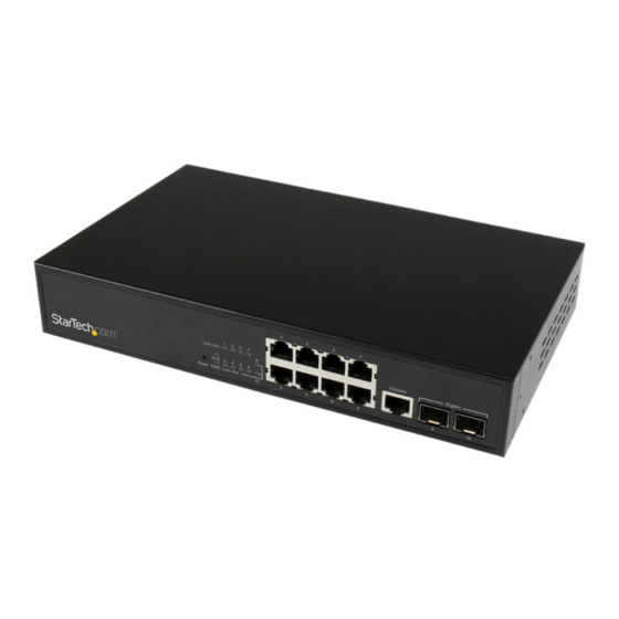
10-Port L2 Managed Gigabit Ethernet
Switch with 2 SFP Slots - Rack Mountable
IES101002SFP
DE: Bedienungsanleitung - de.startech.com
FR: Guide de l'utilisateur - fr.startech.com
ES: Guía del usuario - es.startech.com
IT: Guida per l'uso - it.startech.com
NL: Gebruiksaanwijzing - nl.startech.com
PT: Guia do usuário - pt.startech.com
For the latest information, technical specifications, and support for
this product, please visit www.startech.com/IES101002SFP.
Manual Revision: 08/07/2015
*actual product may vary from photos
Advertisement
Table of Contents

Related Manuals for StarTech.com IES101002SFP


Summary of Contents for StarTech.com IES101002SFP
- Page 1 Switch with 2 SFP Slots - Rack Mountable IES101002SFP *actual product may vary from photos DE: Bedienungsanleitung - de.startech.com FR: Guide de l'utilisateur - fr.startech.com ES: Guía del usuario - es.startech.com IT: Guida per l'uso - it.startech.com NL: Gebruiksaanwijzing - nl.startech.com PT: Guia do usuário - pt.startech.com...
- Page 2 StarTech.com. Where they occur these references are for illustrative purposes only and do not represent an endorsement of a product or service by StarTech.com, or an endorsement of the product(s) to which this manual applies by the third-party company in question. Regardless of any direct acknowledgement elsewhere in the body of this document, StarTech.com hereby...
-
Page 3: Table Of Contents
Table of Contents Product diagram ..................1 Front view ..............................1 Rear view ..............................1 Introduction ....................2 Packaging contents ..........................2 Features ................................ 2 Specifications.............................. 4 Performances .............................. 4 LED indicators ............................. 5 Web management ..................6 Configure the switch for the first time ....................6 Change your password ........................... - Page 4 Set up the Secure Shell management interface ................32 Enable HTTPS ............................. 33 Configure the access management settings ................... 33 Configure the SNMP settings ........................ 34 Change the SNMPv3 community configuration settings ............35 Change the SNMPv3 User settings ..................... 36 Change the SNMPv3 Group settings ....................
- Page 5 Change the CIST ports settings ......................68 Change the MSTI Ports settings ......................70 Change the MVR settings ........................71 Change the IGMP Snooping Configuration settings ..............73 Change the VLAN Configuration settings ..................74 Change the Port Group Filtering settings ..................75 Change the Basic Configuration settings ..................
- Page 6 Change the QoS Control List settings ....................105 Change the Storm Control settings ....................107 Change the Mirror Configuration settings ..................108 Change the UPnP settings ........................108 Change the sFlow settings........................109 Changing the Monitor settings ............112 Change the Information settings ......................112 Change the CPU Load settings ......................
- Page 7 Change the System Status settings ....................139 Change the Port Status settings ......................140 Change the Port Statistics settings ..................... 141 Change the Loop Protection settings ....................141 Change the Bridge Status settings ..................... 142 Change the Port Status settings ......................144 Change the Port Statistics settings .....................
- Page 8 Restore the factory default settings ....................167 Update your firmware ..........................167 Change the Image Select settings ...................... 168 Save the switch configuration to an XML file.................. 168 Restore the switch to a backup configuration ................168 Technical Support ..................169 Warranty Information ................169 Instruction Manual...
-
Page 9: Product Diagram
Product diagram Front view Gigabit Ethernet RJ45 ports LED indicators Reset button Console RJ45 port Gigabit Open SFP slots Rear view DC power Cooling fan Instruction Manual... -
Page 10: Introduction
Introduction This switch is a Web Smart switch equipped with 8 ports 10/100/1000BaseT(X) and 2 ports Gigabit SFP open slots, and provides a broad range of features for Layer2 switching. It was designed for easy installation and high performance in an environment where the traffic is on the network and the number of users increases continuously. - Page 11 Authentication Telnet, Web - user name and password Telnet - Secure Shell (SSH) Simple Network Management Protocol (SNMP) v1/v2c - community strings SNMP version 3 - MD5 or SHA password Port-based 802.1x Port limiting Input rate limiting per port (manual setting or ACL) Port configuration Speed, duplex mode, flow control, maximum transmission unit (MTU), and power saving mode...
-
Page 12: Specifications
Specifications Standard • IEEE 802.3ad link aggregation • IEEE 802.3x flow control • IEEE 802.1x Port-based Network Access Control • IEEE 802.1Q VLAN tagging • IEEE 802.1D Spanning Tree Protocol • IEEE 802.1w Rapid Spanning Tree Protocol • 24 integrated IEEE 802.3ab-compliant 10/100/1000BASE-T Ethernet MIBs •... -
Page 13: Led Indicators
LED indicators The LED indicators present real-time information about systematic operation status. The following table provides descriptions of LED statuses and meanings. Status Description Power System is on System is off Link or activity Blinking Activating link and data Port is disabled or disconnected Instruction Manual... -
Page 14: Web Management
Web management The following section describes the features of the Web Smart switch, including instructions on how to configure each feature using the Web interface. Configure the switch for the first time Note: You can use the LED activity to check the status of the switch while you configure it. -
Page 15: Change Your Password
Change your password After you set up the switch for the first time, before you configure the switch, you should change the password. To change your password, complete the following steps: 1. On your computer, open a Web browser and navigate to 192.168.2.1. 2. - Page 16 When you log in to the Web management UI, the default screen that you see is the Port State Overview screen: Ports 1 to 8 are Gigabit Ethernet ports, and ports 9 and 10 are the SFP slots. When the port image is green, it means that the port is connected.
- Page 17 To access the menu options, on the left side of the main screen of the Web management UI, click Configuration > Power Reduction > <menu option>. Menu option Description Reduce the LED intensity during specified hours, and configure the link change at error settings. EEE (Energy Efficient Turn on and turn off EEE, and configure the EEE urgent Ethernet)
- Page 18 HTTPS Turn on and turn off HTTPS and specify the auto-redirect setting. Access Management Turn on and turn off Access Management, set the IP address range for HTTP and HTTPS, and specify the SNMP and TELNET/SSH access. To access the menu options, on the left side of the main screen of the Web management UI, click Configuration >...
- Page 19 To access the menu options, on the left side of the main screen of the Web management UI, click Configuration > Security > Network > <menu option>. Menu option Description Limit Control Limit the numer of users on a specific port. Configure the Network Access Server.
- Page 20 To access the menu options, on the left side of the main screen of the Web management UI, click Configuration > Security > Network > ARP Inspection > <menu option>. Menu option Description Configuration Turn on and turn off the Global ARP inspection. Static Table Manually insert the ARP Inspection table.
- Page 21 Ports Specify the default PVID and VLAN attributes. CIST Ports Configure the interface settings for STA. MSTI Ports Configure the interface settings for an MST instance. To access the menu options, on the left side of the main screen of the Web management UI, click Configuration >...
- Page 22 To access the menu options, on the left side of the main screen of the Web management UI, click Configuration > VLANs > <menu option>. Menu option Description VLAN Memberships Specify the VLAN groups. Ports Configure the VLAN setting for each port. To access the menu options, on the left side of the main screen of the Web management UI, click Configuration >...
- Page 23 To access the menu options, on the left side of the main screen of the Web management UI, click Configuration > Voice VCL > <menu option>. Menu option Description Configuration Configure the global settings, allow or block Voice VLAN by port setting.
- Page 24 About the menu options in the Monitor drop-down list To access the menu options, on the left side of the main screen of the Web management UI, click Monitor > System > <menu option>. Menu option Description Information View the system contact, name, location, system time, firmware version, and the MAC address for the switch.
- Page 25 To access the menu options, on the left side of the main screen of the Web management UI, click Monitor > Security > Network > Port Security > <menu option>. Menu option Description Switch View the module legend and the status of each port, including the MAC address learning and the maximum allowed MAC count.
- Page 26 To access the menu options, on the left side of the main screen of the Web management UI, click Monitor > Security > AAA > <menu option>. Menu option Description RADIUS Overview View the status of the associated authentication RADIUS servers.
- Page 27 To access the menu options, on the left side of the main screen of the Web management UI, click Monitor > <menu option>. Menu option Description Loop Protection View the loop status for each port. MAC Table View the Dynamic and Static MAC address table. sFlow View the receiver and per-port sFlow statistics.
- Page 28 To access the menu options, on the left side of the main screen of the Web management UI, click Monitor > IPMC > IGMP Snooping > <menu option>. Menu option Description Status View the statistics related to IGMP packets passed upstream to the IGMP Querier or downstream to multicast clients.
- Page 29 To access the menu options, on the left side of the main screen of the Web management UI, click Monitor > VLANs > <menu option>. Menu option Description VLAN Membership View the port members for a specific VLAN ID. VLAN Port View the VLAN Port Status for a Static user.
- Page 30 About the menu options in the Maintenance drop-down list To access the menu options, on the left side of the main screen of the Web management UI, click Maintenance > Software > <menu option>. Menu option Description Upload Use the Web UI to update the firmware for the switch. Image Select Select a recovery firmware to use to start the switch.
-
Page 31: Changing The Configuration Settings
Changing the Configuration settings Change the System Information settings 1. On the main screen of the Web management UI, click Configuration > System > Information. 2. Do any of the following: • To specify an administrator for the switch, in the System Contact field, enter a name (maximum length is 255 characters). -
Page 32: Change The System Ipv6 Settings
To configure the static IP address and enable the DHCP client, do the following: 1. On the main screen of the Web management UI, click Configuration > System > IP. 2. Do one of the following: • To enable the DHCP client, select the DHCP check box. •... -
Page 33: Change The Ntp Configuration Settings
4. If necessary, complete the Router field. 5. To renew the IPv6 Address, click Renew. 6. To apply the changes that you made, click Save. To restore the previous settings, click Restore. Change the NTP Configuration settings The following table describes the NTP Configuration settings that you can change: Option Description Mode... - Page 34 Date Specify the day to start and end daylight saving time. Year Specify the year to start and end daylight saving time. Hours Specify the hour to start and end daylight saving time. Minutes Specify the minute to start and end daylight saving time. Offset Specify the number of minutes to add during daylight saving time.
-
Page 35: Change The Log Settings
Change the Log settings The following table describes the Log settings that you can change: Option Description Server Mode Enable or disable remote system logging. Server Address Specify the IP address of the server used for remote system logging. Syslog Level Select one of the following logging event levels: Info, Warning, or Error. -
Page 36: Change The Eee Settings
On time at link Set the duration of time that the LED operates at full power change when a link change occurs. On at errors Set the LED to operate at full power when an error occurs. 1. On the main screen of the Web management UI, click Configuration > Power Reduction >... -
Page 37: Change The Port Settings
Change the Port settings On the Port Configuration screen, you can specify the parameters for each port, including enabling and disabling ports, setting port speeds such as auto, half-duplex, full-duplex, and more. You can also set the frame size, specify the collision policy and power control. -
Page 38: Change The User Settings
3. To enable flow control, select the Configured check box. 4. To specify the maximum frame size allowance to transfer for each port, in the Maximum Frame Size field, enter a numeric value. 5. To change the settings for the excessive collision mode, in the Excessive Collision Mode drop-down list, click an option. -
Page 39: Change The Privilege Levels Settings
3. In the Privilege Level drop-down list, click a level option. 4. To save your changes, click Save. 5. To cancel your changes, click Cancel. To restore the previous settings, click Reset. Change the Privilege Levels settings On the Privilege Levels screen, you can set the privilege level required to read or configure a software module or system setting. -
Page 40: Set Up The Secure Shell Management Interface
Option Description Client Specify the authentication method for the administrator. Authentication Method Select 1 of 4 authentication methods. Fallback Set the switch to check by local password if fallback is checked when radius server authentication fails. 1. On the main screen of the Web management UI, click Configuration > Security > Switch >... -
Page 41: Enable Https
Enable HTTPS On the HTTPS Configuration screen, you can enable or disable HTTPS and Automatic Redirect mode. When Automatic Redirect mode is enabled, the Web browser is automatically redirected to an HTTPS connection when both HTTPS and Automatic Redirect modes are enabled. 1. -
Page 42: Configure The Snmp Settings
Configure the SNMP settings On the SNMP System Configuration screen, you can configure the SNMP settings, including community name, trap host, public traps, and so on. See the table below for more information about the settings that you can change. Option Description Mode... -
Page 43: Change The Snmpv3 Community Configuration Settings
Trap Security Engine ID View the SNMP trap security engine ID (only available for SNMP v3). Trap Security Name View the trap security name (only available for SNMP v3). 1. On the main screen of the Web management UI, click Configuration > Security > Switch >... -
Page 44: Change The Snmpv3 User Settings
Source IP Specify the IP address of the SNMP client. Source Mask Specify the subnet mask of the SNMP client. 1. On the main screen of the Web management UI, click Configuration > Security > Switch > SNMP > Communities. 2. -
Page 45: Change The Snmpv3 Group Settings
Privacy Protocol Set the encryption algorithm (none or 56-bit DES). Privacy Password Set a privacy passphrase between 8 and 40 characters long). 1. On the main screen of the Web management UI, click Configuration > Security > Switch > SNMP > Users. 2. -
Page 46: Change The Snmpv3 View Settings
Change the SNMPv3 View settings On the SNMPv3 View Configuration screen, you can define the restricts access policy for a specific MIB tree. The default_view includes access ability for the whole MIB tree. See the table below for more information about the settings that you can change. Option Description View Name... -
Page 47: Change The Rmon Statistics Settings
Security Level Set 1 of 3 security levels: • NoAuth, NoPriv (no authentication and encryption applied during the communication). • Auth, NoPriv (the communication has authentication applied to it, but not encryption). • Auth, Priv (both authentication and encryption are applied during the communication). -
Page 48: Change The Rmon History Settings
1. On the main screen of the Web management UI, click Configuration > Security > Switch > RMON > Statistics. 2. To create a new MIBs, click Add New Entry. 3. In the ID field, enter an ID number. 4. In the Data Source field, enter a port number. 5. -
Page 49: Change The Rmon Alarm Settings
Change the RMON Alarm settings On the RMON Alarm Configuration screen, you can set the threshold to use for sending the SNMP trap. See the table below for more information about the settings that you can change. Option Description Configure index of the entry. The index range is between 1 and 65535. Interval Set the interval in seconds for sampling and comparing the rising and falling threshold. - Page 50 Delete Delete the RMON Alarm configuration entry. Sample Select the method of sampling the selected variable and calculating Type the value to be compared against the threshold. Possible sample types include Absolute (directly get the sample) and Delta (calculate the difference between samples).
-
Page 51: Change The Rmon Event Settings
Change the RMON Event settings On the RMON Event Configuration screen, you can set up a trigger when an alarm trigger occurs. See the table below for more information about the settings that you can change. Menu option Description Delete Delete the Event configuration entry. -
Page 52: Change The Port Security Limit Control Settings
Change the Port Security Limit Control settings On the Port Security Limit Control Configuration screen, you can limit the number of users who are accessing a specific port. Users are identified by a MAC address or VLAN ID. If Limit Control is enabled on a port, the limit specifies the maximum number of users that can be on a port, and if the number is exceeded, action is taken. - Page 53 Action There are three ways to reopen a port: 1. Turn on the switch. 2. Disable and enable the Limit Control on the port or the switch again. 3. Click the Re-open button. • Trap&Shutdown (if Limit+ 1 MAC address is seen on the port, both the Trap and the Shutdown actions described above will be taken).
-
Page 54: Change The Network Access Settings
Change the Network Access settings On the Network Access Server Configuration screen, you can configure network authentication settings. See the table below for more information about the settings that you can change. Menu option Description Mode Indicates if Network Access Server (NAS) is globally enabled or disabled on the switch. - Page 55 Aging Period This setting applies to the following modes: 1) Single 802.1X 2) Multi 802.1X 3) MAC-Based Auth. The Port Security Module scans for activity on the MAC addresses at regular intervals and frees up resources if no activity is seen within a given period of time.
- Page 56 RADIUS-Assigned QoS RADIUS-assigned QoS lets you centrally control the Enable traffic class to which traffic coming from a successfully authenticated client is assigned on the switch. The RADIUS server must be configured to transmit special RADIUS attributes to take advantage of this feature. The RADIUS-Assigned QoS Enabled check box provides a quick way to globally enable/disable RADIUS-server assigned QoS class functionality.
- Page 57 Guest VLAN ID This is the value that a Port VLAN ID is set to if the port is moved into the Guest VLAN. This value can only be changed if the Guest VLAN option is enabled globally. Valid values are in the range of 1 to 255. Allow Guest VLAN if EAPOL The switch remembers if an EAPOL frame has been Seen...
- Page 58 [Single 802.1x] Only one supplicant can be authenticated on the port at any time. If more than one supplicant is connected to a port, the one that comes first when the port’s link comes up will be the first one considered. If the first supplicant fails to authenticate, the second supplicant is then considered.
- Page 59 [Guest VLAN Enabled] This feature can be enabled or disabled for a given port. Port State The current state of the port: [Globally Disabled] 802.1X and MAC-based authentication are globally disabled. [Link Down] 802.1X and MAC-based authentication is enabled, but no link on the given port.
-
Page 60: Change The Ports Settings
Change the Ports settings On the ACL Ports Configuration screen, you can specify the assigned port reactions when specific frames are matched. These behaviors include Port Redirect, Mirror, Logging, and Shutdown. To access the ACL Ports Configuration screen, click Configuration > Security > Network >... -
Page 61: Change The Rate Limiters Settings
1. On the main screen of the Web management UI, click Configuration > Security > Network > ACL > Ports. 2. Assign a Policy ID to a given port and set the related ACE parameters. Options include Action, Rate Limiter ID, Port Redirect, Mirror, Logging, Shutdown, and State. -
Page 62: Change The Access Control List Settings
Change the Access Control List settings You can use the Access Control List screen to define the ACE settings on the switch. Each row describes the ACE that is defined. You can define filtering rules for an ACL policy, for a specific port, or for all ports. See the table below for more information about the settings that you can change. - Page 63 Port Redirect Indicates the port redirect operation of the ACE. Frames matching the ACE are redirected to the port number. The allowed values are Disabled or a specific port number. When Disabled is displayed, the port redirect operation is disabled Mirror Specifiy the mirror operation of this port.
-
Page 64: Change The Snooping Configuration Settings
Change the Snooping Configuration settings You can use the DHCP Snooping Configuration screen to filter IP traffic on insecure ports for which the source address can’t be identified using DHCP snooping. To access the DHCP Snooping Configuration screen, click Configuration > Security >... -
Page 65: Change The Relay Settings
Change the Relay settings Using the DHCP Relay Configuration screen, you can configure DHCP relay service for attached host devices. If a subnet doesn’t include a DHCP server, you can relay DHCP client requests to a DHCP server on another subnet. To access the DHCP Relay Configuration screen, click Configuration >... - Page 66 Relay Indicates the DHCP relay information policy option. When DHCP Information relay information mode operation is enabled, if an agent receives Policy a DHCP message that already contains relay agent information, it will enforce the policy. The Replace option is invalid when relay information mode is disabled.
-
Page 67: Change The Ip Source Guard Settings
Change the IP Source Guard settings You can use the IP Source Guard table (manually insert MAC Address table) or DHCP Snooping table (dynamic MAC address table) to filter IP traffic on switch ports. To access the IP Source Guard screen, click Configuration > Security > Network > IP Source Guard. -
Page 68: Change The Static Table Settings
Change the Static Table settings You can create a Static Port-VLAN-IP Address-MAC address mapping table for IP Source Guard usage. The following table describes the options for configuring the mapping table: Menu option Description Delete Select to delete the entry. It will be deleted during the next save. Port The logical port of the settings. -
Page 69: Change The Static Arp Inspections Table Settings
3. Select Enabled or Disabled for each port. 4. To save your settings, click Save. To restore the previous settings, click Reset. Change the Static ARP Inspections Table settings Use the Static ARP Inspection table to create a database for validation. The switch first compares ARP packets to any entries specified in the static ARP table. -
Page 70: Change The Static Settings
Menu option Description Common Server Configuration Timeout The maximum waiting time to wait for a reply from server (range is 3 to 3600 seconds). Dead time The time after which the switch considers an authentication server to be dead if it does not reply (range is 0 to 3600 seconds). RADIUS Authentication Server Configuration Enable Enable the RADIUS Authentication Server by selecting this check... -
Page 71: Change The Lacp Settings
IP address The IP Address can be used to calculate the destination port for the frame. Select to enable the use of the IP Address, or unselect to disable. By default, IP Address is enabled. TCP/IP port The TCP/IP port number can be used to calculate the destination number port for the frame. - Page 72 LACP enabled Controls whether LACP is enabled on this switch port. LACP will form an aggregation when two or more ports are connected to the same partner. LACP can have up to 12 LLAGs per switch and GLAGs per stack.. The Key value incurred by the port.(Range is 1 to 65535.) The “Auto”...
-
Page 73: Change The Loop Protection Settings
Change the Loop Protection settings You can access the Loop Protection screen by clicking Configuration > Loop Protection. Menu option Description General Settings Enable loop Controls whether loop protection is enabled. protection Transmission The interval between each loop protection PDU sent on each time port. -
Page 74: Change The Spanning Tree Settings
Change the Spanning Tree settings The Spanning Tree algorithm enables the switch to cooperate with other bridging devices by detecting and disabling network loops and providing backup links between switches, bridges, and routers. You can access the Spanning Tree screen by clicking Configuration > Spanning Tree >... -
Page 75: Change The Msti Mapping Settings
1. On the main screen of the Web management UI, click Configuration > Spanning Tree > Bridge Settings. 2. Configure the required attributes. 3. To save your settings, click Save. To restore the previous settings, click Reset. Change the MSTI Mapping settings Use the MSTI Mapping screen to inspect the current STP MSTI bridge instance priorities configuration and change them if necessary. -
Page 76: Change The Msti Priorities Settings
Change the MSTI Priorities settings Use the MSTI Priorities screen to configure the bridge priority for the CIST and any configured MSTI. RSTP recognizes each MST Instance as a single bridge node. You can access the screen by clicking Configuration > Spanning Tree > MSTI Priorities. - Page 77 Path Cost Control the Path Cost incurred by this port. The “Auto” setting will set the path cost as appropriate by physical link speed, using the 802.1D recommended values. Using “specific” settings, a user-defined value can be entered. The path cost is used when establishing the active topology of the network.
-
Page 78: Change The Msti Ports Settings
3. To save your settings, click Save. To restore the previous settings, click Reset. Change the MSTI Ports settings The MSTI ports configuration screen allows the user to inspect the current STP MSTI port configurations and possibly change them as well. An MSTI port is a virtual port, which is instantiated separately for each active CIST(physical) port for each MSTI instance configured on and applicable to the port.The MSTI instance must be selected before displaying actual MSTI port configuration options. -
Page 79: Change The Mvr Settings
Change the MVR settings You can enable multicast traffic forwarding on the multicast VLANs by using the MVR configuration screen. In a multicast television application, a PC, a network television, or set-top box can receive the multicast stream. Multiple set-top boxes or PCs can be connected to one subscriber port, which is a switch port configured as an MVR receiver port. - Page 80 LLQI Defines the maximum time to wait for IGMP/MLD report memberships on a receiver port before removing the port from multicast group membership. The value is in units of tenths of a seconds. The range is from 0 to 31744. The default LLQI is 5 tenths or one-half second.
-
Page 81: Change The Igmp Snooping Configuration Settings
Change the IGMP Snooping Configuration settings Multicasting is used to support real-time applications such as video-conferencing or streaming audio. A multicast server doesn’t have to establish a separate connection to each client; it only broadcasts its service to the network. Using this approach will significantly increase broadcast traffic on the network. -
Page 82: Change The Vlan Configuration Settings
Throttling Set this to Enable to limit the number of multicast groups to which a switch port can belong. 1. On the main screen of the Web management UI, click Configuration > IPMC > IGMP Snooping > Basic Configuration. 2. Specify the required IGMP Snooping settings. 3. -
Page 83: Change The Port Group Filtering Settings
Query Response Interval. The maximum Response Delay used to calculate the Maximum Response Code inserted into the periodic General Queries. The allowed range is 0 to 31744 in tenths of seconds, and the default query response interval is 100 in tenths of seconds(10 seconds). -
Page 84: Change The Basic Configuration Settings
1. On the main screen of the Web management UI, click Configuration > IPMC > IGMP Snooping > Port Group Filtering. 2. Click Add New Filtering Group. 3. To save your settings, click Save. To restore the previous settings, click Reset. Change the Basic Configuration settings Multicast Listener Discovery snooping is available on IPv6 network and performs a similar function to IGMP for IPv4. -
Page 85: Change The Vlan Configuration Settings
2. Compile the MLD-related parameters. 3. To save your settings, click Save. To restore the previous settings, click Reset. Change the VLAN Configuration settings Use the MLD Snooping VLAN Configuration screen to configure MLD snooping and query for a VLAN interface. You can access the screen by clicking Configuration >... -
Page 86: Change The Mld Configuration Settings
LLQI Last listener Query Interval. The Last Listener Query Interval is the Maximum Response Delay used to calculate the Maximum Response Code inserted into Multicast Address Specific Queries sent in response to Version 1 Multicast Listener Done messages. It is also the Maximum Response Delay used to calculate the Maximum Response Code inserted into Multicast Address and Source Specific query message. -
Page 87: Change The Lldp Settings
1. On the main screen of the Web management UI, click Configuration > IPMC > MLD Snooping > Port Group Filtering. 2. To add a new entry, click Add New Filtering Group. 3. To save your settings, click Save. To restore the previous settings, click Reset. Change the LLDP settings Use the LLDP Configuration screen to set the timing parameters for LLDP advertisements and the device information which is advertised. - Page 88 [Rx only] The switch will not send out LLDP information, but LLDP information from neighbour units is analyzed. [Tx only] The switch will drop LLDP information received from neighbours, but will send out LLDP information. [Disabled] The switch will not send out LLDP information, and will drop LLDP information received from neighbours.
-
Page 89: Change The Lldp-Med Settings
Sys Name Optional TLV: When selected, the “system name” is included in LLDP information transmitted. Sys Capa Optional TLV: When selected, the “system capability” is included in LLDP information transmitted. Mgmt Addr Optional TLV: When selected, the “management address” is included in LLDP information transmitted. - Page 90 Fast start repeat With this in mind, LLDP-MED defines an LLDP-MED Fast Start count interaction between the protocol and the application layers on top of the protocol, in order to achieve these related properties. Initially, a Network Connectivity Device will only transmit LLDP TLVs in an LLDPDU.
- Page 91 Altitude Altitude SHOULD be normalized to within -32767 to 32767 with a maximum of 4 digits.It is possible to select between two altitude types (floors or meters). Meters: Representing meters of Altitude defined by the vertical datum specified. Floors: Representing altitude in a form more relevant in buildings which have different floor-to-floor dimensions.
- Page 92 Leading street Leading street direction – Example : N direction Trailing street suffix Trailing street suffix – Example: SW Street suffix Street suffix – Example: Ave, Platz. House no. House number – Example : 21 House no. suffix House number suffix. Examples: A, 1/2 Landmark Landmark or vanity address –...
- Page 93 Policies Network Policy Discovery enables the efficient discovery and diagnosis of mismatch issues with the VLAN configuration, along with the associated Layer 2 and Layer 3 attributes. Policies are only intended for use with applications that have specific “real-time” network policy requirements, such as interactive voice and/or video service.
- Page 94 Application Type Intended use of the application types: 1. Voice For use by dedicated IP Telephony handsets and other similar appliances supporting interactive voice services. These devices are typically deployed on a separate VLAN for ease of deployment and enhanced security by isolation from data applications.
- Page 95 8. Video Signalling For use in network topologies that require a separate policy (conditional) for the video signalling than for the video media. This application type should not be advertised if all of the same network policies apply as those advertised in the Video Conferencing application policy.
-
Page 96: Change The Mac Table Settings
Change the MAC Table settings Use the MAC Address Table Configuration screen to configure dynamic address learning or to assign static addresses to specific ports. You can access the screen by clicking Configuration > MAC Table. Menu option Description Aging Configuration Disable Automatic Do not automatically remove default dynamic entries from Aging... -
Page 97: Change The Vlan Memberships Settings
Change the VLAN Memberships settings VLAN provides greater network performance by reducing broadcast traffic. It also provides a high level of network security because traffic must pass through a configured Layer 3 link to reach a different VLAN. You can monitor and modify the VLAN Membership Configuration for the switch here. Up to 4096 VLANs are supported. - Page 98 Menu option Description EtherType for Specify the EtherType used for Custom S-ports. This is a global Custom S-ports setting for all the Custom S-ports. Port Specify the logical port number of this row. Port Type Specify the port type: Unaware, Customer port (C-port), Service Port (S-port), Or Custom Service port (S-custom-port).
-
Page 99: Change Pvlan Membership Settings
1. On the main screen of the Web management UI, click Configuration > VLANs > Ports. 2. Configure the required settings for each interface. 3. To refresh the display table starting from the first entry of the VLAN table, click Refresh. -
Page 100: Change The Port Isolation Settings
Change the Port Isolation settings Use the Port Isolation Configuration screen to prevent communications between customer ports within the same private VLAN. You can access the screen by clicking Configuration > Private VLANs > Port Isolation. Menu option Description Port Members Enable port isolation for ports. -
Page 101: Change The Protocol To Group Settings
1. On the main screen of the Web management UI, click Configuration > VCL > MAC- based VLAN. 2. To add a new entry, click Add New Entry. 3. Insert the MAC Address and VLAN ID and select the applied ports. 4. -
Page 102: Change The Group To Vlan Settings
[For SNAP] a. OUI: OUI (Organizationally Unique Identifier) is a value in the format xx-xx-xx where each pair (xx) in the string is a hexadecimal value, ranging from 0x00-0xff. b. PID: If the OUI is the hexadecimal 000000, the protocol ID is the Ethernet type (EtherType) field value for the protocol running on top of SNAP. -
Page 103: Change The Ip Subnet-Based Vlan Settings
Group Name A valid Group Name is a string of up to 16 characters, which consists of a combination of letters (a-z or A-Z) and integers (0-9). No special character is allowed. Whichever Group Name you map to a VLAN must be present in the Protocol to Group mapping table and must not be already used by any other existing entry on this page. -
Page 104: Change The Voice Vlan Configuration Settings
VLAN ID Indicates the VLAN ID. VLAN ID can be changed for the existing entries. Port Members A row of check boxes for each port is displayed for each IP subnet-based VLAN entry. To include a port in an IP subnet-based VLAN, check the box. -
Page 105: Change The Oui Settings
Aging Time Indicates the Voice VLAN secure learning aging time. The allowed range is 10 to 10000000 seconds. It is used when security mode or auto detect mode is enabled. In other cases, it will be based on hardware aging time. Traffic Class Indicates the Voice VLAN traffic class. -
Page 106: Change The Port Classification Settings
Menu option Description Delete Select to delete the entry. It will be deleted during the next save. Telephony OUI A telephony OUI address is a globally unique identifier assigned to a vendor by IEEE. It must be 6 characters long and the input format is “xx-xx-xx”... -
Page 107: Change The Port Policing Settings
Controls the default Priority Code Point (PCP). All frames are classified to a PCP value. If the port is VLAN aware and the frame is tagged, then the frame is classified to the PCP value in the tag. Otherwise the frame is classified to the default PCP value. -
Page 108: Change The Port Scheduler Settings
Enabled Controls whether the policer is enabled on this switch port. Rate Controls the rate for the policer. The default value is 500. This value is restricted to 100-1000000 when the “Unit” is “kbps” or “fps”, and it is restricted to 1-3300 when the “Unit” is “Mbps” or “kfps”. -
Page 109: Change The Port Shaping Settings
Change the Port Shaping settings Use the QoS Egress Port shapers to show an overview of the QoS Egress Port Shapers. Include rate of each queue and port. Click the port number to configure. You can access the screen by clicking Configuration > QoS > Port Shaping. Menu option Description Port... -
Page 110: Change The Port Dscp Settings
1. On the main screen of the Web management UI, click Configuration > QoS > Port Tag Remarking. 2. On the Overview screen, click the port number for the Tag Remarking settings for each specific port. 3. To apply your changes, click Save. To restore the previous settings, click Reset. -
Page 111: Change The Dscp-Based Qos Settings
Egress Port Egress Rewriting can be one of the following: Disable: No egress rewrite. Enable: Rewrite enabled without remapping. Remap DP Unaware: DSCP from the analyzer is remapped and the frame is remarked with the remapped DSCP value. The remapping DSCP value is always taken from the “DSCP Translation->Egress Remap DP0”... -
Page 112: Change The Dscp Translation Settings
1. On the main screen of the Web management UI, click Configuration > QoS > DSCP- Based QoS. 2. Specify whether the DSCP value is trusted or not and set the corresponding QoS value and DP level for ingress frames. 3. -
Page 113: Change The Dscp Classification Settings
Change the DSCP Classification settings Use the DSCP Classification screen to map DSCP values to a QoS class and drop precedence level. You can access the screen by clicking Configuration > QoS > DSCP Classification. Menu option Description QoS Class Actual QoS class. - Page 114 Frame Type Indicates the type of frame to look for on incoming frames. Possible frame types are: Any: The QCE will match all frame type. Ethernet: Only Ethernet frames (with Ether Type 0x600- 0xFFFF) are allowed. LLC: Only (LLC) frames are allowed. SNAP: Only (SNAP) frames are allowed.
-
Page 115: Change The Storm Control Settings
1. On the main screen of the Web management UI, click Configuration > QoS > QoS Control List. 2. Click the + button to add a new QoS control list. 3. Scroll all of the parameters and evoke the port member to join the QCE rules 4. -
Page 116: Change The Mirror Configuration Settings
Change the Mirror Configuration settings Use the Mirror Configuration screen to mirror traffic from any source port to a target port. You can access the screen by clicking Configuration > Mirroring. Menu option Description Port The logical port for the settings is contained in the same row. Mode Select mirror mode. -
Page 117: Change The Sflow Settings
Menu option Description Mode Indicates the UPnP operation mode. Possible modes are: Enabled: Enable UPnP mode operation Disabled: Disable UPnP mode operation When the mode is enabled, two ACEs are added automatically to trap UPNP related packets to CPU. The ACEs are automatically removed when the mode is disabled. - Page 118 Menu option Description Receiver Configuration Owner sFlow can be configured in two ways: through local management using the web or CLI interface or through SNMP. This read-only field shows the owner of the current sFlow configuration and assumes values as follows: If sFlow is currently unconfigured/unclaimed, Owner contains <none>.
- Page 119 Flow Sampler The statistical sampling rate for packet sampling. Set to N Sampling to sample on average 1/Nth of the packets transmitted/ received on the port. Not all sampling rates are achievable. If an unsupported sampling rate is requested, the switch will automatically adjust it to the closest achievable.
-
Page 120: Changing The Monitor Settings
Changing the Monitor settings This section describes how to monitor all of the basic functions, including configuration, the system log, traffic views, and the switch or port states. Change the Information settings Use the System Information screen to verify the firmware and hardware versions. It also displays the system contact, device name, location, and system uptime. -
Page 121: Change The Cpu Load Settings
Change the CPU Load settings This screen displays the CPU load, using an SVG graph. The load is measured as average over the last 100 ms, 1 second, and 10 seconds intervals. The last 120 samples are graphed and the last numbers are displayed as text as well. In order to display the SVG graph, your browser must support SVG format. -
Page 122: Change The Detailed Log Settings
Buttons (cont’d) >>: Updates the system log entries, starting from the last entry currently displayed. >> : Updates the system log entries, ending at the last available entry ID. 1. On the main screen of the Web management UI, click Monitor > System > Log. 2. -
Page 123: Change The Detailed Log Settings
Change the Detailed Log settings The Port State screen provides an overview of the current state of all ports. You can click a port’s icon to get detailed statistics for the port. You can access the screen by clicking Monitor > Ports > State. Menu option Description Port State... -
Page 124: Change The Qos Statistics Settings
Drops The number of frames discarded due to ingress or egress congestion. Filtered The number of received frames filtered by the forwarding process. Buttons Auto-refresh: Select this check box to enable an automatic refresh of the page at regular intervals. Refresh: Updates the system log entries, starting from the current entry ID. -
Page 125: Change The Qcl Status Settings
3. To automatically update the switch’s port state, select the Auto-refresh check box. Change the QCL Status settings Use the QoS Control List Status to show the QCE configured for different users or software modules, and see whether there is a conflict. You can access the screen by clicking Monitor >... -
Page 126: Change The Detailed Statistics Settings
Conflict Displays the conflict status of QCL entries, as hardware resources are shared by multiple applications. Resources required to add a QCE might not be available. In this case it shows the conflict status as Yes; otherwise, it is always No. You can resolve a conflict by pressing the Resolve Conflict button. - Page 127 Rx and Tx Broadcast The number of received and transmitted (good and bad) broadcast packets. Rx and Tx Pause A count of the MAC Control frames received or transmitted on this port that have an opcode indicating a PAUSE operation. Receive and Transmit The number of received and transmitted (good and bad) Size Counters...
-
Page 128: Change The Acl Status Settings
Buttons Auto-refresh: Select this check box to enable an automatic refresh of the page at regular intervals. Refresh: Updates the system log entries, starting from the current entry ID. Resolve Conflict: Flushes all of the system log entries. 1. On the main screen of the Web management UI, click Monitor > Ports > Detailed Statistics. -
Page 129: Change The Switch Settings
Change the Switch settings This screen shows the Port Security status. Port Security is a module with no direct configuration. Configuration comes indirectly from the user modules. When a user module has enabled port security on a port, the port is set up for software-based learning. -
Page 130: Change The Port Settings
State (cont’d) Limit Reached: The Port Security service is enabled by at least the Limit Control user module. Also, that module has indicated that the limit is reached and no more MAC addresses should be taken in. Shutdown: The Port Security service is enabled by at least the Limit Control user module, and that module has indicated that the limit is exceed. -
Page 131: Change The Switch Settings
Time of Addition Shows the date and time when this MAC address was first seen on the port. Age/Hold If at least one user module has decided to block this MAC address, it will stay in the blocked state until the hold time (measured in seconds) expires. -
Page 132: Change The Nas Statistics Port Settings
Last ID Specifies the user name (supplicant identity) carried in the most recently received Response Identity EAPOL frame for EAPOL-based authentication. Also specifies the source MAC address from the most recently received frame from a new client for MAC-based authentication. QoS class Qos Class assigned to the port by the RADIUS server if enabled. - Page 133 Port Vlan ID The VLAN ID that NAS has put the port in. If the Port VLAN ID is not overridden by NAS, then the field is blank. If the VLAN ID is assigned by the RADIUS server, “(RADIUS-assigned)” is appended to the VLAN ID.
- Page 134 Backend Server The backend (RADIUS) frame counters pictured below are Counters available for the following administrative states: • Port-based 802.1X • Single 802.1X • Multi 802.1X • MAC-based Auth. Last Supplicant/ Information about the last supplicant/client that attempted Client Info to authenticate is pictured below.
- Page 135 Selected Counters The Selected Counters table is visible when the port is in one of the following adminstrative states: • Multi 802.1X • MAC-based Auth. The table is identical to and is placed next to the Port Counters table. It won’t display any information if no MAC address is currently selected.
-
Page 136: Change The Acl Status Settings
1. On the main screen of the Web management UI, click Monitor > Security > Network > NAS > Switch to display information about Port status for authentication services. 2. To periodically refresh the page information, click Auto-refresh. Change the ACL Status settings Each row describes the defined ACE (Access Control Entry). - Page 137 Action Indicates the forwarding action of the ACE. Permit: Frames matching the ACE may be forwarded and learned. Deny: Frames matching the ACE are dropped. Rate Limiter Indicates the rate limiter number of the ACE. The allowed range is 1 to 16. When a Disabled message is displayed, the rate limiter operation is disabled.
-
Page 138: Change The Snooping Statistics Settings
Change the Snooping Statistics settings Use the DHCP Snooping Port Statistics page to show statistics for various types of DHCP protocol packets. You can access the screen by clicking Monitor > Security > Network > DHCP > Snooping Statistics. Menu option Description Rx and Tx Discover Indicates the number of discover (option 53 with value 1) -
Page 139: Change The Relay Statistics Settings
Change the Relay Statistics settings Use the DHCP Relay Statistics screen to show statistics for the DHCP Relay service supported by this switch and DHCP Relay clients. You can access the screen by clicking Monitor > Security > Network > DHCP > Relay Statistics. -
Page 140: Change The Arp Inspection Settings
Keep Agent Option Indicates the number of packets whose relay agent information was retained. Drop Agent Option Indicates the number of packets that were dropped which were received with relay agent information. 1. On the main screen of the Web management UI, click Monitor > Security > Network >... -
Page 141: Change The Ip Source Guard Settings
Change the IP Source Guard settings Entries in the Dynamic IP Source Guard Table are shown on this page. The Dynamic IP Source Guard Table is first sorted by port, then by VLAN ID, then by IP Address, and followed by MAC Address. You can access the screen by clicking Monitor >... -
Page 142: Change The Radius Details Settings
Status Indicates the current status of the server. This field takes one of the following values: Disabled: The server is disabled. Not Ready: The server is enabled, but IP communication is not yet up and running. Ready: The server is enabled, IP communication is up and running, and the RADIUS module is ready to accept access attempts. -
Page 143: Change The Rmon Statistics Settings
Other Info. IP Address: Shows the IP Address of the RADIUS server State: Shows the state of the RADIUS server Round-Trip Time: Shows the handshake time between the RADIUS server and clients Buttons Auto-refresh: Select the Auto-refresh check box to automatically refresh the page at regular intervals. - Page 144 Under-size Indicates the total number of packets received that were less than 64 octets. Over-size Indicates the total number of packets received that were longer than 1518 octets. Frag. Indicates the number of frames whose size is less than 64 octets received with an invalid CRC.
-
Page 145: Change The Rmon History Settings
Change the RMON History settings This screen provides an overview of RMON History entries. You can access the screen by clicking Monitor > Security > Switch > RMON > History. Menu option Description History Index Indicates the index of the history control entry. Sample Index Indicates the index of the data entry associated with the control entry. -
Page 146: Change The Alarm Settings
Jabb. Indicates the number of frames which size is larger than 64 octets received with an invalid CRC. Coll. Indicates the best estimate of the total number of collisions on this Ethernet segment. Utilization Indicates the best estimate of the mean physical layer network utilization on this interface during this sampling interval in hundredths of a percent. -
Page 147: Change The System Status Settings
1. On the main screen of the Web management UI, click Monitor > Security > Switch > RMON > Alarm. 2. To automatically update the page information, select the Auto-refresh check box. Change the System Status settings Use the LACP System Status screen to display an overview of LACP groups. You can access the screen by clicking Monitor >... -
Page 148: Change The Port Status Settings
Change the Port Status settings Use the LACP Port Status screen to display information on the LACP groups active on each port. You can access the screen by clicking Monitor > LACP > Port Status. Menu option Description Indicates the switch port number. Yes indicates that LACP is Port LACP enabled and the port link is up. -
Page 149: Change The Port Statistics Settings
Change the Port Statistics settings Use the LACP Port Statistics screen to display statistics on LACP control packets across each port. You can access the screen by clicking Monitor > LACP > Port Statistics. Menu option Description Port Indicates the switch port number. LACP Received Indicates how many LACP frames have been received at each port. -
Page 150: Change The Bridge Status Settings
Status Indicates the current loop protection status of the port. Loop Indicates whether a loop is currently detected on the port. Time of Last Loop Indicates the time of the last loop event detected. Buttons Auto-refresh: Select the Auto-refresh check box to automatically refresh the page at regular intervals. - Page 151 Topology Flag Indicates the current state of the topology change flag of this bridge instance. Topology Change Indicates the number of times where the topology change Count flag has been set during a one-second interval. Topology Last Indicates the time that has passed since the topology flag was last set.
-
Page 152: Change The Port Status Settings
Change the Port Status settings Use the STP Port Status screen to display the STP CIST port status for physical ports. You can access the screen by clicking Monitor > Spanning Tree > Port Status. Menu option Description Port Indicates the switch port number of the logical STP port. CIST Role Indicates the current STP port role of the CIST port. -
Page 153: Change The Statistics Settings
Indicates the number of (legacy) Topology Change Notification BPDU’s received/transmitted on the port. Discarded Indicates the number of unknown Spanning Tree BPDU’s Unknown received (and discarded) on the port. Discarded Illegal Indicates the number of illegal Spanning Tree BPDUs received (and discarded) on the port. -
Page 154: Change The Mvr Channel Groups Settings
IGMPv3/MLDv2 Reports Indicates the number of Received IGMPv1 Join and Received MLDv2 Report messages, respectively. IGMPv2/MLDv1 Leaves Indicates the number of Received IGMPv2 Leave and Received MLDv1 Done messages, respectively. 1. To display information for MVR Statistics, on the main screen of the Web management UI, click Monitor >... -
Page 155: Change The Snooping Status Settings
Mode Indicates the filtering mode maintained per (VLAN ID, port number, Group Address) basis. It can be Include or Exclude. Source Address Indicates the IP Address of the source. Currently, the system limits the total number of IP source addresses for filtering to 128. -
Page 156: Change The Groups Information Settings
V3 Reports Indicates the number of Received V3 Reports. Received V2 Leaves Received Indicates the number of Received V2 Leaves. Router Port Indicates which ports act as router ports. A router port is a port on the Ethernet switch that leads towards the Layer 3 multicast device or IGMP querier. -
Page 157: Change The Ipv4 Sfm Information Settings
Buttons Auto-refresh: Select the Auto-refresh check box to automatically refresh the page at regular intervals. Refresh: Updates the system log entries, starting from the current entry ID. << : Updates the table starting with the first entry in the IGMP group table. <<: Updates the table starting with the entry after the last entry current displayed. -
Page 158: Change The Mld Status Settings
1. To display the IGMP SFM information, on the main screen of the Web management UI, click Monitor > IPMC > IGMP Snooping > IPv4 SFM Information. Change the MLD Status settings This screen provides MLD Snooping status. You can access the screen by clicking Monitor > IPMC > MLD > Status. Menu option Description VLAN ID... -
Page 159: Change The Groups Information Settings
Status Indicates whether the specific port is a router port or not. 1. To view the IGMP Snooping Status, on the main screen of the Web management UI, click Monitor > System > Information. Change the Groups Information settings Use the MLD Snooping Group Information screen to display the port member of each service group. -
Page 160: Change The Neighbours Settings
Indicates the Type: Allow or Deny. Type Hardware Filter/ Indicates whether the data plane destined to the specific Switch group address from the source IPv4 address could be handled by the chip or not. 1. To view the MLD SFM information, on the main screen of the Web management UI, click Monitor >... -
Page 161: Change The Lldp-Med Neighbours Settings
System Capabilities Indicates the System Capabilities describing the neighbour unit’s capabilities. The possible capabilities are: 1. Other 2. Repeater 3. Bridge 4. WLAN Access Point 5. Router 6. Telephone 7. DOCSIS cable device 8. Station only 9. Reserved When a capability is enabled, the capability is followed by a (+). - Page 162 LLDP-MED Network Connectivity Device Definition LLDP-MED Network Connectivity Devices, as defined in TIA-1057, provide access to the IEEE 802 based LAN infrastructure for LLDP-MED Endpoint Devices. An LLDP-MED Network Connectivity Device is a LAN access device based on any of the following technologies: 1.
- Page 163 Discovery services defined in this class include provision of location identifier (including ECS / E911 information), embedded L2 switch support, inventory management. LLDP-MED LLDP-MED Capabilities describes the neighbour unit’s LLDP- Capabilities MED capabilities. The possible capabilities are: 1. LLDP-MED capabilities 2.
- Page 164 7. Streaming Video - for use by broadcast or multicast based video content distribution and other similar applications supporting streaming video services that require specific network policy treatment. Video applications relying on TCP with buffering would not be an intended use of this application type.
-
Page 165: Change The Eee Settings
Auto-negotiation Auto-negotiation status identifies if auto-negotiation is status currently enabled at the link partner. If Auto-negotiation is supported and Auto-negotiation status is disabled, the 802.3 PMD operating mode will be determined by the operational MAU type field value rather than by auto-negotiation. Auto-negotiation Auto-negotiation Capabilities show the link partners MAC/ Capabilities... - Page 166 Echo Tx Tw Indicates the link partner’s Echo Tx Tw value. The respective echo values is defined as the local link partners reflection (echo) of the remote link partners respective values. When a local link partner receives its echoed values from the remote link partner, it can determine whether or not the remote link partner has received, registered, and processed its most recent values.
-
Page 167: Change The Port Statistics Settings
Change the Port Statistics settings This screen provides an overview of all LLDP traffic. Two types of counters are shown. Global counters are counters that refer to the whole switch, while local counters refer to per port counters for the currently selected switch. You can access the screen by clicking Monitor >... -
Page 168: Change The Mac Table Settings
TLVs Discarded Each LLDP frame can contain multiple pieces of information, known as TLVs (TLV is short for “Type Length Value”). If a TLV is malformed, it is counted and discarded. TLVs Unrecognized Indicates the number of well-formed TLVs, but with an unknown type value. - Page 169 Menu option Description VLAN USER VLAN User module uses services of the VLAN management functionality to configure VLAN memberships and VLAN port configurations such as PVID and UVID. Currently we support the following VLAN user types: CLI/Web/SNMP: These are referred to as static. NAS: NAS provides port-based authentication, which involves communications between a Supplicant, Authenticator, and an Authentication Server.
-
Page 170: Change The Vlan Port Settings
Change the VLAN Port settings Use the VLAN Port Status for a specific user’s page to display the status information of all VLAN Ports status. You can access the screen by clicking Monitor > VLANs > VLAN Port. Menu option Description Port Indicates the logical port for the settings contained in the... -
Page 171: Change The Mac-Based Vlan Settings
Buttons Select VLAN users in the drop-down list. Auto-refresh: Select the Auto-refresh check box to automatically refresh the page at regular intervals. Refresh: Updates the system log entries, starting from the current entry ID. 1. To view the VLAN Port information, on the main screen of the Web management UI, click Monitor >... -
Page 172: Change The Sflow Settings
Change the sFlow settings This screen shows receiver and per-port sFlow statistics. You can access the screen by clicking Monitor > sFlow. Menu option Description Owner This field shows the current owner of the sFlow configuration. It assumes one of three values as follows: •... - Page 173 Rx and Tx Flow Indicates the number of flow samples sent to the sFlow Samples receiver originating from this port. Here, flow samples are divided into Rx and Tx flow samples. Rx flow samples contain the number of packets that were sampled upon reception (ingress) on the port.
-
Page 174: Testing The Connectivity Of The Network
Testing the connectivity of the network This section provides information about IPv4 ping to test the connectivity of the network. Change the Ping settings Use the ICMP Ping screen to send ICMP request packets to another connected point to check if it’s connected. You can access the screen by clicking Diagnostics >... -
Page 175: About Device Maintenance
About device maintenance This section describes how to restart the device, reload the device to default factory settings, save or restore the configuration, as well as upgrading and swapping firmware. Restart the device Use the Restart Device screen to restart the switch. 1. -
Page 176: Change The Image Select Settings
Change the Image Select settings Use the Software Image Selection screen to swap the firmware to an alternative image. You can access the screen by clicking Maintenace > Software > Image Select. Menu option Description Image Indicates the flash index name of the firmware image. The name of primary (preferred) image is image, the alternate image is named image.bk. -
Page 177: Technical Support
Limitation of Liability In no event shall the liability of StarTech.com Ltd. and StarTech.com USA LLP (or their officers, directors, employees or agents) for any damages (whether direct or indirect, special, punitive, incidental, consequential, or otherwise), loss of profits, loss of business, or any pecuniary loss, arising out of or related to the use of the product exceed the actual price paid for the product. - Page 178 StarTech.com is an ISO 9001 Registered manufacturer of connectivity and technology parts. StarTech.com was founded in 1985 and has operations in the United States, Canada, the United Kingdom and Taiwan servicing a worldwide market.
Need help?
Do you have a question about the IES101002SFP and is the answer not in the manual?
Questions and answers