Table of Contents
Advertisement
Quick Links
8-Port Gigabit Ethernet Switch
- Managed
IES81GW
FR: Guide de l'utilisateur - fr.startech.com
DE: Bedienungsanleitung - de.startech.com
ES: Guía del usuario - es.startech.com
NL: Gebruiksaanwijzing - nl.startech.com
PT: Guia do usuário - pt.startech.com
IT: Guida per l'uso - it.startech.com
For the latest information, technical specifications, and support for
this product, please visit www.StarTech.com/IES81GW.
Manual Revision: 01/19/2017
*actual product may vary from photos
Advertisement
Table of Contents

Related Manuals for StarTech.com IES81GW


Summary of Contents for StarTech.com IES81GW
- Page 1 8-Port Gigabit Ethernet Switch - Managed IES81GW *actual product may vary from photos FR: Guide de l’utilisateur - fr.startech.com DE: Bedienungsanleitung - de.startech.com ES: Guía del usuario - es.startech.com NL: Gebruiksaanwijzing - nl.startech.com PT: Guia do usuário - pt.startech.com IT: Guida per l’uso - it.startech.com For the latest information, technical specifications, and support for this product, please visit www.StarTech.com/IES81GW.
- Page 2 StarTech.com. Where they occur these references are for illustrative purposes only and do not represent an endorsement of a product or service by StarTech.com, or an endorsement of the product(s) to which this manual applies by the third-party company in question. Regardless of any direct acknowledgement elsewhere in the body of this document, StarTech.com hereby...
-
Page 3: Table Of Contents
Table of Contents Introduction ....................1 Product diagram ............................1 Package contents ............................2 Requirements ............................. 2 About the LED indicators ..............3 Wire the power inputs ................3 Reboot the network switch ..............4 Reset to the default factory settings ..........4 Installation ....................5 Install the enclosure on a wall ...................... -
Page 4: Introduction
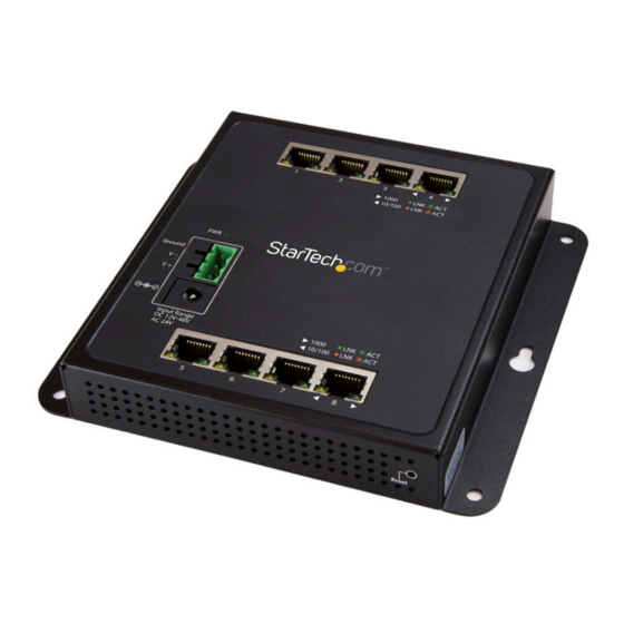
Introduction Product diagram RJ45 ports 1 to 4 Mounting hole Mounting hole Link and activity LED indicators (2 per port) Power LED indicator 3-pin terminal block Mounting hole Mounting hole DC power input RJ45 ports 5 to 8 Reset button (not pictured) Quick-start guide... -
Page 5: Package Contents
• 1 x DIN rail • 3 x DIN-rail screws • 8 x dust caps • 1 x quick-start guide Requirements • Ethernet port connection • RJ45 network cables Requirements are subject to change. For the latest requirements, please visit www.StarTech.com/IES81GW. Quick-start guide... -
Page 6: About The Led Indicators
About the LED indicators This network switch features a link and activity LED indicator for each of the eight RJ45 ports. There is an additional power LED located above the 3-pin terminal block. For more information about what the LED indicators signify, see the table below. Behavior Significance Illuminated yellow... -
Page 7: Reboot The Network Switch
Reboot the network switch The Reset button on the network switch is designed to reboot the network switch without turning off and turning on the power. • To reboot the network switch, press the Reset button. Reset to the default factory settings You can use the Reset button to reset the network switch to the following default factory settings: Default user name: admin... -
Page 8: Installation
Installation Install the enclosure on a wall 1. Hold the enclosure against the wall in the area that you want to install it, and use a pencil to trace the location of the four mounting holes onto the wall. 2. Use the mounting holes that you traced on the wall as a template and drill holes in the wall. -
Page 9: Install The Enclosure On A Magnetic Surface
Install the enclosure on a magnetic surface 1. Push each of the attaching pins into a locking pin. 2. Insert the attaching and locking pins into one of the mounting holes on the enclosure, through a washer, and into a magnet. Note: To prevent the magnets from becoming loose, make sure that you position the magnet so that the flat side is against the enclosure. -
Page 10: Mount The Enclosure To A Din Rail
Mount the enclosure to a DIN rail 1. With the flat side of the DIN rail positioned against the enclosure, line up the holes on the DIN rail with the holes on the enclosure. 2. Insert the DIN-rail screws through the DIN rail and into the enclosure. (figure 3) 3. -
Page 11: Technical Support
Limitation of Liability In no event shall the liability of StarTech.com Ltd. and StarTech.com USA LLP (or their officers, directors, employees or agents) for any damages (whether direct or indirect, special, punitive, incidental, consequential, or otherwise), loss of profits, loss of business, or any pecuniary loss, arising out of or related to the use of the product exceed the actual price paid for the product. - Page 12 StarTech.com is an ISO 9001 Registered manufacturer of connectivity and technology parts. StarTech.com was founded in 1985 and has operations in the United States, Canada, the United Kingdom and Taiwan servicing a worldwide market.
Need help?
Do you have a question about the IES81GW and is the answer not in the manual?
Questions and answers