
Subscribe to Our Youtube Channel
Related Manuals for Anita GARUDAN GPS/G-1507


Summary of Contents for Anita GARUDAN GPS/G-1507
- Page 1 User´s Manual GARUDAN GPS/G-1507 GARUDAN GPS/G-2010 GARUDAN GPS/G-3020 ANITA B, s.r.o. Hliníky 2068 680 01 Boskovice Czech Republic tel: +420 516 454 774, 516 453 496 fax: +420 516 452 751 e-mail: info@anita.cz...
- Page 2 ANITA © GPS/G serie...
- Page 3 ANITA © Catalogue 1. Specifications…………………………6 2. Description …………………………...7 3. Safety instruction book………………8 4. Safety installation……………………10 5. Electric device setting.………………10 6. Precaution before use ………………11 1)lubrication 2)needle installation 3)upper threading 4)hook threading 5)hook installation and removing 6)tension adjustment for upper thread and hook thread...
-
Page 4: Specification
ANITA © 1) SPECIFICATION Model 1507 2010 3020 GPS/G serie... - Page 5 ANITA © Sewing area 150x70 mm 200x100 mm 300x200 mm Max sewing 2800 spm 2800 spm 2300 spm speed (see table on page 27) (see table on page 27) (see table on page 27) Stitch length 0,1 – 12,7 mm No.
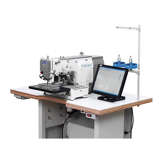
- Page 6 ANITA © Machine body Thread rack (7) Emergency switch Top feed board LCD control panel Control box Bottom feed board Power switch 3) SAFETY INSTRUCTION BOOK GPS/G serie...
- Page 7 ANITA © In this manual, “danger”,“ warning” and “attention” marks are shown on the point’s concerting safety issues. If not following its instruction, the person may be hurt and mechanical troubles may be caused as well. products Transportation should be done by the person who is familiar with safety transportation guide and rules.
- Page 8 ANITA © a) Safety labels: for precautions while operating. Safety devices b) Thread take-up lever: for preventing the body contact with thread taking up. c) Motor shielding cover: d) Hand guard plate: for keeping fingers away from needle. e) Power type label: for preventing getting an electric shock(grounding...
-
Page 9: Safety Installation
ANITA © For safety‘s sake, the warning marks are lapelled on the machine. Please Warning marks pay attention to the notes on warning marks when you operate the machine. One mark is on the control box and one is under the machine on positioning the stand. -
Page 10: Preparation Before Using
ANITA © 6) PREPARATION BEFORE USING 1. Lubricating Check the amount in the oil cup on the bracket Lubricate the hole on the top of the bracket. Fig. 1 Fig. 2 The machine should be lubricated first before its first use or reuse after a long period of... - Page 11 ANITA © 2. Needle installing Loosen the set screws on needle holder, fully insert the needle end into the needle socket in needle holder while keeping the needle slot facing front, then tighten it with the screws. Needle set screw Needle Fig.
- Page 12 ANITA © Installing and removing the shuttle case Hold Handle and insert the shuttle ending up clicking. Bobbin [Notice] case Before the shuttle is fully installed, starting machine will cause thread coil in a mess or make shuttle case flick out.
- Page 13 ANITA © 8. Adjusting pressure foot height A. Loosen Screw 1 Keep a height gap of 0.5mm between the pressure foot low tip and the sewing material, then tighten Screw [Notice] After adjusting the height of pressure foot, the treadle position should be ensured.
- Page 14 ANITA © 7) MECHANIC MAINTENANCE 1. Adjusting needle bar Loosen Screw at the lowest position of the needle holder, adjust the needle upper line to be in accordance with the needle holder socket line as the figure shows. Then tighten Screw.
- Page 15 ANITA © Fig.17 3. Adjusting bottom shaft gear and swing gear A. Loosen Screw 1 and 2. B. While rotating the upper shaft, turn the eccentric in the direction shown by the arrow to adjust the gear drive position. [Notice] When the swing gear is not positioned accurately, the machine will not run.
- Page 16 ANITA © 5. Adjust the height of feed board Loose the left and right two-sided screws(2) in driven-shelf ‘s up-down pole operation board (1) , operation board along the A direction put up the height of up-feed board (3) must be reduce, along the B direction put down the height of up-feed board (3) must be increase.
- Page 17 ANITA © Fig. 22 C. Adjust the press-feed adjust pole a) Loose position connect (plug ) board screw , make some distance between position connect board (4) and press-feet connect fix screw (3) . b) Loose screw (1), move the press-feet connect screw(2) to the right side of adjust pole, and then fix the press-feet connect screw(2) .
- Page 18 ANITA © 7. Adjust footplate part Fix screw , decrease the distance between press-feet left (1) and right (2) , make two footplates could press the axis nail in press-feet .if use thin material or the pressurer is less , move the electromagnetism - iron (5) along A position, the last close the screw .
- Page 19 ANITA © B) Interpose loose thread brake location a)Cancel loose thread replacement spring. b)Loosen loose thread brake , adjust the distance between adjust drive pole and loose line pin is 0.3mm, when push loose thread brake to right , the distance between adjust drive pole and loose line pin will be reduced , push it to left and the distance will be increased.
- Page 20 ANITA © Adjust the fittings of wiper mechanism A) The way of adjust wiper mechanism position a) When the distance between needle tine and needle board is 19.5mm , loose screw (1) and (2) in wiper mechanism ‘eddy axis b) After pressing the wiper drive brace (3) of...
- Page 21 ANITA © B) The way of adjust connect determent-organ [Notice] If no clearance between cut-thread cam roller and both side of cut-thread cam , may be cut-thread could not be achieved or machine could be locked. b) Put cut-thread cam roller inter the cut-thread cam active part, connect determent-organ screw touch the part (A) of cut-thread connect pole, and then fix screw.
- Page 22 ANITA © a) Be sure do not run cut-thread parts , loose the screw of cut-thread drive determent-organ , adjust clearance to 0.3mm between cut-thread drive and the concave of cut-thread drive determent- organ . b) (47)Screw fixed screw tightly.
- Page 23 ANITA © 11. Adjusting the manual pulley a) Align Gear Wheel (B) with the section of the manual pulley shaft, then tighten the screw. b)After Gear (A) meshing with Gear (B), tighten the screw. c)When the roller is aligning with the section...
- Page 24 ANITA © 13. X-Y X-Y origin setting A. X-axis origin setting a)Remove the X-cover of lower feed plate. Move the upper feed plate along X-axis to keep it pointing to the center. b) As the figure shows, loosen the two screw on the detecting sensor holder, locate the origin detecting plate of X-axis in the centre of the sensor.
-
Page 25: Troubleshooting
ANITA © Trouble shooting trouble cause remedy The fuse of power or circuit is Make sure if the fuse is short-cut short-cut of the main motor driver in Machine starts monitoring box and runs The feed bracket X or Y is... - Page 26 ANITA © The tension of thread take-up Adjust the tension and the motion spring is too large and its amount working volume is too big The tension of needle thread is Adjust the tension of needle not enough thread not well of...
- Page 27 ANITA © Table of max sewing speed 1507, 2010 Line stitch Zigzag stitch speed max stitch lenght speed max stitch lenght 2800 2,5mm 2000 2,5mm 2800 2000 2800 3,5mm 1800 3,5mm 2500 1600 2000 1500 1600 1200 1500 1000 1000...
- Page 28 ANITA © GPS/G serie...
Need help?
Do you have a question about the GARUDAN GPS/G-1507 and is the answer not in the manual?
Questions and answers