
Related Manuals for Anita GARUDAN GP-137-448 MH/L33


Summary of Contents for Anita GARUDAN GP-137-448 MH/L33
- Page 1 User´s Manual GP-137-448 MH/L33 GP-237-448 MH/L33 ANITA B, s.r.o. Průmyslová 2453/7 680 01 Boskovice Czech Republic tel: +420 516 454 774 +420 516 453 496 fax: +420 516 452 751 e-mail: info@anita.cz...
- Page 2 ANITA © All rights reserved Property of Anita B s.r.o. and protected by copyright. The use of this content without written permission is prohibited. Copyright © Anita B s r.o. (2015) GP-137-448 MH/L33, GP-237-448 MH/L33...
-
Page 3: Table Of Contents
ANITA © Content 1. SPECIFICATION ........................5 2. SAFETY MEASURES ....................... 6 3. COMMISSIONING THE MACHINE ..................7 4. PRECAUTION BEFORE USING ..................... 8 5. INSTRUCTION FOR THE DISPOSAL ..................8 6. THREADING OF UPPER THREAD ..................9 7. SETTING UPPER THREAD TENSION ................. 11 8. - Page 4 ANITA © 36. THE GAP BETWEEN NEEDLE AND HOOK SETTING ........... 41 37. HOOK HEIGHT SETTING ....................42 38. HOOK THREAD TIMING SETTING ................... 43 39. NEEDLE PROTECTED PLATE SETTING ................44 40. INNER HOOK DRIVING TIMING SETTING ..............45 41.
-
Page 5: Specification
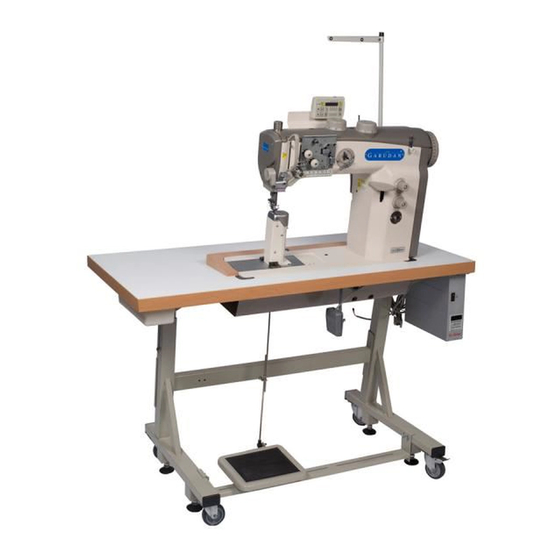
ANITA © 1. SPECIFICATION Model Usage Max speed Max stitch Needle system Presser foot length & size stroke GP-137-448 MH/L33 medium-heavy 2.500 135x17 (110-160) 20 mm GP-237-448 MH/L33 medium- heavy 2.500 135x17(110-160) 20 mm Weight: Complete: 110 kg Dimension: Complete: 55x120x120cm General description and usage: Twins needle sewing machine for regular sewing operations in the production of upholstery. -
Page 6: Safety Measures
ANITA © 2. SAFETY MEASURES Do not put the machine into operation until an appropriate preaparation is carried out by a specialist or an authorised person, and until you get acquainted with safety measures. 1. Any sewing machine may be operated only by a properly trained operator. -
Page 7: Commissioning The Machine
ANITA © Important notices Be careful! Never set off the machine without the belt cover, you could be heart. To avoid disorders and damages, i tis necessary to do these: • Before the first setting off, clean and oil the machine properly . -
Page 8: Precaution Before Using
5. INSTRUCTION FOR THE DISPOSAL When the machine isn´t possible to run because its technical life give it to the company ANITA B,s.r.o. ,for its disposal or you can give the machine to another company which is specialised for disposal of product. -
Page 9: Threading Of Upper Thread
ANITA © 6. THREADING OF UPPER THREAD Threading scheme Single needle machine Double needle machine GP-137-448 MH/L33, GP-237-448 MH/L33... - Page 10 ANITA © Threading of upper thread - Turn off the main switch! Threading may only be performed if the sewing machine is turned off. Threading of single needle machines - Insert the thread cones on the stand and lead the upper thread through the unwinder arm.
-
Page 11: Setting Upper Thread Tension
ANITA © 7. SETTING UPPER THREAD TENSION GP-137-448 MH/L33, GP-237-448 MH/L33... - Page 12 ANITA © Auxiliary thread tensioner If main tensioner 2 and additional tensioner 3 are open, still, small amount of sub- tension is needed. This sub-tension is regulated by auxiliary tensioner 1. This tensioner, at the same time, controls length of the thread ends after trimming (thread ends for next stitch).
-
Page 13: Setting Thread Regulator
ANITA © 8. SETTING THREAD REGULATOR Turn off main switch. The thread regulator may only be adjusted with the sewing machine switched off. The thread regulator controls the quantity of thread required for stitch formation. The thread regulator must be precisely adjusted for an optimum result. -
Page 14: Winding Of Hook Thread
ANITA © 9. WINDING OF HOOK THREAD Put the thread cone on the thread stand and conduct the thread through the unwinder arm. Pass the thread through thread guide 1 and tensioner 2. Pull the thread beginning behind the tear-off knife 3 and tear it off. Insert the empty bobbin on the winder. -
Page 15: Exchange Of Hook Thread Bobbin
ANITA © 10. EXCHANGE OF HOOK THREAD BOBBIN Turn off the main switch. Hook thread bobbin may only be replaced if is machine is turned off. Taking out the empty bobbin Raise the flap 1 and take out the empty bobbin. -
Page 16: Setting Hook Thread Tension
ANITA © 11. SETTING HOOK THREAD TENSION Turn off the main switch. Lower thread tension may only be adjusted only if the machine is switched off. Adjustment of tension spring 2 Set the tension spring 2 by the regulating screw 1. -
Page 17: Changing The Needle In 1-Needle Machines
ANITA © 12. CHANGING THE NEEDLE IN 1-NEEDLE MACHINES Turn off the main switch. Needle may only be changed if the machine is switched off. Turn the handwhell until the needle bar reached its upper end position. Loosen screw 2. Take out needle from the needle bar 1. -
Page 18: Changing The Needle In 2-Needle Machines
ANITA © 13. CHANGING THE NEEDLE IN 2-NEEDLE MACHINES Turn off the main switch. Needle may only be changed if the machine is switched off. Turn the handwhell until the needle bar 1 reached its upper end position. Loosen screw 3. Take out needle from the needle bar holder 2. -
Page 19: Lifting Of Presser Feet
ANITA © 14. LIFTING OF PRESSER FEET Presser feet can be lifted electro-pneumatically by actuating the pedal 2 or by pressing knee lever 1. Mechanic lifting of presser feet (knee lever) In order to move material, correcting its position, press the knee lever to the right. -
Page 20: Locking The Presser Feet In The Upper Position
ANITA © 15. LOCKING THE PRESSER FEET IN THE UPPER POSITION Turn the lever 1 downwards. The presser feet are locked in their utmost upper position. Turn the lever 1 upwards. The presser feet are released. Or Lift the presser feet pneumaticaly by the foot pedal or mechanically by the knee lever . -
Page 21: Setting The Presser Foot Stroke
ANITA © 17. SETTING THE PRESSER FOOT STROKE Sewing machines are always equipped with 2 dials for setting the presser foot stroke. Left dial 2 controls standard presser foot stroke in the range of 1 to 9mm. Right dial 1 controls increased presser foot stroke in the range of 1 to 9mm. -
Page 22: Setting The Stitch Length
ANITA © 18. SETTING THE STITCH LENGTH Sewing machines equipped with 2 knobs for setting the stitch length. This enables operator to sew with 2 different lengths of stitch which can be activated via special key (see following chapter) Stitch length can be set by knobs 1 and 2 on the machine arm. -
Page 23: Key Panel On The Machine Arm
ANITA © 19. KEY PANEL ON THE MACHINE ARM Function Quick presser feet stroke adjustment Light is on = maximum presser feet stroke Light is off = minimum presser feet stroke Additional thread tension Light is on = additional thread tension is activated... -
Page 24: Sewing
ANITA © 20. SEWING Operation steps and sewing functions: Sewing operation Operation / Instructions Before start of sewing: Initial position Pedal at stop position Sewing machine at a halt Needle is up Presser feet are down Place the sewn material at the beginning... - Page 25 ANITA © Sewing of backtack in the middle of Press the lever of the stitch regulator 4 sewing downwards. The machine sews in backwards direction (backtack) as long as the stitch regulator lever is pressed. Required speed is controlled by the pedal.
-
Page 26: Main Shaft Positioner (1/2)
ANITA © 21. MAIN SHAFT POSITIONER (1/2) 3 screw (10) of the cam (4) need tight on the flat (11) of the shaft (11). GP-137-448 MH/L33, GP-237-448 MH/L33... -
Page 27: Main Shaft Positioner (2/2)
ANITA © 22. MAIN SHAFT POSITIONER (2/2) Use the stipulate (1) 3 mm one end go through the positioner hole (5) of the machine, inserting the notch (3) of the cam (4), loose the fixed screw (6) of the hand wheel (2) removing the and wheel (2) make the dialing „0“... -
Page 28: Neddle Position Setting
ANITA © 23. NEDDLE POSITION SETTING Use the fixture (1) with outer presser foot (2), inner presser foot (3), needle bar (4), and make the needle bar (4) to pre-setting position. GP-137-448 MH/L33, GP-237-448 MH/L33... -
Page 29: Feed Dog Relative With Needle Position Setting
ANITA © 24. FEED DOG RELATIVE WITH NEEDLE POSITION SETTING Release the screw (1),(2),(3) move the feeding block (6) and make the needle (4) to center the feed dog (7) hole (5) , then tie the screw (1),(2),(3). (notice: make the gap (8) as small as possible). -
Page 30: Feeding Transfer Position Setting
ANITA © 25. FEEDING TRANSFER POSITION SETTING Release the screws (1),(2),(3) move the block (6) and make the block (6) position same as shaft (7) slot (5). Tie the screws 3,2,1 in an order, remember to reduce the gap as small as possible when tie the screws. -
Page 31: Normal Stitch And Reverse Stitch Feeding Position Setting
ANITA © 26. NORMAL STITCH AND REVERSE STITCH FEEDING POSITION SETTING Release the screw (1), use tool to rotate the top of the rope (2), make the plate (3) and link (4) as same as (5), (like the diagram). Release the screw (6), rotate the eccentric wheel (7), make the notch (8) become horizontal, tie the screw (6). -
Page 32: Feeding Setting
ANITA © 27. FEEDING SETTING Rotate the knob (1), make the scale „4“ to aligned with the mark (3). Release the screw (5) and take off the knob (6), use a tool to rotate the top of the rope (7), make the rope (7) to touch plate (8), rote the scale plate (9) and make the scale „4“... -
Page 33: Feeding Time Adjustment
ANITA © 28. FEEDING TIME ADJUSTMENT Make hand wheel scale „190“ aligned with the mark (5), sbake the manual reverse stitch knob (1) up and down, adjust the eccentric (7) until the connected unit (6) without any movement, tie the screw (4). -
Page 34: Needle Bar Vertical Position Setting
ANITA © 29. NEEDLE BAR VERTICAL POSITION SETTING Use the fixture (1) to make the needle bar (2) to pre-setting position, rotate the hand wheel and make the scale „190“ aligned with the mark (3). Release the screw (7), make the distance between the link (4) center (5) and surface of the machine be 123,5 mm, tie the screws (7), (8). -
Page 35: Feed Dog Position Setting
ANITA © 30. FEED DOG POSITION SETTING Rotate hand wheel (1) and make the scale „190“ aligned with the mark (2). Move the feed dog (3) and make needle (4) on the center of the hole (5), tie the screw (6). -
Page 36: Feed Dog Movement Timing Setting
ANITA © 31. FEED DOG MOVEMENT TIMING SETTING Rotate driving eccentric (2), make the screw (1) aligned with the screw (3) of feeding eccentric (4). Tie the screw (1) (adjust the feeding eccentric). GP-137-448 MH/L33, GP-237-448 MH/L33... -
Page 37: Feed Dog Height Relative With Needle Plate Setting
ANITA © 32. FEED DOG HEIGHT RELATIVE WITH NEEDLE PLATE SETTING Rotate hand wheel (1) and make the scale „190“ aligned with the mark (2), feed dog (3) is 0,8 mm higher than needle plate (4), tie the screw (5). -
Page 38: Counterweight Block Setting
ANITA © 33. COUNTERWEIGHT BLOCK SETTING Rotate hand wheel (1) and make the scale „210“ aligned with the mark (2), adjust the screw (3) of the counterweight block and make the screw (3) horizontal with the picture. GP-137-448 MH/L33, GP-237-448 MH/L33... -
Page 39: The Mechanical Of Presser Foot Amount Interaction Setting
ANITA © 34. THE MECHANICAL OF PRESSER FOOT AMOUNT INTERACTION SETTING Move the shaft (2), make the touch point (3) and positioned screw (4) aligned, move the block (1) and put it in the center of the space, tie the screw (6). (notice: don´t touch shaft (2)), then press the fixed shaft (7), tie the screw (5). -
Page 40: Interaction Timing Setting
ANITA © 35. INTERACTION TIMING SETTING Rotate hand wheel (1) and make the scale „95“ aligned with the mark (2). Use tool to rotate the block (5) and adjust the driving eccentric (3) at the same time until the connected unit (6) without any movement, tie the screw (4). -
Page 41: The Gap Between Needle And Hook Setting
ANITA © 36. THE GAP BETWEEN NEEDLE AND HOOK SETTING Rotate the knob (1), make the scale „0“ to aligned with the mark (3), release the screw (4), (5), (6), move the hook set (7) and make the gap 0,1 mm between needle (10) and hook tip (9), tie the screw (6). -
Page 42: Hook Height Setting
ANITA © 37. HOOK HEIGHT SETTING Release the screw (1) and move hook (2), make the gap 1~1,2 mm between hook positioned slot surface and needle plate bottom surface, tie the screw (1). GP-137-448 MH/L33, GP-237-448 MH/L33... -
Page 43: Hook Thread Timing Setting
ANITA © 38. HOOK THREAD TIMING SETTING Rotate the knob (1), make the scale „0“ to aligned with the mark (3), put the fixture (4) 5 mm into slot (6) of the eccentric (5). Rotate hook (7), make the hook tip (8) aligned with center of the needle (9), tie the screw (13). -
Page 44: Needle Protected Plate Setting
ANITA © 39. NEEDLE PROTECTED PLATE SETTING Use allen key (1) and adjust the screw (2), make the needle protected plate and needle just touched. (The gap between needle (3) and hook tip (5) would be 0,1 mm). GP-137-448 MH/L33, GP-237-448 MH/L33... -
Page 45: Inner Hook Driving Timing Setting
ANITA © 40. INNER HOOK DRIVING TIMING SETTING Rotate the hand wheel (1), make the scale „75“ to aligned with the mark (2), release the screw (3) and make the alley key (4) to be vertical with the bottom of the hook, tie the screw (3). -
Page 46: Thread And Hook Position Relation
ANITA © 41. THREAD AND HOOK POSITION RELATION Rotate the hand wheel (1), make the scale „310“ to aligned with the mark (2), (thread 3 is going to go into hook positioned slot 4), then the distance between A surface of positioned... -
Page 47: Thread And Hook Position Relation
ANITA © 42. THREAD AND HOOK POSITION RELATION Rotate the hand wheel (1), make the scale „340“ to aligned with the mark (2), then the distance between inner hook opener (4) and inner hook (3) must be more than 1,2 mm, release the screw 5 if necessary. -
Page 48: Thread Trimmer Timing Setting
ANITA © 43. THREAD TRIMMER TIMING SETTING Rotate the hand wheel (1), maket he scale „65“ to aligned with mark (2), adjut the angle of the eccentric (5), maket he flexible knife (5) go according to the arrow direction, tie the screw (4). -
Page 49: Thread Trimmer Position Setting
ANITA © 44. THREAD TRIMMER POSITION SETTING The flexible knife (1) relative position with fixed knife (2), the height adjustment: release the screw (3) and adjust the screw (4), then tie the screw (3). The stroke adjustment of flexible knife: release the screw (5) and move it to the axis (6) direction, the stroke will become small and the opposite side will become bigger, tie the screw (5) after adjustment. -
Page 50: Presser Foot Interaction Amount Setting
ANITA © 45. PRESSER FOOT INTERACTION AMOUNT SETTING Rotate the hand wheel (1), mke the scale „90“ to aligned with the mark (2), move the link (3) forvard to R direction until touch the inner presser foot (4) and needle plate, tie the screw (6). -
Page 51: Presser Foot Driving Handle Setting
ANITA © 46. PRESSER FOOT DRIVING HANDLE SETTING The gap between foot driving handle (1) and holder (2) is0,5 mm, tie the screw (3). GP-137-448 MH/L33, GP-237-448 MH/L33... -
Page 52: The Thread And Thread Spring Tension Setting
ANITA © 47. THE THREAD AND THREAD SPRING TENSION SETTING Release the screw 1 and move the thread rack (2) to left, then the thread amount become more, it will become less when move to right, tie the screw after adjustment. Release the screw (3), rotate the supporter (4) clockwise, the thread spring stroke becomes less, rotate counterclockwise it would become more, tie the screw (3) adjustment (8mm for reference). -
Page 53: Bobbin Thread Winding Setting
ANITA © 48. BOBBIN THREAD WINDING SETTING Adjust the screw (1) make teh adjustace gap ot the winding plate (2) 6,5 mm, then make the A surface of the winding plate (2) and the edge of bobbin case 3 aligned, release the screw (4), adjust the block (5) position, make it touch the steel plate (7) as the diagram (6), tie the screw (4). -
Page 54: Maintenance
ANITA © 49. MAINTENANCE Cleaning work Turn off the main switch. Cleaning can only be carried out if the machine is turned off. The maintenance work must be carried out in accordance with the intervals defined in charts (see column operation period). - Page 55 ANITA © Driving unit Clean the motor fan sieve Remove sewing dust and thread (e.g. by compressed air gun) remains from the openings. Check the tension of V-belt If pressed by finger in the middle, the V-belt must bend down by approximately 10mm.
-
Page 56: Lubrication By Oil
ANITA © 50. LUBRICATION BY OIL For lubrication of the machine use only oil recommended by manufacturer/supplier or oil with the following specification: Viscosity at 40°C = 10mm/s Flash point = 150°C Maintenance work Description Operation period Machine head is equipped with wick Lubrication of head feed oil central lubrication system.
Need help?
Do you have a question about the GARUDAN GP-137-448 MH/L33 and is the answer not in the manual?
Questions and answers