
Related Manuals for Beckhoff KL400 Series


Summary of Contents for Beckhoff KL400 Series
- Page 1 Documentation KL400x Single-, Dual and Four-Channel Analog Output Terminals, (0V...10V) Version: Date: 2017-10-20...
-
Page 3: Table Of Contents
Table of contents Table of contents 1 Foreword .............................. 5 Notes on the documentation...................... 5 Safety instructions .......................... 6 Documentation issue status...................... 7 2 Product overview............................ 8 KL400x - introduction........................ 8 KL400x - technical data ........................ 9 Basic function principles ....................... 10 3 Mounting and wiring .......................... 11 Instructions for ESD protection ..................... - Page 4 Table of contents Version: 4.0 KL400x...
-
Page 5: Foreword
The TwinCAT Technology is covered, including but not limited to the following patent applications and patents: EP0851348, US6167425 with corresponding applications or registrations in various other countries. ® EtherCAT is registered trademark and patented technology, licensed by Beckhoff Automation GmbH, Germany Copyright © Beckhoff Automation GmbH & Co. KG, Germany. -
Page 6: Safety Instructions
All the components are supplied in particular hardware and software configurations appropriate for the application. Modifications to hardware or software configurations other than those described in the documentation are not permitted, and nullify the liability of Beckhoff Automation GmbH & Co. KG. Personnel qualification This description is only intended for trained specialists in control, automation and drive engineering who are familiar with the applicable national standards. -
Page 7: Documentation Issue Status
Foreword Documentation issue status Version Comment • Migration • Update Technical data • Structure update • Chapters KS2000 configuration software and Access from the user program added Firmware (FW) and hardware (HW) versions Documen- KL4001 KL4002 KL4004 tation, Version The firmware and hardware versions (delivery state) can be found in the serial number printed on the side of the terminal. -
Page 8: Product Overview
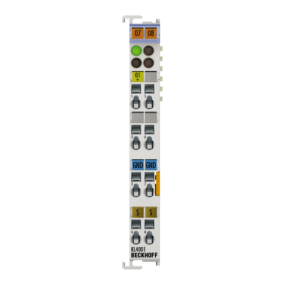
Product overview Product overview KL400x - introduction Fig. 1: KL4001, KL4002, KL4004 The analog KL400x output terminals generate signals in the range 0 V to 10 V. The voltage is supplied to the process level with a resolution of 12 bits, and is electrically isolated. The output channels of the Bus Terminals have a common ground potential. -
Page 9: Kl400X - Technical Data
Product overview KL400x - technical data Technical data KL4001 KL4002 KL4004 Number of outputs Power supply for the electronics via the K-Bus Signal voltage 0 V…10 V Load > 5 kΩ (short-circuit-proof) Accuracy ± 0.5 LSB linearity error, ± 0.5 LSB offset error Output error < ± 0.10 % (at 0°C to +55°C) < ±0.1 % of the end value < ± 0.75 % (when the extended temperature range is used) -
Page 10: Basic Function Principles
Product overview Basic function principles The analog KL400x output terminals generate signals in the range 0 V to 10 V with a resolution of 12 bits (4095 steps). The output voltage is electrically isolated from the K-bus. The LEDs indicate the operating state of the associated terminal channels. •... -
Page 11: Mounting And Wiring
Each assembly must be terminated at the right hand end with an EL9011 bus end cap, to ensure the protection class and ESD protection. Fig. 2: Spring contacts of the Beckhoff I/O components Installation on mounting rails Risk of electric shock and damage of device! -
Page 12: Fig. 3 Attaching On Mounting Rail
Mounting and wiring Assembly Fig. 3: Attaching on mounting rail The Bus Coupler and Bus Terminals are attached to commercially available 35 mm mounting rails (DIN rails according to EN 60715) by applying slight pressure: 1. First attach the Fieldbus Coupler to the mounting rail. 2. -
Page 13: Fig. 4 Disassembling Of Terminal
Mounting and wiring Disassembly Fig. 4: Disassembling of terminal Each terminal is secured by a lock on the mounting rail, which must be released for disassembly: 1. Pull the terminal by its orange-colored lugs approximately 1 cm away from the mounting rail. In doing so for this terminal the mounting rail lock is released automatically and you can pull the terminal out of the bus terminal block easily without excessive force. -
Page 14: Fig. 5 Power Contact On Left Side
Mounting and wiring Fig. 5: Power contact on left side Possible damage of the device Note that, for reasons of electromagnetic compatibility, the PE contacts are capacitatively coupled to the mounting rail. This may lead to incorrect results during insulation testing or Attention to damage on the terminal (e.g. -
Page 15: Installation Instructions For Enhanced Mechanical Load Capacity
Mounting and wiring Installation instructions for enhanced mechanical load capacity Risk of injury through electric shock and damage to the device! Bring the Bus Terminal system into a safe, de-energized state before starting mounting, disassembly or wiring of the Bus Terminals! WARNING Additional checks The terminals have undergone the following additional tests:... -
Page 16: Fig. 6 Standard Wiring
Mounting and wiring • The High Density Terminals (HD Terminals) include electronics and connection level in a single enclosure and have advanced packaging density. Standard wiring (ELxxxx / KLxxxx) Fig. 6: Standard wiring The terminals of ELxxxx and KLxxxx series have been tried and tested for years. They feature integrated screwless spring force technology for fast and simple assembly. -
Page 17: Wiring
Mounting and wiring The Bus Terminals from these series with 16 terminal points are distinguished by a particularly compact design, as the packaging density is twice as large as that of the standard 12 mm Bus Terminals. Massive conductors and conductors with a wire end sleeve can be inserted directly into the spring loaded terminal point without tools. -
Page 18: Shielding
Mounting and wiring See the following table for the suitable wire size width. Terminal housing ELxxxx, KLxxxx ESxxxx, KSxxxx Wire size width (single core wires) 0.08 ... 2.5 mm 0.08 ... 2.5 mm Wire size width (fine-wire conductors) 0.08 ... 2.5 mm 0,08 ... 2.5 mm Wire size width (conductors with a wire end sleeve) 0.14 ... -
Page 19: Kl4001, Kl4002 - Connection And Led Description
Mounting and wiring KL4001, KL4002 - connection and LED description Risk of injury through electric shock and damage to the device! Bring the Bus Terminals system into a safe, de-energized state before starting mounting, disassembly or wiring of the Bus Terminals! WARNING Fig. 10: KL4001, KL4002 - connection and LEDs KL4001 connection... -
Page 20: Kl4004 - Connection And Led Description
Mounting and wiring KL4004 - connection and LED description Risk of injury through electric shock and damage to the device! Bring the Bus Terminals system into a safe, de-energized state before starting mounting, disassembly or wiring of the Bus Terminals! WARNING Fig. 11: KL4004 - connection and LEDs KL4004 connection... -
Page 21: Atex - Special Conditions (Standard Temperature Range)
• EN 60079-0:2012+A11:2013 • EN 60079-15:2010 Marking The Beckhoff fieldbus components with standard temperature range certified for potentially explosive areas bear one of the following markings: II 3G KEMA 10ATEX0075 X Ex nA IIC T4 Gc Ta: 0 … 55°C II 3G KEMA 10ATEX0075 X Ex nC IIC T4 Gc Ta: 0 … 55°C KL400x Version: 4.0... -
Page 22: Atex - Special Conditions (Extended Temperature Range)
• EN 60079-0:2012+A11:2013 • EN 60079-15:2010 Marking The Beckhoff fieldbus components with extended temperature range (ET) certified for potentially explosive areas bear the following marking: II 3G KEMA 10ATEX0075 X Ex nA IIC T4 Gc Ta: -25 … 60°C II 3G KEMA 10ATEX0075 X Ex nC IIC T4 Gc Ta: -25 … 60°C Version: 4.0... -
Page 23: Atex Documentation
Notes about operation of the Beckhoff terminal systems in potentially explo- sive areas (ATEX) Pay also attention to the continuative documentation Note Notes about operation of the Beckhoff terminal systems in potentially explosive areas (ATEX) that is available in the download area of the Beckhoff homepage http:\\www.beckhoff.com! KL400x... -
Page 24: Configuration Software Ks2000
Configuration Software KS2000 Configuration Software KS2000 KS2000 - Introduction The KS2000 configuration software permits configuration, commissioning and parameterization of bus couplers, of the affiliated bus terminals and of Fieldbus Box Modules. The connection between bus coupler / Fieldbus Box Module and the PC is established by means of the serial configuration cable or the fieldbus. Fig. 12: KS2000 configuration software Configuration You can configure the Fieldbus stations with the Configuration Software KS2000 offline. - Page 25 Configuration Software KS2000 Commissioning The KS2000 software facilitates commissioning of machine components or their fieldbus stations: Configured settings can be transferred to the fieldbus modules by means of a download. After a login to the terminal station, it is possible to define settings in couplers, terminals and Fieldbus Box modules directly online. The same high-level dialogs and register access are available for this purpose as in the configuration phase.
-
Page 26: Access From The User Program
Access from the user program Access from the user program KL400x - terminal configuration The terminal can be configured and parameterized via the internal register structure. Each terminal channel is mapped in the Bus Coupler. Mapping of the terminal data in the Bus Coupler memory may differ, depending on the Bus Coupler type and the set mapping configuration (e.g. Motorola/Intel format, word alignment etc.). -
Page 27: Fig. 15 Mapping In The Interbus Coupler - Example For Kl4002
Access from the user program • KL4001: 2 bytes of output data • KL4002: 4 bytes of output data • KL4004: 8 bytes of output data Parameterization via the fieldbus is not possible. If the control and status byte is to be used, the KS2000 configuration software is required. -
Page 28: Mapping In The Bus Coupler
Access from the user program Mapping in the Bus Coupler As already described in the Terminal Configuration section, each Bus Terminal is mapped in the Bus Coupler. This mapping is usually done with the default setting in the Bus Coupler / Bus Terminal. The KS2000 configuration software or a master configuration software (e.g. ComProfibus or TwinCAT System Manager) can be used to change this default setting. -
Page 29: Kl4001
Access from the user program 5.2.1 KL4001 Default mapping for: CANopen, CANCAL, DeviceNet, ControlNet, Modbus, RS232 and RS485 coupler Conditions Word offset High byte Low byte Complete evaluation: no Ch0 D1 Ch0 D0 Motorola format: no Word alignment: any Default mapping for: Profibus and Interbus Coupler Conditions Word offset High byte... -
Page 30: Kl4002
Access from the user program 5.2.2 KL4002 Default mapping for: CANopen, CANCAL, DeviceNet, ControlNet, Modbus, RS232 and RS485 coupler Conditions Word offset High byte Low byte Complete evaluation: no Ch0 D1 Ch0 D0 Motorola format: no Ch1 D1 Ch1 D0 Word alignment: any Default mapping for: Profibus and Interbus Coupler Conditions... -
Page 31: Kl4004
Access from the user program 5.2.3 KL4004 Default mapping for: CANopen, CANCAL, DeviceNet, ControlNet, Modbus, RS232 and RS485 coupler Conditions Word offset High byte Low byte Complete evaluation: no Ch0 D1 Ch0 D0 Motorola format: no Ch1 D1 Ch1 D0 Word alignment: any Ch2 D1 Ch2 D0... -
Page 32: Register Overview
Access from the user program Complete evaluation The terminal is mapped with control and status byte. Motorola format Motorola or Intel format can be set. Word alignment The terminal is positioned on a word boundary in the Bus Coupler. Ch n CB Control byte for channel n (appears in the process image of the outputs). - Page 33 Access from the user program • R0 to R4: reserved • R5: Raw DAC value (Y_dac) The 12-bit value transferred to the D/A converter is called raw DAC value. It is calculated from the process data via the manufacturer and user scaling. •...
- Page 34 Access from the user program ◦ High byte: reserved ◦ Low byte: Offset value (0 to 255) • R18: Hardware compensation - gain (A_a) This register is used for hardware gain compensation (8-bit digital potentiometer) of the terminal. The register is transferred to the hardware after each processor reset or with each write access to R17. ◦...
-
Page 35: Control And Status Byte
Access from the user program • R34: User scaling - gain (A_w) 16 bit signed integer*2 [0x0100] This register contains the scaling factor of the user straight-line equation (Eq. 1.4 [} 10]). The straight- line equation is enabled via register R32 [} 34]. •... -
Page 36: Register Communication
Access from the user program 5.5.2 Register communication Register access via process data exchange • Bit 7=1: Register mode If bit 7 of the control byte is set, the first two bytes of the user data are not used for process data exchange but written into the register set of the terminal or read from it. -
Page 37: Examples Of Register Communication
Access from the user program Sample 1: Reading of register 8 in the BK2000 with a KL4002 and the end terminal: If the following bytes are transferred from the controller to the terminal, Byte Byte 3 Byte 2 Byte 1 Byte 0 Name DataOUT 1... -
Page 38: Example 2: Writing To An User Register
Access from the user program • The terminal returns the firmware version 0x3341 in the input data word (byte 1 and byte 2). This is to be interpreted as an ASCII code: ◦ ASCII code 0x33 represents the digit 3 ◦... - Page 39 Access from the user program Input Data (answer of the bus terminal) Byte 0: Status byte Byte 1: DataIN1, high byte Byte 2: DataIN1, low byte 0x9F (1001 1111 0x12 0x35 Explanation: • The terminal returns the value of the control byte as a receipt in the status byte. •...
- Page 40 Access from the user program Input Data (answer of the bus terminal) Byte 0: Status byte Byte 1: DataIN1, high byte Byte 2: DataIN1, low byte 0xA0 (1010 0000 0x00 0x02 Explanation: • The terminal returns the value of the control byte as a receipt in the status byte. •...
-
Page 41: Appendix
Beckhoff's branch offices and representatives Please contact your Beckhoff branch office or representative for local support and service on Beckhoff products! The addresses of Beckhoff's branch offices and representatives round the world can be found on her internet pages: http://www.beckhoff.com You will also find further documentation for Beckhoff components there. - Page 42 List of illustrations List of illustrations Fig. 1 KL4001, KL4002, KL4004......................Fig. 2 Spring contacts of the Beckhoff I/O components................. Fig. 3 Attaching on mounting rail ......................Fig. 4 Disassembling of terminal......................Fig. 5 Power contact on left side......................Fig. 6 Standard wiring..........................
Need help?
Do you have a question about the KL400 Series and is the answer not in the manual?
Questions and answers