Table of Contents

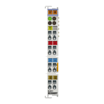
Summary of Contents for Beckhoff KL4011
- Page 1 Operating instructions for KL4011 and KL4012 Single- and Two-Channel Analog Output Terminals Signal range: 0 to 20 mA KL4021 and KL4022 Single- and Two-Channel Analog Output Terminals Signal range: 4 to 20 mA Version: 3.1 Date: 2006-10-20...
-
Page 2: Table Of Contents
Table of contents Table of contents 1. Foreword Notes on the documentation Safety Instructions 2. Technical data 3. Connection KL4011 and KL4021 KL4012 and KL4022 4. Functional description 5. Terminal configuration 6. Register Description General Description of Registers Terminal-specific register description... -
Page 3: Foreword
In addition, the general delivery conditions of the company Beckhoff Automation GmbH apply. Copyright © This documentation is copyrighted. Any reproduction or third party use of this publication, whether in whole or in part, without the written permission of Beckhoff Automation GmbH, is forbidden. KL401x and KL402x... -
Page 4: Safety Instructions
All the components are supplied in particular hardware and software configurations appropriate for the application. Modifications to hardware or software configurations other than those described in the documentation are not permitted, and nullify the liability of Beckhoff Automation GmbH. Description of safety symbols The following safety symbols are used in this documentation. -
Page 5: Technical Data
Technical data Technical data Technical data KL4011 KL4021 KL4012 KL4022 Number of outputs Power supply 24 V via the power contacts (alternatively 15 V with power supply unit terminal KL9515) Signal voltage 0 ... 20 mA 4 ... 20 mA 0 ... -
Page 6: Connection
Connection Connection KL4011 and KL4021 KL4012 and KL4022 KL401x and KL402x... -
Page 7: Functional Description
Functional description The analog output terminals - KL4011 and KL4012 generate signals in the range between 0 and 20 mA. - KL4021 and KL4022 generate signals in the range between 4 and 20 mA. with a resolution of 12 bits (4095 increments). The output current is electrically isolated from the K-Bus. -
Page 8: Terminal Configuration
If the control and status byte are not evaluated, the terminals occupy 2 bytes per channel: • KL4011 and KL4021: 2 bytes of output data • KL4012 and KL4022: 4 bytes of output data Example for KL4012 and KL4022:... -
Page 9: Register Description
The BK4000 Interbus Coupler maps the terminals in the delivery state with 2 bytes per channel: • KL4011 and KL4021: 2 bytes of output data • KL4012 and KL4022: 4 bytes of output data Parameterisation via the fieldbus is not possible. If the control and status byte is to be used, the KS2000 configuration software is required. - Page 10 Register Description The main features of the internal data structure are the same for all the intelligent terminals. This data area is organised as words and comprises 64 registers. The important data and parameters of the terminal can be read and set through this structure. It is also possible for functions to be called by means of corresponding parameters.
- Page 11 Register Description R13: Data type register Data type register 0x00 Terminal with no valid data type 0x01 Byte array 0x02 Structure 1 byte n bytes 0x03 Word array 0x04 Structure 1 byte n words 0x05 Double word array 0x06 Structure 1 byte n double words 0x07 Structure 1 byte 1 double word 0x08...
-
Page 12: Terminal-Specific Register Description
Register Description Terminal-specific register description Process variables R0 to R4: reserved R5: Raw DAC value (Y_dac) The 12-bit value transferred to the D/A converter is called raw DAC value. It is calculated from the process data via the manufacturer and user scaling. - Page 13 Register Description User parameters R32: Feature register: [0x0006] The feature register specifies the operating modes of the terminal. Feature bit Description of the operating mode Bit 0 User scaling (1.2) active [0] Bit 1 Manufacturer scaling (1.1) active [1] Bit 2 Watchdog timer active [1] In the delivery state, the watchdog timer is switched on.
-
Page 14: Control And Status Byte
Register Description Control and Status byte Control byte for process The control byte is transmitted from the controller to the terminal. It can be data exchange used Gain and offset - in register mode (REG = 1 ) or compensation - during process data exchange (REG = 0 The control byte can be used to carry out gain and offset compensation for the terminal (process data exchange). - Page 15 Register Description To the bus coupler K-Bus User data Control-/ 2 or mors bytes status byte If control bit 7=0: input/output If control bit 7=1: register- C/S-bit 7 configuration If control bit 7=1: adress in the control bit 0-5 Terminal´s If control bit 6=0: read register set If control bit 6=1: write...
-
Page 16: Appendix
If the terminals are fully evaluated, they occupy memory space in the input and output process image. The following tables provide information about the terminal mapping, depending on the conditions set in the Bus Coupler. KL4011 and KL4021 Default mapping for: Conditions Word offset... - Page 17 Appendix KL4012 and 4022 Default mapping for: Conditions Word offset High byte Low byte CANopen, CANCAL, Complete evaluation: Ch0 D1 Ch0 D0 DeviceNet, ControlNet, Motorola format: Ch1 D1 Ch1 D0 Modbus, RS232, RS485 Word alignment: Default mapping for: Conditions Word offset High byte Low byte Profibus, Interbus...
-
Page 18: Register Table
Appendix Register Table These registers exist once for each channel. Address Denomination Default Storage medium value reserved 0x0000 reserved 0x0000 Raw DAC value variable Diagnostic register not used 0x0000 Command register not used 0x0000 Terminal type e.g. 4012 Software version number 0x???? Multiplex shift register 0x0218/0130... -
Page 19: Support And Service
BECKHOFF products and system solutions. BECKHOFF Support Support offers you comprehensive technical assistance, helping you not only with the application of individual BECKHOFF products, but also with other, wide-ranging services: • world-wide support •...


Need help?
Do you have a question about the KL4011 and is the answer not in the manual?
Questions and answers