
Related Manuals for Beckhoff KL4132


Summary of Contents for Beckhoff KL4132
- Page 1 Documentation KL4132 Dual-channel analog output terminal, -10 V to +10 V, 16 Bit Version: Date: 2017-11-16...
-
Page 3: Table Of Contents
Connection system...................... 15 3.4.2 Wiring .......................... 17 3.4.3 Shielding .......................... 18 KL4132 - connection and LED description ................... 19 ATEX - Special conditions (standard temperature range) ............ 20 ATEX Documentation ........................ 21 4 Configuration Software KS2000...................... 22 KS2000 - Introduction ........................ 22 5 Access from the user program ...................... 24 KL4132 - Terminal configuration.................... - Page 4 Table of contents Version: 3.0 KL4132...
-
Page 5: Foreword
The TwinCAT Technology is covered, including but not limited to the following patent applications and patents: EP0851348, US6167425 with corresponding applications or registrations in various other countries. ® EtherCAT is registered trademark and patented technology, licensed by Beckhoff Automation GmbH, Germany Copyright © Beckhoff Automation GmbH & Co. KG, Germany. -
Page 6: Safety Instructions
All the components are supplied in particular hardware and software configurations appropriate for the application. Modifications to hardware or software configurations other than those described in the documentation are not permitted, and nullify the liability of Beckhoff Automation GmbH & Co. KG. Personnel qualification This description is only intended for trained specialists in control, automation and drive engineering who are familiar with the applicable national standards. -
Page 7: Documentation Issue Status
• Chapters KS2000 configuration software and Access from the user program added Firmware (FW) and hardware (HW) versions Documentation, KL4132 version The firmware and hardware versions (delivery state) can be found in the serial number printed on the side of the terminal. -
Page 8: Product Overview
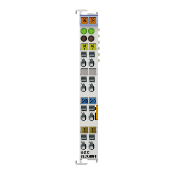
Fig. 1: KL4132 The KL4132 analog output terminal generates signals in the range from -10 V to +10 V. The voltage is supplied to the process level with a resolution of 16 bits, and is electrically isolated. The output channels of a Bus Terminal have a common ground potential. -
Page 9: El4132 - Technical Data
Product overview EL4132 - Technical data Technical Data KL4132 Number of outputs Power supply via the K-Bus Signal current -10 V…+10 V Load > 5 kΩ Accuracy < ±0.1 % (of the full scale value) Resolution 16 bits Electrical isolation 500 V (K-Bus / signal voltage) Conversion time ~ 1.5 ms... -
Page 10: Basic Function Principles
Basic function principles The KL4132 analog output terminal generates signals in the range from -10 V to +10 V. The terminal supplies the output voltage with a resolution of up to 16 bits. The output voltage is output electrically isolated from the terminal bus level. -
Page 11: Mounting And Wiring
Each assembly must be terminated at the right hand end with an EL9011 bus end cap, to ensure the protection class and ESD protection. Fig. 2: Spring contacts of the Beckhoff I/O components Installation on mounting rails Risk of electric shock and damage of device! -
Page 12: Fig. 3 Attaching On Mounting Rail
Note flict with the fixing bolts of the mounting rail. To mount the mounting rails with a height of 7.5 mm under the terminals and couplers, you should use flat mounting connections (e.g. countersunk screws or blind rivets). Version: 3.0 KL4132... -
Page 13: Fig. 4 Disassembling Of Terminal
PE power contact The power contact labeled PE can be used as a protective earth. For safety reasons this contact mates first when plugging together, and can ground short-circuit currents of up to 125 A. KL4132 Version: 3.0... -
Page 14: Fig. 5 Power Contact On Left Side
Power Feed Terminals can be released and pulled at least 10 mm from the group of terminals. Risk of electric shock! The PE power contact must not be used for other potentials! WARNING Version: 3.0 KL4132... -
Page 15: Installation Instructions For Enhanced Mechanical Load Capacity
• The terminals of ELxxxx and KLxxxx series with standard wiring include electronics and connection level in a single enclosure. • The terminals of ESxxxx and KSxxxx series feature a pluggable connection level and enable steady wiring while replacing. KL4132 Version: 3.0... -
Page 16: Fig. 6 Standard Wiring
The overview and nomenclature of the product names for ESxxxx and KSxxxx series has been retained as known from ELxxxx and KLxxxx series. High Density Terminals (HD Terminals) Fig. 8: High Density Terminals Version: 3.0 KL4132... -
Page 17: Wiring
Do not turn the screwdriver or move it alternately (don't toggle). 2. The wire can now be inserted into the round terminal opening without any force. 3. The terminal point closes automatically when the pressure is released, holding the wire securely and permanently. KL4132 Version: 3.0... -
Page 18: Shielding
Wire size width (conductors with a wire end sleeve) 0.14 ... 0.75 mm Wire size width (ultrasonically “bonded" conductors) only 1.5 mm Wire stripping length 8 ... 9 mm 3.4.3 Shielding Shielding Encoder, analog sensors and actors should always be connected with shielded, twisted paired wires. Note Version: 3.0 KL4132... -
Page 19: Kl4132 - Connection And Led Description
Mounting and wiring KL4132 - connection and LED description Risk of injury through electric shock and damage to the device! Bring the Bus Terminals system into a safe, de-energized state before starting mounting, disassembly or wiring of the Bus Terminals! WARNING Fig. 10: KL4132 - connection and LEDs... -
Page 20: Atex - Special Conditions (Standard Temperature Range)
• EN 60079-0:2012+A11:2013 • EN 60079-15:2010 Marking The Beckhoff fieldbus components with standard temperature range certified for potentially explosive areas bear one of the following markings: II 3G KEMA 10ATEX0075 X Ex nA IIC T4 Gc Ta: 0 … 55°C II 3G KEMA 10ATEX0075 X Ex nC IIC T4 Gc Ta: 0 … 55°C Version: 3.0... -
Page 21: Atex Documentation
Notes about operation of the Beckhoff terminal systems in potentially explo- sive areas (ATEX) Pay also attention to the continuative documentation Note Notes about operation of the Beckhoff terminal systems in potentially explosive areas (ATEX) that is available in the download area of the Beckhoff homepage http:\\www.beckhoff.com! KL4132... -
Page 22: Configuration Software Ks2000
Fieldbus Box modules with the aid of which settings can be modified easily. Alternatively, you have full access to all internal registers of the bus couplers and intelligent terminals. Refer to the register description for the meanings of the registers. Version: 3.0 KL4132... - Page 23 • Process values can be specified in the output image for commissioning of the output modules. All possibilities in the online mode can be used in parallel with the actual fieldbus mode of the terminal station. The fieldbus protocol always has the higher priority in this case. KL4132 Version: 3.0...
-
Page 24: Access From The User Program
BK3000 Profibus Coupler For the BK3000 Profibus coupler, the master configuration should specify for which terminal channels the control and status byte is to be inserted. If the control and status byte are not evaluated, the KL4132 occupies 4 bytes input data: Fig. 13: Mapping in the Profibus coupler –... -
Page 25: Fig. 14 Mapping In The Interbus Coupler - Example For Kl4132
BK4000 Interbus Coupler The BK4000 Interbus Coupler maps the KL4132 in delivery state with 4 bytes of output data (2 bytes of user data per channel). Parameterization via the fieldbus is not possible. If the control and status byte is to be used, the KS2000 configuration software is required. -
Page 26: Mapping In The Bus Coupler
If the terminals are fully evaluated, they occupy memory space in the input and output process image. The following tables provide information about how the terminals map themselves in the Bus Coupler, depending on the parameters set. Version: 3.0 KL4132... -
Page 27: Kl4132
Access from the user program 5.2.1 KL4132 Default mapping for: CANopen, CANCAL, DeviceNet, ControlNet, Modbus, RS232 and RS485 coupler Conditions Word offset High byte Low byte Complete evaluation: no Ch0 D1 Ch0 D0 Motorola format: no Ch1 D1 Ch1 D0... -
Page 28: Register Description
• R8: Terminal type The terminal type in register R8 is needed to identify the terminal. • R9: Software version (X.y) The software version can be read as a string of ASCII characters. Version: 3.0 KL4132... - Page 29 • R20: Manufacturer scaling - gain (A_h) 16 bit unsigned integer*2 [0x0100] This register contains the scale factor of the manufacturer's equation of the straight line (Eq. 1.1 [} 10]). The straight-line equation is enabled via register R32 [} 30]. 1 corresponds to register value 0x0100. KL4132 Version: 3.0...
-
Page 30: Control And Status Byte
R31 [} 30] so that the terminal calibration can be carried out. The gain and offset of the terminal can then be calibrated. The parameter will only be saved permanently once the code word is reset! Version: 3.0 KL4132... - Page 31 : up Bit 0 : down Status byte in process data exchange (REG=0) The status byte is transferred from the terminal to the controller. In the KL4132, the status byte has no function for the process data exchange. KL4132 Version: 3.0...
-
Page 32: Register Communication
2 data bytes. (The BK2000 is an exception: here, an unused data byte is inserted after the control or status byte, and the register value is therefore placed on a word boundary). Version: 3.0 KL4132... -
Page 33: Examples Of Register Communication
Access from the user program Sample 1: Reading of register 8 in the BK2000 with a KL4132 and the end terminal: If the following bytes are transferred from the controller to the terminal, Byte Byte 3 Byte 2 Byte 1... -
Page 34: Example 2: Writing To An User Register
• Bit 0.6 not set means: reading the register. • Bits 0.5 to 0.0 specify the register number 31 with 01 1111 • The output data word (byte 1 and byte 2) has no meaning during read access. Version: 3.0 KL4132... - Page 35 • Bit 0.6 not set means: reading the register. • Bits 0.5 to 0.0 indicate register number 32 with 10 0000 • The output data word (byte 1 and byte 2) has no meaning during read access. KL4132 Version: 3.0...
- Page 36 • The terminal returns a value as a receipt in the status byte that differs only in bit 0.6 from the value of the control byte. • The input data word (byte 1 and byte 2) is of no importance after the write access. Any values still displayed are invalid! Version: 3.0 KL4132...
-
Page 37: Appendix
Beckhoff's branch offices and representatives Please contact your Beckhoff branch office or representative for local support and service on Beckhoff products! The addresses of Beckhoff's branch offices and representatives round the world can be found on her internet pages: http://www.beckhoff.com You will also find further documentation for Beckhoff components there. - Page 38 KL4132 - connection and LEDs ....................Fig. 11 KS2000 configuration software....................Fig. 12 Mapping in the Interbus coupler – example for KL4132 .............. Fig. 13 Mapping in the Profibus coupler – example for KL4132 .............. Fig. 14 Mapping in the Interbus coupler – example for KL4132 ..............
Need help?
Do you have a question about the KL4132 and is the answer not in the manual?
Questions and answers