Table of Contents

Related Manuals for IDEAL TP12KSC-DX


Summary of Contents for IDEAL TP12KSC-DX
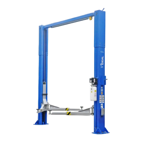
- Page 1 TP12KSC-DX Two Post Clear Floor Automotive Lift 12,000 lb. Capacity (3,000 lbs. Max Capacity per Arm) Installation & Operation Manual IMPORTANT!! READ MANUAL THOROUGHLY BEFORE INSTALLING, OPERATING, SERVICING OR MAINTAINING LIFT July 2018-A...
-
Page 2: Table Of Contents
Please note that your warranty can be voided if you do not read the manual and understand its content. If you have any questions, concerning operation, safety or application of your lift, please consult your distributor. PRODUCT IDENTIFICATION IMPORTANT SAVE THESE INSTRUCTIONS TP12KSC-DX July 2018-A... -
Page 3: Owner / Employer Obligations
Guide for Frame Engaging Lifts in a conspicuous location in the lift area convenient to the operator. 6. The Owner/Operator shall provide necessary lockout/tag out means for energy sources per ANSI Z244.1-1982 (R1993), Safety Requirements for the Lockout/Tag out of Energy Sources, before beginning any lift repairs and maintenance. TP12KSC-DX July 2018-A... -
Page 4: Important Safety Instructions
11. Keep the area around the lift clear of obstacles. 12. Never override the self-returning lift controls. 13. Use safety stands when removing or installing heavy vehicle components. 14. Avoid excessive rocking of the vehicle when it is on the lift. TP12KSC-DX July 2018-A... -
Page 5: Location
ATTENTION! This lift is intended for indoor installation only. It is prohibited to install this product outdoors. Operating environment temperature range should be 41 – 104 ° F (5 – 40 ° C). Failure to adhere will result in decertification, loss of warranty, and possible damage to the equipment. TP12KSC-DX July 2018-A... -
Page 6: Safety Decals
These Decals Must Be Applied to Lift. NOTE: SOME IMAGES IN THIS MANUAL ARE GENERIC AND MAY NOT RESEMBLE THE LIFT YOU HAVE PURCHASED. REFERENCE: AUTOMOTIVE LIFT INSTITUTE, Inc. CAUTION RELEASE ALL LATCHES BEFORE LOWERING LIFT MAXIMUM CAPACITY 12,000 LBS. TP12KSC-DX July 2018-A... -
Page 7: Important Information
Uniform Building Code (UBC) and/or International Building Code (IBC). When required, it is recommended to contact a qualitied engineer to address the specific UBC and/or IBC code requirements. TP12KSC-DX July 2018-A... -
Page 8: Product Information
1. PRODUCT INFORMATION 1.1 Product Description The TP12KSC-DX 2-post hydraulic lift is a surface mounted, frame contact lift incorporating the latest safety technologies. Designed and manufactured for a lifting capacity of 12,000 lbs. (Max 3,000 lbs. per Lifting Arm) and is fully capable for lifting vehicles, vans, light & heavy trucks by safely holding them in an elevated position. - Page 9 Figs. 1 & 2 Elevation & Floor Layout Fig. 1 - Elevation View TP12KSC-DX July 2018-A...
- Page 10 AND LOCATE THE POWER SIDE ON THE PASSENGER SIDE OF THE VEHICLE WHEN LOADED ON THE LIFT, IN ORDER TO SAVE STEPS DURING OPERATION. ENSURE TO POSITION OVERHEAD LIMIT SWITCH BOX ASSEMBLY ON SAME SIDE AS THE MAINSIDE COLUMN WITH POWER UNIT. SEE INSTALLATION INSTRUCTIONS FOR DETAILS. TP12KSC-DX July 2018-A...
-
Page 11: Installation
Do not use an impact wrench to tighten! Tighten the nut, two or three turns on average after the concrete has cured (28-day cure). If the concrete is very hard only one or two turns may be required. TP12KSC-DX July 2018-A... - Page 12 • 1-1/8” socket • 13/16” open end wrench • Level (18” minimum length) • Vise grips • Tape measure • Funnel • Hoist or Forklift (optional) • Two 12’ step ladders • 1/4” drive ratchet with 5/16” socket TP12KSC-DX July 2018-A...
- Page 13 A. Connect column uprights / extensions to each column using M10 bolts, washers and nuts. DUE TO HEAVY WEIGHT OF COLUMN ASSEMBLY, IT IS HIGHLY RECOMMENDED TO USE A HOIST OR FORKLIFT TO ASSIST IN STANDING THE COLUMNS TO AN UPRIGHT POSTION. TP12KSC-DX July 2018-A...
- Page 14 6. Install Overhead Beam & Limit Switch Bar (Figs. 3, 4 & 5) A. Ensure the cable pulleys are assembled onto shafts with spacers prior to attaching overhead beam to top of columns, as shown below in Fig 3. Fig. 3 TP12KSC-DX July 2018-A...
- Page 15 B. The base of the column may vary from the preliminary layout, as it is more important that the column be perpendicular to the floor and parallel to the other column. C. Install the anchor bolts and shim the base as described in Step 5. TP12KSC-DX July 2018-A...
- Page 16 Use vise grips to hold the cable end, but be very careful not to damage the threads. CARRIAGES MUST REMAIN AT THE SAME COLUMN LOCK HEIGHT POSITION WHILE CABLES ARE BEING TIGHTENED. FAILURE TO DO WILL CAUSE THE CARRIAGES SAFETY LATCHES TO BE OUT OF SYNC. TP12KSC-DX July 2018-A...
- Page 17 Fig. 7 Route hose through top of power unit bracket until the end of the longest hose comes down through the backside of the power unit bracket, as shown in Figs. 8 & 9. TP12KSC-DX July 2018-A...
- Page 18 Connect medium length hose (with 90 degree fitting) to main side cylinder, ensuring to route through leg gussets, as shown in Fig. 7. Route hose up to T-fitting and tighten. Install Hose Covers on sides of columns, using provided hardware. (See Exploded View at back of Manual for location details.) TP12KSC-DX July 2018-A...
- Page 19 & clamp, as shown in (Fig. 11a & 11b). Fig. 11a Fig. 11b Off Side Column Main Side Column (Use Set Screw & Clamp to secure Cable Wiring to Safety Latches) TP12KSC-DX July 2018-A...
- Page 20 C. Route and adjust the cable tension so that when the handle is pressed down, both latches will be released. D. Install covers for both latch devices on Off Side & Main Side columns, using the provided screws. (Figs. 12a & 12b) Fig. 12a Fig. 12b Off Side Column Main Side Column TP12KSC-DX July 2018-A...
- Page 21 Electrical Wiring must comply with local code. Protect each circuit with time delay fuse or circuit breaker. For 208V-230V single phase, use 20 amp fuse. Never operate the motor in line voltage less than 208VAC as motor damage may occur. TP12KSC-DX July 2018-A...
- Page 22 F. Raise the vehicle to full height and lower the carriages onto the safety latches. Lower the vehicle to the floor. G. After cycling the lift ten times with a vehicle on it, recheck the tightness of the anchors to at least 110 ft-lbs. The Lift is now ready for Operation. TP12KSC-DX July 2018-A...
-
Page 23: Operation
DO NOT hammer pin down, as this will damage the restraint gear teeth. c. Raise vehicle until the wheels clear the floor, then release the START button. d. Check support adapters for secure contact at vehicle manufacturer recommended lift points. TP12KSC-DX July 2018-A... - Page 24 After the lift is lowered down onto the ground, remove adapters from under vehicle and swing arms to full drive- thru position before moving vehicle out. IF LIFT IS NOT OPERATING PROPERLY, DO NOT USE UNTIL ADJUSTMENT OR REPAIRS ARE MADE BY QUALIFIED LIFT SERVICE PERSONNEL. TP12KSC-DX July 2018-A...
- Page 25 Load the vehicle with the center of gravity midway between adapters. Unusual vehicles, such as limousines, RV’s, and long wheelbase vehicles, may not be suitable for lifting on this equipment. If necessary, consult with your iDEAL Automotive Equipment representative or contact the vehicle manufacturer. TP12KSC-DX...
-
Page 26: Inspection & Maintenance Instructions
Also, see ANSI/ALI ALOIM booklet for periodic Inspection Checklist and Maintenance Log Sheet. ALWAYS REPLACE WORN PARTS WITH GENUINE, AUTHORIZED PARTS. For Parts & Service Assistance Please contact iDEAL Automotive Equipment @ Toll Free: 877-588-9337 (Also see Additional Information next two pages) TP12KSC-DX... - Page 27 * Lay is the distance measured, parallel to the rope axis, in which a single strand makes one complete turnaround the rope axis, or the wires make a complete turnaround the axis of the strand. Also, reference ANSI/ALI ALOIM standard for more information on wire rope cable inspection. TP12KSC-DX July 2018-A...
-
Page 28: Exploded Views & Parts Lists
For assistance, please contact iDEAL Automotive Equipment @ Toll Free: 877-588-9337 TP12KSC-DX July 2018-A... - Page 29 5. Exploded View / Parts List TP12KSC-DX July 2018-A...
- Page 30 Parts List For Parts & Service Assistance Please contact iDEAL Automotive Equipment @ Toll Free: 877-588-9337 ITEM Tux P/N M-Ref P/N DESCRIPTION TP12KSC-DX-001.1 SJ13-12000-A00 Offside Column TP12KSC-DX-002 SJ01-12002-000 Shim TP12KSC-DX-003 SJ01-12003-ETL Anchor Bolt, 3/4" x 7" TP12KSC-DX-004.1 SJ13-00002-A00 Height Adaptor 2.6"...
- Page 31 TP12KSC-DX-042 SJ01-00012-ETL Limit Switch TP12KSC-DX-043 SJ13-00027-000 Limit Switch Wiring TP12KSC-DX-044 SJ13-00020-000 Hydraulic Hose, 8-1/4" TP12KSC-DX-045 SJ13-00018-001 Hydraulic Hose, 33' 1" TP12KSC-DX-046 SJ01-00016-000 T-Fitting TP12KSC-DX-047 SJ13-00019-000 Hydraulic Hose, 71" TP12KSC-DX-048 5301-00006-000 Flat Washer, D6 49-1 TP12KSC-DX-049.1 SJ13-00007-A00 Latch Cover 49-2 TP12KSC-DX-049.2...
- Page 32 TP12KSC-DX-099 SJ12-00004-000 Spring #2 TP12KSC-DX-100 5114-06020-000 Screw, M6 x 20mm TP12KSC-DX-101 SJ13-00061-A00 Latch Release Cable TP12KSC-DX-102 SJ12-00008-000 Small Bracket TP12KSC-DX-103 SJ12-00005-000 Pulley, D30 x 10mm TP12KSC-DX-104 SJ12-00015-000 Pin #1 TP12KSC-DX-105 SJ12-00007-000 Latch Release Handle TP12KSC-DX-106 SJ12-00011-000 Handle Knob, D40 x M10...
-
Page 33: Troubleshooting Guide
Locking latches do not engage. Possible cause: Solution: 1. Latch shafts rusted. 1. Oil latch mechanism. Grease the shaft. 2. Latch spring broken. 2. Replace broken spring. 3. Latch cable needs adjustment. 3. Adjust clamps at cable end TP12KSC-DX July 2018-A... -
Page 34: Warranty Policy
Limited One-Year Warranty: Tuxedo Distributors, LLC (iDEAL) offers a limited one-year warranty to the original purchaser of Lifts and Wheel Service equipment in the United States and Canada. Tuxedo will replace, without charge, any part found defective in materials or workmanship under normal use, for a period of one year after purchase.
Need help?
Do you have a question about the TP12KSC-DX and is the answer not in the manual?
Questions and answers