Sign In
Upload
Manuals
Brands
Texas Instruments Manuals
Motherboard
DP83TD510E-EVM
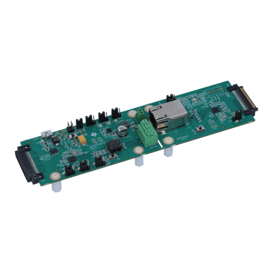
Texas Instruments DP83TD510E-EVM Manuals
Manuals and User Guides for Texas Instruments DP83TD510E-EVM. We have
1
Texas Instruments DP83TD510E-EVM manual available for free PDF download: User Manual
Texas Instruments DP83TD510E-EVM User Manual (44 pages)
Brand:
Texas Instruments
| Category:
Motherboard
| Size: 3 MB
Table of Contents
Figure 1-1. DP83TD510E-EVM Consists of Two Pcb's: DP83TD510E Single-Pair-Ethernet Board and DP83822I Media-Converter Board
1
Table of Contents
2
1 Definitions
5
Table 1-1. Terminology
5
2 Introduction
6
Key Features
6
Figure 2-1. DP83TD510E-EVM - Top Side
6
Block Diagram
7
Figure 2-2. DP83TD510E-EVM - Bottom Side
7
Figure 2-3. DP83TD510E-EVM Block Diagram
7
Operation - Quick Setup
8
Figure 2-4. Wide-Vin Supply Connection
8
Figure 2-5. DP83TD510E External Supply Connection and Jumpers
9
3 Board Setup Details
10
Power Supply Selection
10
Master and Slave Mode Selection - DP83TD510E
11
Figure 3-1. DP83TD510E USB Power Supply
11
Clock Selection - DP83TD510E
12
SMI Connection
12
Cable Assembly
12
LED Indication
12
Serial Management Interface
12
Configuration Options
12
Table 3-1. DP83822 Bootstrap Resistor Designation and Suggested Bootstrap Resistor Values
13
Table 3-2. DP83TD510E Bootstrap Resistor Designation and Suggested Bootstrap Resistor Values
13
4 Software
14
MSP430 Driver
14
USB-2-MDIO Software
14
5 Schematics
15
Main Power Schematic
16
Figure 5-1. DP83TD510E-EVM Main Power
16
Main Block Schematic
17
Figure 5-2. DP83TD510E-EVM Main Block
17
Interface Schematic
18
Figure 5-3. DP83TD510E-EVM Interface
18
Analog Front End Schematic
19
Figure 5-4. DP83TD510E-EVM AFE
19
Figure 5-5. DP83822I Media Converter AFE
20
Coms Schematic
21
Figure 5-6. DP83TD510E-EVM Coms
21
Header Board
22
Figure 5-7. DP83TD510E-EVM Break-Out Connector
22
Hardware Schematic
23
Figure 5-8. DP83TD510E-EVM Hardware
23
6 Layout
24
Top Overlay
24
Top Layer Mask
24
Top Layer
24
Figure 6-1. Top Overlay
24
Figure 6-2. Top Layer Mask
24
Figure 6-3. Top Layer
24
Ground Layer 1
25
Signal Layer
25
Power Layer
25
Figure 6-4. Ground Layer 1
25
Figure 6-5. Signal Layer
25
Figure 6-6. Power Layer
25
Ground Layer 2
26
Bottom Layer
26
Bottom Layer Mask
26
Figure 6-7. Ground Layer 2
26
Figure 6-8. Bottom Layer
26
Figure 6-9. Bottom Layer Mask
26
Bottom Overlay
27
Board Assembly
27
Figure 6-10. Bottom Overlay
27
Figure 6-11. Top Assembly
27
Figure 6-12. Bottom Assembly
28
Figure 6-13. Drill Drawing
28
Figure 6-14. Board Dimensions
28
7 Bill of Materials
29
Table 7-1. Bill of Materials
29
8 Revision History
38
Advertisement
Advertisement
Related Products
Texas Instruments DP83TD510E-PODL-EVM
Texas Instruments DP83TC812EVM-MC
Texas Instruments DP83TG721EVM-MC
Texas Instruments DP83TG720-EVM-AM2
Texas Instruments DP83561EVM
Texas Instruments DP83826EVM
Texas Instruments DP83867
Texas Instruments DP83869
Texas Instruments DP83825EVM
Texas Instruments DP83867-EVM-AM
Texas Instruments Categories
Motherboard
Control Unit
Microcontrollers
Computer Hardware
Calculator
More Texas Instruments Manuals
Login
Sign In
OR
Sign in with Facebook
Sign in with Google
Upload manual
Upload from disk
Upload from URL