Table of Contents
Advertisement
Quick Links
Advertisement
Table of Contents

Related Manuals for Danfoss EM-PMI375


Summary of Contents for Danfoss EM-PMI375
- Page 1 User Guide Motor / Generator EM-PMI375 www.danfoss.com...
- Page 2 User Guide EM-PMI375 Revision history Table of revisions Date Changed November 2021 Updated user guide 0202 © Danfoss | November 2021 BC265856307805en-000202...
-
Page 3: Table Of Contents
Connection diagram................................43 Cable gland assembly and power line connection....................45 Low voltage connections...............................49 Grounding connections................................. 54 Anti-condensation heater connections..........................56 Operation Operation conditions..................................58 Condition monitoring during operation..........................58 Recommended lubricants................................58 Recommended coolants................................59 Emergency operation...................................59 © Danfoss | November 2021 BC265856307805en-000202 | 3... - Page 4 User Guide EM-PMI375 Contents Maintenance Regular maintenance................................... 61 Cleaning......................................62 Bearings and lubrication................................62 Cooling system maintenance..............................66 Dismounting Troubleshooting Aftersales Service policy....................................69 Service parts.....................................69 Disposal Storage, installation and maintenance checklists © Danfoss | November 2021 BC265856307805en-000202...
-
Page 5: Intended Use Of The User Guide
User Guide EM-PMI375 General information This user guide is the installation, operation and maintenance user guide for the EM-PMI375-T200, EM- PMI375-T500, EM-PMI375-T800 and EM-PMI375-T1100 electric machines. Intended use of the user guide This user guide contains instructions necessary to safely and properly handle, install, operate and maintain the electric machine. - Page 6 PT-100 in bearings Plug-in connector Anti-condensation heaters None None +HEAT1 One anti-condensation 230VAC/65W heater Marine classification No marine classification +CL1 ABS American Bureau of Shipping +CL2 BV Bureau Veritas +CL3 +CL4 LR Lloyd’s Register +CL5 RINA © Danfoss | November 2021 BC265856307805en-000202...
- Page 7 12 x PT100 (two wire) in windings (Not surveillance available with +LVB1 option) Bearing temperature sensor * None +BTMP1 PT100 in bearings Plug-in connector Anti-condensation heaters None +HEAT1 One anti-condensation 230VAC/65W heater © Danfoss | November 2021 BC265856307805en-000202 | 7...
- Page 8 User Guide EM-PMI375 General information EM-PMI375-T500 options (continued) Variant Code Description Additional information Marine classification No marine classification +CL1 ABS American Bureau of Shipping +CL2 BV Bureau Veritas +CL3 +CL4 LR Lloyd’s Register +CL5 RINA EM-PMI375-T800 options Variant Code Description...
- Page 9 User Guide EM-PMI375 General information EM-PMI375-T800 options (continued) Variant Code Description Additional information Rotation sensor (resolver) None No resolver +RES1 Resolver In-built non contacting resolver, 6-pole pair +RES2 Double resolver 2 x In-built non contacting resolver, 6-pole pair Winding temperature...
-
Page 10: Conformity According To Standards
User Guide EM-PMI375 General information EM-PMI375-T1100 options (continued) Variant Code Description Additional information Bearing insulation Non-insulated bearings Non-insulated bearings +BIN Insulated bearing in N-end Insulated bearing in N-end +BIA Insulated bearing in both Insulated bearing in both ends ends Shaft grounding... -
Page 11: Warranty
56 mm and higher - Measurement, evaluation and limits of vibration severity. Warranty Danfoss offers warranty against defects in workmanship and materials for its products for a period of twelve (12) months from commissioning or eighteen months (18) from delivery (Incoterms-EXW), whichever occurs first. -
Page 12: Responsibility Of The Manufacturer
Duty type according to the IEC60034; Duty with non-periodic load and speed variations Responsibility of the manufacturer Danfoss is responsible for the safety, reliability and performance of the electric machine only if: • Handling, mounting, installation, operation and maintenance are done by qualified and authorized personnel. -
Page 13: Safety Information
It indicates a hot device that could cause burns to a person. The symbol also indicates that the device should be placed and installed so that contact with its potentially hot surface is not possible. © Danfoss | November 2021 BC265856307805en-000202 | 13... -
Page 14: Personal Protective Equipment
The electric machine has at least one PT100 temperature sensor in the windings. The amount of the sensors depend on the options chosen. The temperature signal(s) can be read out from the measurement 14 | © Danfoss | November 2021 BC265856307805en-000202... -
Page 15: Electromagnetic Compatibility (Emc)
It is the responsibility of the installer to make sure that the equipment or system into which the product is incorporated complies with the EMC legislation of the country of use. Within the European Union, equipment into which this product is incorporated must comply with the EMC Directive 2014/30/EU. © Danfoss | November 2021 BC265856307805en-000202 | 15... -
Page 16: Product Overview
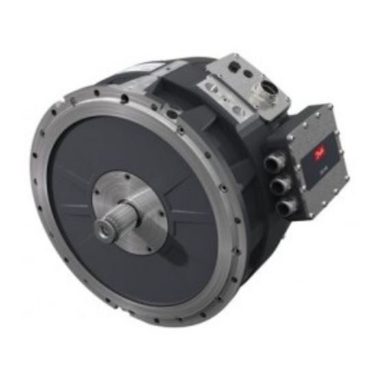
Machine structure designed to be able to produce high starting torques (instant torque to non- moving wheel). • Optimized speed range to meet most common gear ratios used in heavy mobile machinery. EM-PMI375-T200 16 | © Danfoss | November 2021 BC265856307805en-000202... - Page 17 User Guide EM-PMI375 Product overview EM-PMI375-T500 EM-PMI375-T800 © Danfoss | November 2021 BC265856307805en-000202 | 17...
-
Page 18: Intended Use Of The Electric Machine
Operating and performing maintenance for the electric machine without appropriate personal protective equipment. • Using electric machine parts like frame, shaft end or terminal box for climbing or for support for other structures. 18 | © Danfoss | November 2021 BC265856307805en-000202... -
Page 19: Used Technology
See Figure below illustrating the magnet topology of the electric machine. The Figure shows the principle only, and is not an exact illustration of the structure. Machine topology Electric machine stator and stator windings Electric machine rotor © Danfoss | November 2021 BC265856307805en-000202 | 19... -
Page 20: System Introduction
Permanent magnets in the rotor System introduction Danfoss provides electric drive trains for applications in heavy mobile work machines, marine vessels and buses. The drive trains include all essential components for converting from traditional to hybrid electric (HEV) or electric vehicle (EV) solutions. Danfoss technology saves fuel and lowers emission and noise levels. -
Page 21: Connections And Interfaces
There can also be a male shaft or male shaft + flange connection in the N-end of the machine, depending on the option (+NE1 or +NE2). Bearing temperature sensors (Option +BTMP1). Air ventilation plug. © Danfoss | November 2021 BC265856307805en-000202 | 21... -
Page 22: Rating Plate
Electric machine product family: EM-PMI or EM-PME Electric machine type code and options Serial No. Serial number Rated voltage (phase-to-phase AC) Rated current (AC) Rated power (S9) according to IEC60034-1 Rated speed Rated torque (S9) at rated speed 22 | © Danfoss | November 2021 BC265856307805en-000202... -
Page 23: Tightening Torques
Mounting bolts for D-end attachment 40 Nm Mounting bolts for N-end attachment (support or auxiliary components) 30 Nm Connection box mounting screws 7 Nm Connection box cover plate screws 4 Nm Cable lug 15 Nm © Danfoss | November 2021 BC265856307805en-000202 | 23... - Page 24 User Guide EM-PMI375 Product overview Tightening torques to use unless otherwise noted 10.9 12.9 Thread 24 | © Danfoss | November 2021 BC265856307805en-000202...
-
Page 25: Design Principles
The value of the insulation lifetime expectancy is a calculated value and it is not tested in practice. The insulation of the electric machine has the following lifetime expectancy. © Danfoss | November 2021 BC265856307805en-000202 | 25... -
Page 26: Inverter
If the electric machine is driven with an inverter from a supplier other than Danfoss Editron, the electric machine performance may differ from rated values. The optimum performance of the electric machine is obtained with Danfoss Editron inverters. -
Page 27: Mounting Structure
AUX DC - The main machine power driving parameters are shown in the machine rating plate. For more information, contact Danfoss representative. You can connect one of the temperature signals (from the low voltage connector) to the temperature surveillance pin in the inverter and make sure that the inverter has the machine temperature protection feature activated. -
Page 28: Shaft Alignment And Load
With angular misalignment, the shafts are at an angle to each other. Figures below illustrate the parallel and angular misalignment. Parallel alignment of the shaft and mating structure 28 | © Danfoss | November 2021 BC265856307805en-000202... - Page 29 For more information, see document DOC-000454. Calculate the relevant values with the help of the document. Contact Danfoss service at https://danfosseditron.zendesk.com/hc/en-gb or send email to editron.service@danfoss.com to obtain the document. © Danfoss | November 2021 BC265856307805en-000202 | 29...
- Page 30 User Guide EM-PMI375 Design principles External shaft forces of the electric machine 30 | © Danfoss | November 2021 BC265856307805en-000202...
-
Page 31: Transportation And Storage
Do not touch the electrical terminals when the rotor is rotated. The electrical terminals have dangerous voltage during rotation. Contact Danfoss representative if the rotor can not be rotated. Remove the transportation supports of the electric machine. - Page 32 See the electric machine rating plate for weight information. Lift the electric machine using the correct lifting lugs/eyes only. Do not go under a lifted load. Lifting slings cannot touch the electric machine during the lifting. 32 | © Danfoss | November 2021 BC265856307805en-000202...
-
Page 33: Storage
The storage should be dry, dust free and vibration free. • Treat the unprotected electric machine surfaces such as the shaft-end and flanges against corrosion. Seal the cable exit holes and cooling bores for storage. © Danfoss | November 2021 BC265856307805en-000202 | 33... -
Page 34: Extended Storage
Rotate the shaft of the electric machine once a month. Keep the electric machine in its installation position while in storage. For example, vertically installed electric machines should be stored in vertical position. 34 | © Danfoss | November 2021 BC265856307805en-000202... -
Page 35: Installation
Only trained and qualified personnel familiar with the relevant safety requirements can work with the electric machine. Use correct personal protective equipment when you are near the electric machine. Read the instructions in this user guide before you install the electric machine. © Danfoss | November 2021 BC265856307805en-000202 | 35... -
Page 36: Required Tools
If the electric machine is in continuous use, it is recommended to do the insulation resistance test three or four times a year. The reference value of 150 MΩ must be exceeded in room temperature. Contact Danfoss representative if the reference value is not exceeded. Reference value of 150 MΩ has to be exceeded at reference ambient temperature 25°C (measured with 500 V... - Page 37 It is in some cases possible to make an exception from the limitations of the mounting positions. Document Allowed bearing loads for EM-PMI machines DOC-000454 gives more information about this. Contact Danfoss to obtain the document. See Figures below for mounting limitations of the electric machine.
-
Page 38: Mounting The Electric Machine
Further products which may be recommended are Molycote, Metaflux, Never Seeze, Optimol and similar. 5. Attach the mounting bolts. For steel housing the minimum length of the bolt is 35 mm and for aluminum housing 40 mm. (40 mm and 45 mm for EM-PMI375-T800). 38 | ©... - Page 39 Mounting bolts (12 pcs of DIN912 M10). Not included in the delivery. Shaft (male) in the N-end of the electric machine with option NE2 is DIN5480W50x2x24x8f. Vertical assembly In vertical assembly, follow the Steps given in the previous Section Horizontal assembly. © Danfoss | November 2021 BC265856307805en-000202 | 39...
- Page 40 3 Shaft of the electric machine; spline structure of the shaft (DIN5480 W50x2x24x8f) 4 D-end flange (SAE3). Use mounting bolts (12 pcs of DIN912 M10, not included in the delivery). Additional mounting points (1), 12 total 40 | © Danfoss | November 2021 BC265856307805en-000202...
-
Page 41: Cooling Connections
Electrical installation Power connections High voltage connection Risk of electric shock when connection box is open. When you work with power connections make sure that electricity is disconnected and shaft rotation is prevented. © Danfoss | November 2021 BC265856307805en-000202 | 41... - Page 42 3. Install the cover of the terminal box back. High voltage connection assembly structure Part Number Description Type Bolt, socket head M6 x 16, ISO 7380, A4-70 Plate, T=5 Gasket extruding M8, DIN 934, Zinked 42 | © Danfoss | November 2021 BC265856307805en-000202...
-
Page 43: Connection Diagram
The amount of inverters depends on the electric machine and converter current ratings. See also the relevant wiring diagrams. For an electric machine with option SINGLE (one connection box containing one three-phase system), the electrical connection principle from the inverter is shown in the Figure below. © Danfoss | November 2021 BC265856307805en-000202 | 43... - Page 44 Connection diagram for DUAL option For an electric machine with option TRI (three galvanically isolated three-phase systems), the electrical connection principles from the inverters are shown in the Figure below. Connection diagram for TRI option 44 | © Danfoss | November 2021 BC265856307805en-000202...
-
Page 45: Cable Gland Assembly And Power Line Connection
15,0 Nm M40x1,5 20,0 Nm M50x1,5 30,0 Nm M63x1,5 35,0 Nm M75x1,5 80,0 Nm M85x2,0 100,0 Nm 1. Remove the small hexagonal piece from the BlueGlobe-sealing insert as shown in Figure below. BlueGlobe-sealing © Danfoss | November 2021 BC265856307805en-000202 | 45... - Page 46 3. Insert the cable to the cable gland with slight turning motion. This helps the cable to go through the spring inside the cable gland. Push the cable gland against the sheath of the cable as shown in Figure below. Cable to the gland assembly 46 | © Danfoss | November 2021 BC265856307805en-000202...
- Page 47 6. Make sure that the conducting strands of the cable are completely free of silicone and other impurities. Put the cable inside the cable lug body, and crimp the cable lug twice in different places. See Figure below. © Danfoss | November 2021 BC265856307805en-000202 | 47...
- Page 48 Make sure that there is at least 10 mm air gap between the cable lug and other metallic structures including the braid of the cable. If the air gap is smaller, use extra insulation shrink tube to cover the lug. 48 | © Danfoss | November 2021 BC265856307805en-000202...
-
Page 49: Low Voltage Connections
DEUTSCH 0413-204-2005 (size 20) See more information and instructions about DEUTSCH connectors at https:// www.deutschconnector.com/. Electric machine can have a low voltage connector or optionally a low voltage connection box (option +LVB1). © Danfoss | November 2021 BC265856307805en-000202 | 49... - Page 50 Recommended cable types for low voltage connections Application Cable type Resolver cabling Shielded cable (twisted pair) Temperature measurement (PT100) Shielded cable (twisted pair) Low voltage connector (1), Deutsch HD34-24-47PE Low voltage connection box (+LVB1 -option) 50 | © Danfoss | November 2021 BC265856307805en-000202...
- Page 51 Resolver, RES_SIN_N , in-built non contacting Resolver SIN_P Resolver, RES_SIN_P , in-built non contacting Resolver EXCN Resolver, EXCN, in-built non contacting Resolver EXCP Resolver, EXCP, in-built non contacting Resolver shield Resolver, SHIELD/GROUND, in-built non contacting © Danfoss | November 2021 BC265856307805en-000202 | 51...
- Page 52 Resolver, EXCN, in-built non-contacting (additional resolver with +RES2 option) Resolver EXCN Resolver, EXCP, in-built non-contacting (additional resolver with +RES2 option) Resolver EXCP Resolver shield Resolver, SHIELD/GROUND, in-built non-contacting (additional resolver with +RES2 option) 52 | © Danfoss | November 2021 BC265856307805en-000202...
- Page 53 Pin configuration of LV connections (+LVB1 option) Description Temperature 1, PT100 (P), windings Temperature 1, PT100 (N), windings Temperature 2, PT100 (P), windings Temperature 2, PT100 (N), windings Temperature 3, PT100 (P), windings Temperature 3, PT100 (N), windings © Danfoss | November 2021 BC265856307805en-000202 | 53...
-
Page 54: Grounding Connections
Ground the cable shields of the low voltage cables to make sure the electric machine functions correctly and safely. It is recommended to perform a ground bond test after installing the electric machine to make sure the electric machine is correctly grounded. 54 | © Danfoss | November 2021 BC265856307805en-000202... - Page 55 2. Connect the other terminal of the measurement device to the machine enclosure grounding point. 3. Measure the resistance between the cable shield and the enclosure grounding point. © Danfoss | November 2021 BC265856307805en-000202 | 55...
-
Page 56: Anti-Condensation Heater Connections
The installed anti-condensation heater must be supplied with 230 Vac power. The heater connector used is HUMMEL Twilock connector, illustrated in Figure below. Connection of the heater element If the electric machine has an anti-condensation heater and failure is suspected, contact Danfoss representative. 56 | ©... -
Page 57: Operation
Use sufficient personal protective equipment when you are near the electric machine. Read the instructions in this user guide before you install the electric machine. © Danfoss | November 2021 BC265856307805en-000202 | 57... -
Page 58: Operation Conditions
Coolant liquid must be water- glycol mixture with maximum of 50 % glycol content. See Chapter Recommended coolants. If electric machine operation limits are exceeded, please contact Danfoss representative. Condition monitoring during operation Supervise the electric machine during operation to make sure that the electric machine operates correctly and has a designed lifetime. -
Page 59: Recommended Coolants
(1/2) of the rated speed and maximum 20 % of the nominal torque may be used. In such case, the electric machine may be operated for maximum one hour. Repair the cooling system as soon as possible. For further information, contact Danfoss representative. The temperature measurement of the electric machine fails The operation temperature of the electric machine is measured by PT100 temperature sensors in the electric machine windings. - Page 60 This gives more correct estimation of the inner temperature of the electric machine. In case of the temperature measurement failure and using additional temperature sensor, replace the electric machine as soon as possible, but no later than in two months. Danfoss service contact information Contact Danfoss service at https://danfosseditron.zendesk.com/hc/en-gb or send email to editron.service@danfoss.com.
-
Page 61: Regular Maintenance
Regular maintenance Inspect the electric machine at regular intervals. Use the Storage, installation and maintenance checklists on page 77. © Danfoss | November 2021 BC265856307805en-000202 | 61... -
Page 62: Cleaning
When pressure washing the electric machine, make sure that the water spray does not directly hit the gaskets. Ventilation plugs Bearings and lubrication Grease relubricable bearings The grease relubricable bearings need regular greasing. Follow the relubrication interval and instructions described in this Chapter. 62 | © Danfoss | November 2021 BC265856307805en-000202... - Page 63 (+BHS option) need regular greasing. This is due to the limited lubricant (grease) lifetime in operation conditions, and is shorter time period than the actual bearing lifetime. The standard bearing type for EM-PMI375-T1100 is 6214/C3 (non-insulated bearing, grease lubricated). See the recommended lubricant in Chapter Recommended lubricants on page 58.
- Page 64 The information of bearing lifetime and bearing grease lifetime are approximations only. The bearing lifetime and bearing grease lifetime in customer application may vary. Danfoss is not responsible for the actual bearing lifetime in use. For more information contact Danfoss.
- Page 65 The information of bearing lifetime and bearing grease lifetime are estimations only to provide a magnitude of them. The bearing lifetime and bearing grease lifetime in customer application may vary. Danfoss is not responsible for the actual bearing lifetime in use. For further information, contact Danfoss representative.
-
Page 66: Cooling System Maintenance
The quality of the coolant must be checked yearly. The mixture of water and glycol as well as the type of the glycol used must be as specified. See Chapter Recommended coolants. 66 | © Danfoss | November 2021 BC265856307805en-000202... -
Page 67: Dismounting
3. If force is required, use the bores in D-end flange to push the electric machine out from the mating structure, or use some other method that does not damage the electric machine. 4. Lift the electric machine off. Support the electric machine when lifting. © Danfoss | November 2021 BC265856307805en-000202 | 67... -
Page 68: Troubleshooting
Table below. If the situation occurs, it should be corrected as soon as possible. These instructions do not cover all details or variations in the equipment nor provide information for every possible condition to be met in connection with installation, operation or maintenance. For more information, contact Danfoss service at https://danfosseditron.zendesk.com/hc/en-gb or send email to editron.service@danfoss.com. -
Page 69: Aftersales
The recommended service parts are listed in this Section. Quantity describes the number of components in a single electric machine. Maintenance procedures not described in this user guide require special tools and instructions. Contact Danfoss for more information and purchasing. Recommended service parts... - Page 70 Rotation sensor Bolt socket head Nut, lock Washer Spring, wave Bearing shield Bolt, socket head Washer Bolt, socket head Washer EM-PMI375-T200/T500/T800 Bearing kit (Non-insulated) Quantity Part Type Order (pcs) number EM-PMI375-T200/T500/T800-BEARING-KIT-NON-INSULATED 11279474 Washer 55 x 68 x 3 | DIN 988...
- Page 71 User Guide EM-PMI375 Aftersales EM-PMI375-T200/T500/T800 Bearing kit (+BIN) Quantity Part Type Order (pcs) number EM-PMI375-T200/T500/T800-BEARING-KIT-BIN 11279475 Bearing, deep groove ball (insulated), SKF 6211 2RS1/HC5C3WT Greased for life Washer 55 x 68 x 3 | DIN 988 Nut, lock KM 11...
- Page 72 User Guide EM-PMI375 Aftersales EM-PMI375-T200/T500/T800 Bearing kit (+BHS) Quantity Part Type Order (pcs) number EM-PMI375-T200/T500/T800-BEARING-KIT-BHS 11279477 Washer 55 x 68 x 3 | DIN 988 Nut, lock KM 11 Washer, locking (bearing nut) MB 11 Bearing, deep groove ball (non-insulated),...
- Page 73 User Guide EM-PMI375 Aftersales EM-PMI375-T200/T500/T800 Bearing kit (+BHS +BIN) Quantity Part Type Order (pcs) number EM-PMI375-T200/T500/T800-BEARING-KIT-BHS-BIN 11279478 Washer 55 x 68 x 3 | DIN 988 Nut, lock KM 11 Washer, locking (bearing nut) MB 11 Bearing, deep groove ball (insulated),...
- Page 74 Aftersales Recommended service parts, connection box Part Number Description Bolt, socket head Plate, T=5 Spring, Disc- Washer Cable glands M25 x 1,5 EM-PMI375-T200/T500/T800/T1100 Connection box cover kit Quantity Part Type Order (pcs) number EM-PMI375-T200/T500/T800/T1100-CONNECTION-BOX-COVER-KIT 11279089 Connection box cover plate (includes...
- Page 75 User Guide EM-PMI375 Aftersales EM-PMI375 Cable gland kit Quantity Part Type Order (pcs) number EM-PMI375-CABLE-GLAND-KIT 11279473 Cable gland (power connections) M25 x 1,5 BG225MSTRI PFLITSCH © Danfoss | November 2021 BC265856307805en-000202 | 75...
-
Page 76: Disposal
User Guide EM-PMI375 Disposal Dispose of the electric machine and any of its parts by appropriate means in accordance with local laws and regulations. 76 | © Danfoss | November 2021 BC265856307805en-000202... -
Page 77: Storage, Installation And Maintenance Checklists
☐ ☐ ☐ (to the busbar) The phase connections order is correct (U, V, W -> L1, L2, ☐ ☐ ☐ Connection box cover bolts 4 Nm ☐ ☐ ☐ tightening torque © Danfoss | November 2021 BC265856307805en-000202 | 77... - Page 78 N.A = Procedure not applicable PASS = Procedure passed FAIL = Procedure failed Electric machine weekly maintenance checklist PASS FAIL General construction Noise or vibration during operation ☐ ☐ ☐ in general Cooling system 78 | © Danfoss | November 2021 BC265856307805en-000202...
- Page 79 Encoder mounting ☐ ☐ ☐ Cooling system Functioning of the cooling system in ☐ ☐ ☐ general Tightness of the ventilation plug ☐ ☐ ☐ © Danfoss | November 2021 BC265856307805en-000202 | 79...
- Page 80 ☐ ☐ ☐ torque (to the box) Cable lug tightening torque 13 Nm ☐ ☐ ☐ (to the busbar) Connection box cover bolts 4 Nm ☐ ☐ ☐ tightening torque Cooling system 80 | © Danfoss | November 2021 BC265856307805en-000202...
- Page 81 Sealing of the screws may break. For cleaning instructions, refer to Chapter Cleaning on page 62. Used service parts Part description Part type Quantity Item (order) number © Danfoss | November 2021 BC265856307805en-000202 | 81...
- Page 82 Electric machine type and serial number is correct Electric machine supported correctly Corrosion protection of non-painted surfaces (for example shaft-end and grounding points) Shaft rotated as specified (10 rotations monthly) 82 | © Danfoss | November 2021 BC265856307805en-000202...
- Page 83 Phone: +86 21 2080 6201 Danfoss can accept no responsibility for possible errors in catalogues, brochures and other printed material. Danfoss reserves the right to alter its products without notice. This also applies to products already on order provided that such alterations can be made without subsequent changes being necessary in specifications already agreed.
Need help?
Do you have a question about the EM-PMI375 and is the answer not in the manual?
Questions and answers