Advertisement
Quick Links
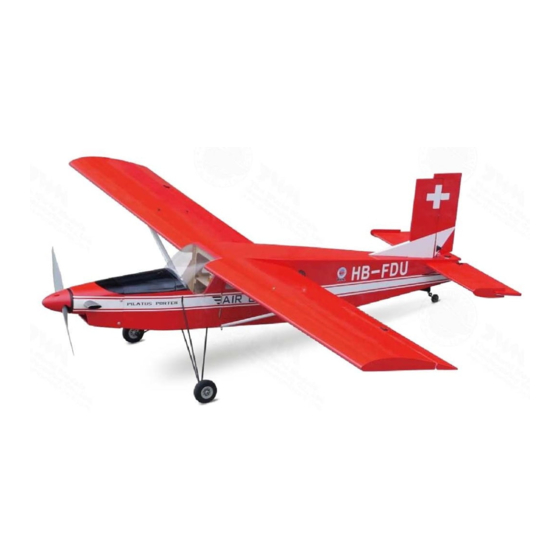
Requires:
Wing Span
Wing Area
Flying Weight
Fuselage Length
Warning! This model is not a toy.
It is designed for maximum performance. Please seek advice if one is not familiar with this kind
of engine powered precision model. Operating this model without prior preparation may cause
injuries. Remember, safety is the most important thing. Always keep this instruction manual at
hand for quick reference.
The World Models
Manufacturing Co., Ltd.
www.theworldmodels.com
A340PO32201904
"Glow Power" requires 4-channel radio w/5 standard
servos, 2-stroke 0.40-0.46 engine, or "Electric Power"
requires 4-channel radio w/ 4 standard servos,
Outrunner Motor KM37490750 w/Radial Mount
Adaptor HW2340300, 40A Brushless ESC, 4 cells
14.8V 3200mAh Lipo battery and charger
*Specifications are subject to change without notice.*
Specifications
64 in / 1625 mm
592 sq in / 38.2 sq dm
5.5 Ib / 2500 g
45.5 in / 1155 mm
INSTRUCTION MANUAL
FACTORY PRE-FABRICATED
ALMOST-READY-TO-FLY(ARF)SERIES
MADE IN CHINA
( A340 )
Advertisement

Related Manuals for THE WORLD MODELS A340


Summary of Contents for THE WORLD MODELS A340
- Page 1 INSTRUCTION MANUAL ( A340 ) Requires: "Glow Power" requires 4-channel radio w/5 standard servos, 2-stroke 0.40-0.46 engine, or "Electric Power" requires 4-channel radio w/ 4 standard servos, Outrunner Motor KM37490750 w/Radial Mount Adaptor HW2340300, 40A Brushless ESC, 4 cells 14.8V 3200mAh Lipo battery and charger...
- Page 2 INDEX BEFORE YOU BEGIN PARTS LIST ASSEMBLY P.3-P.13 SAFETY PRECAUTIONS P.14 BEFORE YOU BEGIN Read through the manual before you begin, so you will have an overall idea of what to do. Check all parts. If you find any defective or missing parts contact your local dealer. Please DRY FIT and check for defects for all parts that will require CA or Epoxy for final assembly.
- Page 3 Parts List 1. DECALS: A340 DEC -- set 10. SIDE WINDOWS -- 1 set MAIN WING -- 1 pair WIND SHIELD -- 1 pc. FUSELAGE -- 1 pc. SCREW PWA2.3x8mm -- 4 pcs SILICON GROMMETS PL1265035 d1.5xD6.5mm -- 4 pcs 2.
- Page 4 Decals Cut out decal sheet, peel off backing sheet and apply on fuselage and wings. Decal Main wings Bottom View Fuselage Left View Right View Instrument Panel Top View A340PO32201904...
- Page 5 Stabilizer & Elevator PM3x20mm Screw d3.2xD7mm Washer Pre-glued PM3x20mm Washer d3.2xD7mm The hinges are factory glued. Vertical Fin & Rudder Pre-glued B=B' Right View The hinges are factory glued. Remove coverings for all surfaces in contact before applying A/B epoxy glue. Rudder Pushrod PB2x14mm Screw...
- Page 6 Elevator Pushrod PB2x14mm Screw PB2x14mm Fuel Tube D6x5mm Tri-horn M3 x 14mm Pushrod Ø1.8x590mm Clevis Ø1mm pilot holes for World Models horn are pre-drilled. Please look for pin-hole marks at under side of control surfaces. Tail Landing Gear PA3x12mm Screw PM2x12mm Screw PA3x12mm...
- Page 7 This step is for electric powered. Please follow step 8B if your model is engine powered. Electric PWA2.6x12mm Screw M3x8mm PA3x10mm Screw d3xD7mm M3x12mm d1.5xD6.5mm Silicon Grommet Screw Propeller Adaptor HW2340300 Motor KP0011310 M2.5x11mm EZ Connector Solder Solder Brushless ESC Battery Tie Battery Optional Electric Power...
- Page 8 If Pilatus PC-6 Porter 40 is engine powered. Please follow this step. Engine Engine Mount PL5111030 PWA2.6x12mm Screw d3xD7mm PA3x10mm Screw M3x20mm d1.5xD6.5mm Silicon Grommet Screw M3x25mm d3xD7mm M3 Nut Linkage Connector Plastic Tube Plywood 5x50x72.5mm Throttle Pushrod d2xD3x270mm Throttle Servo Ø1.2x330mm Optional Glow Engine Power Package...
- Page 9 Servos Setting Fuel Tube D6x5mm Rudder Pushrod Straper Rudder Servo Ø1.8x450mm J1(Pushrod Ø1.8x85mm) Elevator Servo Elevator Pushrod Elevator Servo Ø1.8x410mm Pushrod Connector Install and arrange the servo as shown in the diagram. Windows PWA2.6x12mm Screw d1.5xD6.5mm Silicon Grommet Screw PWA2.6x12mm d1.5xD6.5mm Securely glue the windows to the fuselage.
- Page 10 Aileron Servo PWA2x8mm n Screw PWA2x8mm 1.5mm Servo wire 1.5mm Pre-glued Bottom View The hinges are factory glued. Aileron Pushrod PB2x20mm Screw PB2x18mm Screw Fuel Tube Straper D6x5mm Pushrod PB2x20mm Ø1.8x86mm PB2x18mm Fuel Tube Tri-horn M3 x 14mm D6x5mm Clevis Ø1mm pilot holes for World Models horn are pre-drilled.
- Page 11 Main Wing PA3x20mm Screw PA3x20mm d3.2xD12mm d3.2xD12mm Washer Insert carbon wing tubes into right wing, apply the PA Screws. PA3x20mm d3.2xD12mm Insert the right wing tubes through the Fuselage, and then install the left wing. Press the wings against the fuselage then apply PA screws to the left wing. Wing Struts M3x12mm Socket Head Screw PA3x12mm...
- Page 12 This step is for electric powered. Please follow step 16B if your model is engine powered. Radio 180mm Y-Cord Aileron Servo (L) Elevator Servo Aileron Servo (R) Rudder Servo Receiver Plug in the Aileron Servos wire to channel 1 Plug in the Elevator Servo wire to channel 2 Plug in the ESC Throttle wire to channel 3 Plug in the Rudder Servo wire to channel 4 Battery Mat...
- Page 13 Battery Cover Wing Setting A=A` B=B` C=C` P.12 A340PO32201904...
- Page 14 Control Throws Adjust the control throws as shown in the diagram. These throws are good for general flying. You can adjust according to your personal preference. Elevator 25mm 25mm Rudder 40mm 40mm Ailerons 30mm 30mm C.G. The ideal C.G. for electric powered model is 63mm ( 2.5 in. ) behind the leading edge measured at where the wing meets the fuselage.
- Page 15 Warning! Important Safety Precautions # First time flyer should never fly by himself / herself. Assistance from experienced flyer is absolutely necessary. # Pre-flight adjustment must be done before flying, it is very dangerous to fly a badly pre-adjusted aircraft. KM37490750 Outrunner Motor is specially designed to be powered by 2-stroke 0.40-0.46 engine, using a more powerful engine does not mean better performance.
- Page 16 LINKAGE CONNECTOR HW7111050 & HW7111060 Drill 2mm hole at servo horn. Insert linkage connector into servo horn. Make sure shoulder of screw is cleared from servo horn. Add washer to reduce play if necessary. Shoulder Tighten up the round nut against the shoulder.
- Page 17 Usage of the transparent 3D template This transparent 3D template is used for position guidance of the actual cutting of the pre-painted cowling. Simply cut the transparent 3D template to fit your engine and exhaust pipe, then slide onto the actual cowling and use as template to mark the openings required for final cutting.
- Page 18 Pl8210010 Large Clevis • Small Clevis • Radial Mount Adaptor Set Outrunner Motor 37 / 49 -750kv Electronic Speed Control 15A KM37490750 Code No. Size KC2015A01 37 x 19 x 7mm 1 pc -Kv (rpm / V): 750 -Current : 15A continuous -Operating Power: 590 W -Weight : 22g (with wires) -Operating Voltage: 8.5 - 18V...
- Page 19 Optional Parts ACCESSORIES) Clevis Wrench 180mm Extension Code No. Size Package Code No. Size Package PL8210010 1 set KW0011800 180mm 1 set Large Clevis Small Clevis Special tool for clevis installation. Suitable for standard and small (EP) clevis. 180mm Y-Cord Code No.
- Page 20 A340PO32201904...
Need help?
Do you have a question about the A340 and is the answer not in the manual?
Questions and answers