Advertisement
Quick Links
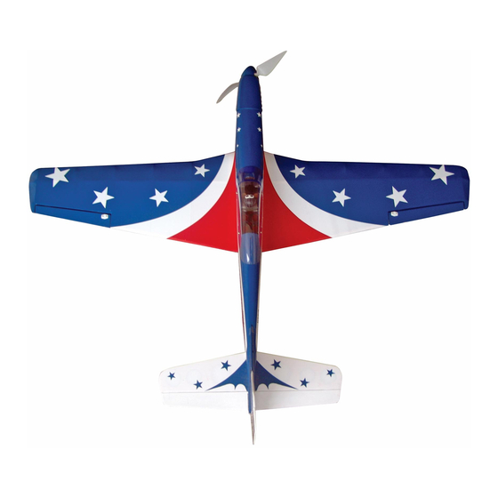
P-51 MUSTANG 46
0.46 cu. in. displacement 2-stroke
Requires: 5-channel radio w/ 5 standard servos
and 1 low profile retract servo
Wing Span
Wing Area
Flying Weight
Fuselage Length
Warning !This model is not a toy.
It is designed for maximum performance. Please seek advice if one is not familiar with this kind
of engine powered precision model. Operating this model without prior preparation may cause
injuries. Remember, safety is the most important thing. Always keep this instruction manual at
hand for quick reference.
A055PO17000906
Specifications
* Specifications are subject to change without notice.*
INSTRUCTION MANUAL
57.5 in / 1460 mm
585 sq in / 37.4 sq dm
6 lbs / 2.7 kg
49.6 in / 1260 mm
FACTORY PRE-FABRICATED
ALMOST-READY-TO-FLY (ARF) SERIES
)
(
A055
MADE IN CHINA
Advertisement

Related Manuals for THE WORLD MODELS A055


Summary of Contents for THE WORLD MODELS A055
- Page 1 INSTRUCTION MANUAL P-51 MUSTANG 46 A055 0.46 cu. in. displacement 2-stroke Requires: 5-channel radio w/ 5 standard servos and 1 low profile retract servo Specifications Wing Span 57.5 in / 1460 mm Wing Area 585 sq in / 37.4 sq dm Flying Weight 6 lbs / 2.7 kg...
- Page 2 P-51 MUSTANG 46 I N D E X BEFORE YOU BEGIN P. 1 PARTS LIST P. 2 ASSEMBLY P. 3 -11 SAFETY PRECAUTIONS P.11 BEFORE YOU BEGIN Read through the manual before you begin, so you will have an overall idea of what to do. Check all parts.
- Page 3 Parts List 1. MAIN WING -- 1 pair 14. COWLING -- 1 pc. TRANSPARENT 3D TEMPLATE -- 1 pc. 3. RETRACTABLE LANDING GEAR -- 1 pair SCREW PWA2.6x12mm -- 4 pcs MAIN LANDING GEAR COVER -- 1 set SILICON GROMMET d1.5xD6.5mm -- 4 pcs 4.
- Page 4 Aileron Aileron Servo Lead Pre-glued Bottom View Landing Gear KA 3x14mm KA 3x14mm Screw 1.5mm Factroy Installed Landing Gear 3mm Set Screw 3mm Set Screw 4.1mm Wheel Collar A055PO17000906...
- Page 5 Main Wing Please dry fit wing joiner into left and right wing to make sure they fit with the proper dihedral angle, mark the wing joiner if necessary. Apply epoxy glue to both sides of all surfaces in contact. Use a stick to apply the glue to inner side of wing joiner sleeve, and apply the glue to wing joiner before putting them together.
- Page 6 Aileron Linkage PM 2x20mm PM 2x16mm PM 2x16mm Screw Fuel Tube Ø6x5mm PM 2x20mm Screw Straper 1mm pilot holes for World Tri-horn(S) 2m m Fuel Tube 3x14mm Models tri-horn are pre-drilled. look for pin-hole marks Please at under sideof control surfaces. Stabilizer &...
- Page 7 Tail Landing Gear PA 3x12mm Screw PM 2x12mm Screw 2mm Nut 2. 1mm Collar 2m m 3mm set screw 1.5mm 1.5mm PM 2x12mm M2mm NUT PA 3x12mm 2.1mm Collar Fuel Tank Fuel Tank 320cc Install Balsa 10x10x98.5mm (For Fuel Tank Position Fixing) Fuel Tank Bottom View Engine Mount...
- Page 8 Engine PM 3.5 x30mm PM 3.5x30mm Screw Washer d3.5xD8mm 3.5mm Washer 3.5mm Nut IIIustration is for upright mounting of engine. Side or inverted mounting is possible by rotating the engine Install Engine position mount. Thrust angle Spinner will not be affected. Ø82mm Washer d3.5xD8mm...
- Page 9 Radio Equipment Rudder Pushrod Elevator Pushrod Balsa 6x6x140mm Straper Fuel Tube Ø6x5mm Plywood 3x95x163mm Throttle Pushwire Ø1.2x460mm Plastic Tubed2xD3x300mm Bottom View Radio Equipment Install and arrange the servo as shown in the diagram. Elevator Pushrod J1(Pushrod Ø1.8x93) Ø1.8x93mm Elevator Servo M2 Nut J2(Pushrod Ø1.8x518) Pushrod...
- Page 10 Linkage Rudder Tri-horn Fuel Tube PM 2x12mm Screw 2m m PM 2x16mm Screw Tri-horn (L) PM 2x12mm 3x14mm PM 2x16mm Elevator Tri-horn 1mm pilot holes for World Models Fuel Tube tri-horn are pre-drilled. Please look for pin-hole marks at under side of control 2m m surfaces.
- Page 11 Main Wing PM 3x13mm d3xD7mm Washer PM 3x13 mm Screw d3xD7mm Washer Wing Setting Adjust the wing and fuselage configuration as shown in the diagrams. Control Throws Adjust the control throws as shown in the diagram. Throws are good for general Elevator flying.
- Page 12 The ideal C.G. position is 128mm (5.04in)behind C.G. the leading edge measured at where the wing meets the fuselage. In order to obtain the C.G. specified, add weight to the fuselage or move the battery position. Check the C.G. before flying.
- Page 13 LINKAGE CONNECTOR HW7111050 & HW7111060 Drill 2mm hole at servo horn. Insert linkage connector into servo horn. Make sure shoulder of screw is cleared from servo horn. Add washer to reduce play if necessary. Shoulder Tighten up the round nut against the shoulder.
- Page 14 Usage of the transparent 3D template This transparent 3D template is used for position guidance of the actual cutting of the pre-painted cowling. Simply cut the transparent 3D template to fit your engine and exhaust pipe, then slide onto the actual cowling and use as template to mark the openings required for final cutting.
- Page 15 A055PO17000906...
- Page 16 A055PO17000906 A055PO17000906...
Need help?
Do you have a question about the A055 and is the answer not in the manual?
Questions and answers