Table of Contents
Advertisement
Quick Links
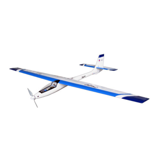
Radio required : 3 channels, 4 servos airplane radio
Wing Span
Wing Area
Flying Weight
Fuselage Length
Warning !This model is not a toy.
It is designed for maximum performance. Please seek advice if one is not familiar with this kind
of engine powered precision model. Operating this model without prior preparation may cause
injuries. Remember, safety is the most important thing. Always keep this instruction manual at
hand for quick reference.
Aure
Specifications
* Specifications are subject to change without notice.*
INSTRUCTION MANUAL
81.5 in / 2070mm
572.0 sq in / 36.9 sq dm
3.3 lbs / 1500g
43.5 in / 1100mm
FACTORY PRE-FABRICATED
ALMOST-READY-TO-FLY (ARF) SERIES
MADE IN CHINA
Advertisement
Table of Contents

Related Manuals for THE WORLD MODELS Aure


Summary of Contents for THE WORLD MODELS Aure
- Page 1 INSTRUCTION MANUAL Aure Radio required : 3 channels, 4 servos airplane radio Specifications 81.5 in / 2070mm Wing Span Wing Area 572.0 sq in / 36.9 sq dm Flying Weight 3.3 lbs / 1500g Fuselage Length 43.5 in / 1100mm * Specifications are subject to change without notice.*...
-
Page 2: Before You Begin
Aure I N D E X BEFORE YOU BEGIN P. 1 PARTS LIST P. 2 ASSEMBLY P. 3 - 11 SAFETY PRECAUTIONS P. 11 BEFORE YOU BEGIN Read through the manual before you begin, so you will have an overall idea of what to do. -
Page 3: Parts List
Parts List 1. FUSELAGE -- 1pc. 9. PLASTIC PARTS :-- CLEVIS --3 pcs 2. MAIN WING -- 1 pair STRAPER --3 pcs HORN --3 sets 3. ELEVATOR --1 pc. PLASTIC PLATE 1.5x33.5x71mm --1 pc. 4. RUDDER --1 pc. 10.METAL PARTS :-- LINKAGE CONNECTOR --1 set 5. -
Page 4: Aileron Servo
Aileron Aileron Servo Wooden 8x16x24mm 2.5mm Screw PWA2 x 8mm Screw PM2 x 30mm Bottom View PWA2x8mm Straper PM2x12mm Fuel Clevis Tube Fuel Tube Ø6x5mm Metal Rod Horn Ø1.8x50mm... -
Page 5: Rudder Pushrod
Rudder Rudder Pushrod Screw PM2 x 20mm Rudder Pushrod Ø6x5mm Fuel Tube Ø6x5mm Clevis PM2 x 20mm... - Page 6 Stabilizer / Elevator Stabilizer Joiner Ø3x127mm Stabilizer Joiner Ø3x144mm Top View...
- Page 7 Stabilizer / Elevator Bottom View Servo Set LINKAGE CONNECTOR Set Screw 3 X 3mm Included with the Radio Set. Rudder Pushrod. L i n k a g e C o n n e c t o r Washer Rudder Servo. Please refer to attached sheet for linkage connector installation.
- Page 8 Main Wing Bottom View Lead to Aileron Servo Washer d3 x D12mm Screw PM3 x 16mm Wing Joiner Ø6x211mm Wing Joiner Ø6x142mm Top View PM3x16mm d3xD12mm...
- Page 9 Canopy Wing Setting Adjust the wing and fuselage configuration as in the diagrams. A = A' B = B' C = C'...
-
Page 10: Control Throws
Control Throws Adjust the control throws as shown in the diagram. These throws are good for general flying. You can adjust according to your Elevator personal preference. 40mm 40mm Rudder 53mm 53mm Aileron 15mm 15mm C.G. The ideal C.G. position is 75mm (2.9 in.) behind the leading edge measured at where the wing meets the fuselage. - Page 11 ADDENDUM LINKAGE CONNECTOR HW7111030 & HW7111060 Drill 2mm hole at servo horn. Insert linkage connector into servo horn. Make sure shoulder of screw is cleared from servo horn. Add washer to reduce play if necessary. Shoulder Tighten up the round nut against the shoulder.
- Page 12 The World Models Manufacturing Co., LTD. www .thew orldm odels .com G1040405...
Need help?
Do you have a question about the Aure and is the answer not in the manual?
Questions and answers