
Related Manuals for Mackworth SA180E


Summary of Contents for Mackworth SA180E
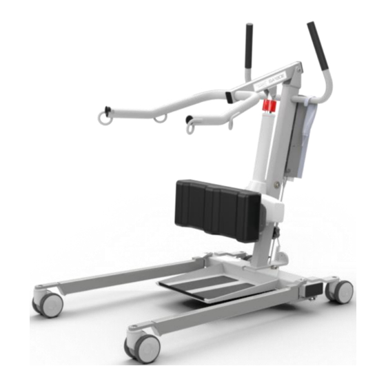
- Page 1 SA180E Stand Aid Service Manual Doc. No. 995064 Revision of document: A Rev Date: 26.04.2021...
-
Page 2: Table Of Contents
Contents 1.0 – Introduction ..............................3 2.0 – Safety Precautions ............................3 3.0 – Servicing ................................. 4 4.0 – Test Procedure ............................... 6 5.0 – Tools, Equipment and Lubricants Required for Servicing ................7 6.0 – Decommissioning ............................8 7.0 – Spare Parts List............................... 9 8.0 –... -
Page 3: Introduction
This Manual will explain how to carry out interim servicing and parts replacement on the Mackworth Essentials SA180E Stand Aid safely and effectively. This document is divided into sections to help a Service Engineer find the correct information. Each section will show in a step by step fashion the correct way to disassemble and assemble the Stand Aid. -
Page 4: Servicing
3.0 – Servicing To be completed by Approved Service Engineer Maintenance should be completed by an approved service engineer every 6 months to ensure the products required standard is maintained. The service history of the product should be documented each service. When Servicing the Stand Aid, ensure to fill out the Service Log which is located in the back of the User Manual. - Page 5 Verify all Handset functions are in working order. Ensure LED’s are working correctly. Knee Pad: Inspect the Knee Pad for damage including cuts and breaks. Inspect the Knee Pad is functioning as intended, the Knee Pad should hold its current position and not lower due to gravity. Ensure the Knee Pad Height and Length adjustment functions correctly.
-
Page 6: Test Procedure
4.0 – Test Procedure Below is the full testing procedure required to complete an Annual Stand Aid Service. The SWL (180Kg) is an essential load for the testing of the Stand Aid and a mode of transportation to transport the weights to the hoist is required. 1. -
Page 7: Tools, Equipment And Lubricants Required For Servicing
5.0 – Tools, Equipment and Lubricants Required for Servicing When carrying out work on the Mackworth Essentials SA180E Stand Aid you will require the following: Tools Required 3mm Allen Key 4mm Allen Key x2 5mm Allen Key x2 6mm Allen Key x2... -
Page 8: Decommissioning
6.0 – Decommissioning When the Stand Aid has completed its life cycle and can no longer perform to its intended use safely the Stand Aid must be decommissioned by an approved Service Engineer. The following specifies the importance of correct disposal procedure including local laws and being environmentally friendly. Please observe the local laws on recycling and respect the current laws for disposal within the community the device is being used within. -
Page 9: Spare Parts List
Battery Pack (2.9 Ah Lead Acid) 510091 Mains Snap Lead 510092 Charger Lead (UK Plug) 520034 Lift Actuator Lead (700mm) 999064 Mackworth Essentials SA180E User Manual 992064 Mackworth Essentials SA180E Spare Parts Manual 995064 – Revision A Page 9 of 36... -
Page 10: Troubleshooting
Servicing. If the fault is not found and/or the solutions do not correct the problem, contact your local Mackworth authorized dealer immediately – contact details are provided on the last page of this manual. 8.1 – Stand Aid doesn’t turn on Operate the handset to determine if the Stand Aid powers up. -
Page 11: Stand Aid Doesn't Charge
8.2 – Stand Aid doesn’t charge Connect the Stand Aid charging lead from the Hoist to the Wall Socket. (Ensuring that the lead is connected properly) to determine if the Stand Aid charges. If the control box LED does not illuminate a steady orange, follow the Troubleshooting Guide below. -
Page 12: Stand Aid Doesn't Lift Load Correctly - Stop/Start Action
Action Guide 1. Remove the Stand Aid from charge. 2. Connect the Lift Actuator Cable correctly. See section 9.2.2 for guidance. 3. Replace the Cable. See Section 9.2.2 for guidance. 4. Replace the Lift Actuator. See Section 9.5 for guidance. 5. -
Page 13: Stand Aid Has Power But Does Not Respond To Handset Commands
8.7 – Stand Aid has Power but does not respond to Handset commands Attempt to raise/lower the Actuator and Open/Close the Legs with the handset but the Stand Aid does not respond. There is Power as the LED indicates when it charges. Troubleshooting Guide 1. -
Page 14: Servicing - Removal And Replacement
Stand Aid. The step by step process is to be followed in sequence to perform a successful service on the Stand Aid. Unless stated otherwise, all images refer to a Mackworth Essentials SA180E. NOTE: Before carrying out any work on a Mackworth Essentials SA180E Stand Aid, remember to remove the charger lead and remove any external power source. -
Page 15: Cables
Refitting / Replacement Step 3 – Refitting is a reversal of the removal process noting the following points: A) Reposition the Battery above the Control Box – Push the Battery inward and the Battery will “click” into place. 9.2 – Cables In this section it will explain the correct procedure on removing/ refitting the Cables for servicing procedures or replacement. -
Page 16: Cable - Lift Actuator
9.2.2 – Cable – Lift Actuator Removal Step 1 – Remove the Jack End of the Cable which ports the Control Box by pulling downward. (This is the middle Control Box Port as shown in the image) Step 2 – Release the cable from the Actuator by turning the lock manually as shown. Step 3 –... -
Page 17: Cable - Charger
Step 4 - Remove the cable from any clips that are routing it along the Mast. Refitting / Replacement Step 5 - Refitting is a reversal of the removal process noting the following points: A) When fitting the Cable into the Actuator port, ensure the locator aligns with the locator inside the actuator port. -
Page 18: Control Box
Step 4 – If the Plug has not already been removed from the wall socket, remove the plug from its fixing to the Mast. Refitting / Replacement Step 5 - Refitting is a reversal of the removal process noting the following points: A) Ensure that the snap lead is refitted in the correct orientation in the Control Box port, and that the snap lead is securely fastened to its latch and will not easily displace. -
Page 19: Attachment Bracket
9.4 – Attachment Bracket In this section it will explain the correct procedure on removing and reinstalling the Attachment Bracket for servicing procedures or replacement. Removal Step 1 – Remove the Battery (refer to section 9.1) Step 2 – Remove the Cables/Leads from the Control Box (refer to section 9.2) Step 3 –... -
Page 20: Lift Actuator
9.5 – Lift Actuator In this section it will explain the correct procedure on removing and reinstalling the Lift Actuator for servicing procedures or replacement. Removal Step 1 – Remove the Lift Actuator Cable. (See section 9.2.2) Step 2 – Using two 4mm Allen Keys, remove one of the screws and washer from the pin at the Top Actuator fixing point. - Page 21 Step 5 – Pull the Pin out from the bottom fixing to release the Actuator. Step 6 – Remove the Actuator and rest the Upper Assembly on the Stand Aid. Refitting / Replacement Step 7 - Refitting is a reversal of the removal process noting the following point: A) Ensure the Actuator is fitted in the correct orientation.
-
Page 22: Upper Assembly
9.6 – Upper Assembly Within this section it will explain the correct procedure on removing and reinstalling the Upper Assembly for servicing procedures or replacement. Removal Step 1 – Remove the Lift Actuator Cable. (See section 9.2.2) Step 2 – Remove the Lift Actuator. (See section 9.5) Step 3 –... - Page 23 Step 6 – The Upper Assembly can now be removed. Refitting / Replacement Step 7 - Refitting is a reversal of the removal process noting the following point: A) Ensure the threaded boss is placed within the Upper Assembly when fitting. B) Ensure Loctite 243 is applied to both bolts when fixing the Upper Assembly.
-
Page 24: Leg Rod Assembly
9.7 – Leg Rod Assembly Within this section it will explain the correct procedure on removing and reinstalling the Manual Leg Rods for servicing procedures or replacement. Removal Step 1 – Remove the Foot Tray from the Base. (Refer to section 9.12) Step 2 - Place the Stand Aid on its side for easier service. -
Page 25: Leg Actuator Assembly
9.8 – Manual Leg Opener Within this section it will explain the correct procedure on removing and reinstalling the Manual Leg Rods for servicing procedures or replacement. Removal Step 1 – Remove the Foot Tray from the Base. (Refer to section 9.12) Step 2 - Place the Stand Aid on its side for easier service. - Page 26 Step 8– Remove the Bolt securing the Leg Pivot Plate to the Base using an 8mm Allen Key. Ensure to grab the spacer, black washer and white washer. Step 9 – Remove the Leg Leaver Plate as shown, ensure to grab the white washer beneath, seen in the image.
-
Page 27: Front Castor
Refitting / Replacement Step 10 - Refitting is a reversal of the removal process noting the following points. A) Ensure all parts are placed in the correct order when attaching the Leg Pivot Plate, this includes: Bolt, Spacer, Black Washer, White Washer, Leg Pivot Plate, and White Washer. -
Page 28: Rear Castor
9.10 – Rear Castor Within this section it will explain the correct procedure on removing and reinstalling the Rear Castor for servicing procedures or replacement. Removal Step 1 – Remove the Foot Tray from the Base. (Refer to section 9.12) Step 2 - Place the Stand Aid in its side for easier service –... -
Page 29: Leg - (Lh Leg And Rh Leg)
9.11 – Leg – (LH Leg and RH Leg) Within this section it will explain the correct procedure on removing and reinstalling the legs of the hoist, images refer to one leg only but same applies to both. Removal Step 1 – Remove the Foot Tray from the Base. (Refer to section 9.12) Step 2 - Place the Stand Aid in its side for easier service –... -
Page 30: Foot Tray
9.12 – Foot Tray Within this section it will explain the correct procedure on removing and reinstalling the Foot Tray for servicing procedures or replacement. Removal Step 1 – Foot Tray is attached to the Base by the Pins circled in the image below. (Where applicable, use circlip pliers to remove the retaining circlips) Step 2 –... -
Page 31: Knee Pad
9.13 – Knee Pad Within this section it will explain the correct procedure on removing and reinstalling the Knee Pad for servicing procedures or replacement. Removal Step 1 – Using two 17mm Spanners, remove a nut from either side of the Knee Pad Attachment Bar. - Page 32 Step 4 – Pull the Index Plunger outward to fully remove the Inner Knee Pad Pivot Assembly. Step 5 – Use a 6mm Allen Key to remove the bolt securing the Outer Knee Pad Pivot Assembly. Grab the Spacer while removing the Bolt. Step 6 –...
- Page 33 D) When reattaching the Knee Pad to the Threaded Bar, ensure the Washers are fitted in the correct positions. Nut, washer, nylon washer, Knee Pad, nylon washer, Inner Knee Pad Pivot Assembly, nylon washer, Knee Pad, nylon washer, washer, nut. 995064 –...
-
Page 34: Base
9.14 – Base Within this section it will explain the correct procedure on removing and reinstalling the Base for servicing procedures or replacement. Removal Step 1 – Remove the Leg Actuator Cable. (See section 9.2.3) Step 2 - To detach the Mast and Upper Assembly from the Base the Two Star Knobs shown must be removed. -
Page 35: Mast
9.15 – Mast Within this section it will explain the correct procedure on removing and reinstalling the Mast for servicing procedures or replacement. Removal Step 1 – Remove the Battery from the Stand Aid. (See section 9.1) Step 2 – Remove all Cables from the Control Box. (See section 9.2) Step 3 –... - Page 36 While every effort has been made to ensure the accuracy of information contained in this assembly and installation manual, no liability can be accepted by Mackworth for any errors or omissions. Mackworth operates a policy of continuous improvement. Specifications and other data are subject to change without notice.
Need help?
Do you have a question about the SA180E and is the answer not in the manual?
Questions and answers