Advertisement
Quick Links
Instruction Manual
Thank you for purchasing this TAKEX passive infrared sensor.
This sensor will provide long and dependable service when properly installed.
Please read this Instruction Manual carefully for correct and effective use.
Please note : This sensor is designed to detect passing objects and to initiate a signal ; it is not a burglary-preventing device.
TAKEX is not responsible for damage or losses caused by accident, theft, Acts of God (including lightning),
abuse, misuse, abnormal usage, faulty installation or improper maintenance.
1
PARTS DESCRIPTION
Mounting Base
Grip Bolt
Mounting Base
Accessories
Tapping screw
Tapping screw
φ6×30 (4 pcs.)
φ4×8 (1 pc.)
Combining band
(1 pc.)
2
WIRING
Power
Red
10.5V-30V DC
Black
(non-polarity)
3
INSTALLATION
DO'S AND DON'T'S
・Install the sensor in such a direction that people are
more likely to cross the detection zones.
・Do not install in a site which is directly by an air
conditioning exhaust vent.
・Avoid direct sun light shining on the window of the
sensor.
・Do not install in a site which is subject to electrical
noise.
・Install sensor with its sensitivity volume downward.
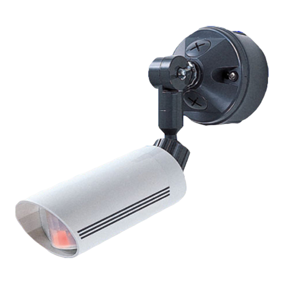
PASSIVE INFRARED SENSOR
PA-15WE ( Wide angle, 15m )
PA- 30NE ( Long range, 30m )
Mounting Box
Ball Lock
Sensitivity
Volume
(Set at factory)
Operation LED
Instruction manual
Dry contact
Blue
relay output
N ・ C
Yellow
N ・ O
1c
White
30V, 0.5A
COM.
HOW TO INSTALL
(4)
Plug unused screw holes on
Mounting Base with push rivets
provided.
(5)
Refer to 4. ANGLE ADJUSTMENT
and adjust the angle of the sensor.
NOTE :
Wire through the lower wire lead access on
Mounting Box to prevent water leakage.
4
ANGLE ADJUSTMENT
180°
variable
・Loosen the Grip bolt and ball lock
Loosen
Tighten
・Do not fail to set Sensor Unit to a
The direction of rotation of the left and right grip bolts is the same.
Please do not rotate each in the opposite direction.
Please refer to the direction of rotation described on the body
sticker.
(1)
Install Mounting Box.
Break knockouts
Mounting
(mounting holes) from
Hole
inside with a screw
driver, etc.
Hole for
Tighten screws
Vinyl Tie
provided.
(2)
Refer to 2. WIRING
and connect wires.
Tie up wires inside the
box with a vinyl tie
provided.
(3)
Attach Sensor Unit to
Mounting box with
screws provided.
You can install the
sensor to standard
single gang electrical
box (pitch : 83.5 or
66.7mm) available in
the market.
Grip bolt
180°
movable
180°
movable
Ball lock
90°
movable
before adjusting to the required
angle.
After angle adjustment, tighten
them.
lower angle than horizontal.
Advertisement

Related Manuals for Takex PA-15WE


Summary of Contents for Takex PA-15WE
- Page 1 Please note : This sensor is designed to detect passing objects and to initiate a signal ; it is not a burglary-preventing device. TAKEX is not responsible for damage or losses caused by accident, theft, Acts of God (including lightning), abuse, misuse, abnormal usage, faulty installation or improper maintenance.
- Page 2 Limited Warranty : 10.5V DC to 30V DC (non polarity) Supply voltage TAKEX products are warranted to be free from defects in material and workmanship for 12 months from original date of shipment. Our warranty does not 25mA or less...