Advertisement
Quick Links
Thank you for purchasing this product. Before using the products, please read this instruction manual carefully to ensure correct operation.
1
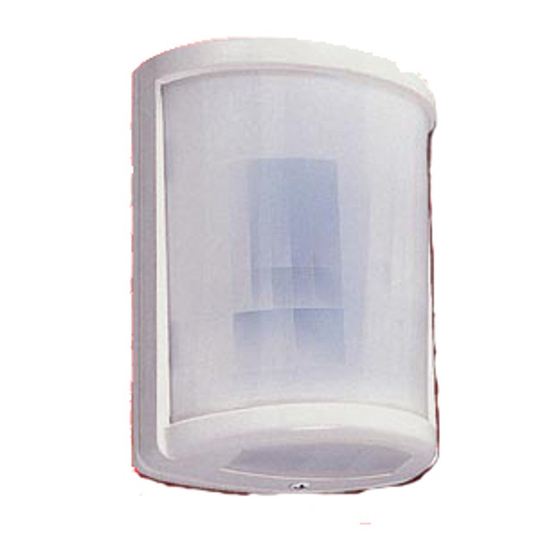
PRODUCT DESCRIPTION
BASE
COVER LOCKING
SCREW
2
PRECAUTIONS
This indicates the possibility of severe injury, and
Warning
even death, if ignored or a user handles the unit
incorrectly.
We categorize these precautions throughout the manual using the following symbols.
A prohibited action, you must not do.
Do not disassemble or modify this device. This may cause a fire,
electrical shock, or malfunction of the device.
If the following events occur, turn off the power of the unit
immediately, and ask the place of purchase for repair. Failure to
follow this may result in fire, electric shock, and/or malfunction.
• Smoke, abnormal odor, and/or sound are found
• Liquid, such as water, and/or foreign material has entered the unit
• The unit has deformed and/or damaged parts
Do not install this device in a location that cannot support its weight.
This may lead the device to fall and cause an injury or malfunction
of the device.
Do not apply impact to the unit.
Strong impact may result in performance deterioration and/or
damage to the unit.
The unit may not operate properly near devices that generate a
strong electric or magnetic field.
Also, devices near the unit may not operate properly due to the
magnetic field and/or magnetism generated from the unit.
Make sure to confirm before operation.
Make sure to perform a sufficient operation check on the whole
system before operation.
PASSIVE INFRARED SENSOR
Instruction Manual
COVER
CORNER MOUNTING HOLE
(4 CORNERS)
(KNOCKOUT)
WIRING CAHANNEL
REFLECTOR FOR
CREEP ZONE
ALARM LED
WALL MOUNTING
HOLE (KNOCKOUT)
LENS
WIRING HOLE
(KNOCKOUT)
This manual describes precautions by classifying them based on degrees of danger and
Be sure to observe
damage that would be generated if using the unit incorrectly.
PA-480S
MODE SELECTOR
This indicates the possibility of minor injury and/or
damage to properties, or of a notification delay in your
Caution
system due to false operations and/or non-detection, if
ignored or a user handles the unit incorrectly.
An action you must do, and information you should keep in mind.
Warning
Mount the unit on solid ceilings or wall surfaces where reinforcement
materials are used. If you mount the unit on non-wood materials such
as plaster board or concrete, securely mount it using anchors and
mounting screws that match the wall materials. Unstable mounting
may result in injury and/or property damage if the unit falls.
Do not use the unit with power voltage levels other than those
specified. Failure to follow this may result in fire, electric shock, and/or
malfunction.
Do not connect devices that exceed the indicated capacity to the
output contact of the unit. Failure to follow this may result in electric
shock, fire, and/or malfunction.
Do not touch terminals with wet hands. Failure to follow this may
result in electric shock.
Caution
Refer to the detection area chart, and select the installation location.
Then, check the actual operation, and adjust the appropriate area.
Make sure to check operation when you move tables and partitions
to change the layout in protected rooms.
Do not install the unit in places subject to oil, smoke, steam, high
humidity, and/or a lot of dust.
Electricity that is conducted through these substances may result in
fire, electric shock, and/or false operation.
WIRING HOLE (KNOCKOUT)
Accessories
WALL MOUNTING
HOLE
(KNOCKOUT)
Instruction
INNER UNIT
Manual
(5 POSITIONS
: 1 pc
ADJUSTMENT)
AREA LOCK HOLE
(TO BE SCREWED)
Area lock screw
φ3×10
: 1 pc
ALARM LED
TAMPER SWITCH
Tapping screw
φ4×30
: 2 pcs
Advertisement

Related Manuals for Takex PA-480S


Summary of Contents for Takex PA-480S
- Page 1 PASSIVE INFRARED SENSOR PA-480S Instruction Manual Thank you for purchasing this product. Before using the products, please read this instruction manual carefully to ensure correct operation. PRODUCT DESCRIPTION MODE SELECTOR WIRING HOLE (KNOCKOUT) COVER Accessories CORNER MOUNTING HOLE BASE (4 CORNERS)
- Page 2 Caution Avoid installing the unit in the following places. Ask qualified personnel for any electrical work necessary for Otherwise, non-detection and/or false detection may occur. installation, if required. • Places subject to strong direct or reflected light (sunlight, spotlight) Failure to follow this may result in fire and/or electric shock. •...
- Page 3 INSTALLATION Loosen the cover locking screw and remove Break knockouts of wiring holes required the cover. Do not remove the screw from the to connect wires. In case wiring through cover not to lose locking nut. upper wiring holes, pass the wires along wiring channels on either side of the base to connect them to the terminal.
- Page 4 TAKEX. All implied warranties with respect to TAKEX, including implied warranties for merchantability and implied warranties for fitness, are limited in duration to 12 months from original date of shipment. During the Warranty Period, TAKEX will repair or replace, at its sole option, free of charge, any defective parts returned prepaid.
Need help?
Do you have a question about the PA-480S and is the answer not in the manual?
Questions and answers